EP1527007B1 - Method and device for stacking sheet material - Google Patents
Method and device for stacking sheet material Download PDFInfo
- Publication number
- EP1527007B1 EP1527007B1 EP03766368A EP03766368A EP1527007B1 EP 1527007 B1 EP1527007 B1 EP 1527007B1 EP 03766368 A EP03766368 A EP 03766368A EP 03766368 A EP03766368 A EP 03766368A EP 1527007 B1 EP1527007 B1 EP 1527007B1
- Authority
- EP
- European Patent Office
- Prior art keywords
- stacker
- stripper
- sheet material
- stack
- stacker wheel
- Prior art date
- Legal status (The legal status is an assumption and is not a legal conclusion. Google has not performed a legal analysis and makes no representation as to the accuracy of the status listed.)
- Expired - Lifetime
Links
Images

Classifications
-
- B—PERFORMING OPERATIONS; TRANSPORTING
- B65—CONVEYING; PACKING; STORING; HANDLING THIN OR FILAMENTARY MATERIAL
- B65H—HANDLING THIN OR FILAMENTARY MATERIAL, e.g. SHEETS, WEBS, CABLES
- B65H29/00—Delivering or advancing articles from machines; Advancing articles to or into piles
- B65H29/38—Delivering or advancing articles from machines; Advancing articles to or into piles by movable piling or advancing arms, frames, plates, or like members with which the articles are maintained in face contact
- B65H29/40—Members rotated about an axis perpendicular to direction of article movement, e.g. star-wheels formed by S-shaped members
-
- B—PERFORMING OPERATIONS; TRANSPORTING
- B65—CONVEYING; PACKING; STORING; HANDLING THIN OR FILAMENTARY MATERIAL
- B65H—HANDLING THIN OR FILAMENTARY MATERIAL, e.g. SHEETS, WEBS, CABLES
- B65H31/00—Pile receivers
- B65H31/32—Auxiliary devices for receiving articles during removal of a completed pile
-
- B—PERFORMING OPERATIONS; TRANSPORTING
- B65—CONVEYING; PACKING; STORING; HANDLING THIN OR FILAMENTARY MATERIAL
- B65H—HANDLING THIN OR FILAMENTARY MATERIAL, e.g. SHEETS, WEBS, CABLES
- B65H2301/00—Handling processes for sheets or webs
- B65H2301/40—Type of handling process
- B65H2301/42—Piling, depiling, handling piles
- B65H2301/421—Forming a pile
- B65H2301/4212—Forming a pile of articles substantially horizontal
-
- B—PERFORMING OPERATIONS; TRANSPORTING
- B65—CONVEYING; PACKING; STORING; HANDLING THIN OR FILAMENTARY MATERIAL
- B65H—HANDLING THIN OR FILAMENTARY MATERIAL, e.g. SHEETS, WEBS, CABLES
- B65H2301/00—Handling processes for sheets or webs
- B65H2301/40—Type of handling process
- B65H2301/42—Piling, depiling, handling piles
- B65H2301/426—Forming batches
-
- B—PERFORMING OPERATIONS; TRANSPORTING
- B65—CONVEYING; PACKING; STORING; HANDLING THIN OR FILAMENTARY MATERIAL
- B65H—HANDLING THIN OR FILAMENTARY MATERIAL, e.g. SHEETS, WEBS, CABLES
- B65H2701/00—Handled material; Storage means
- B65H2701/10—Handled articles or webs
- B65H2701/19—Specific article or web
- B65H2701/1912—Banknotes, bills and cheques or the like
Abstract
Description
Die Erfindung betrifft ein Verfahren zum Stapeln von Blattgut sowie einen Spiralfachstapler, insbesondere zur Verwendung in einer Banknotenbearbeitungsvorrichtung.The invention relates to a method for stacking sheet material and to a spiral slot stacker, in particular for use in a bank note processing apparatus.
In herkömmlichen Banknotenbearbeitungsmaschinen werden die Banknoten im Allgemeinen in einem Stapel vereinzelt und mittels einer Transportstrecke an einer Sensoreinrichtung vorbeigeführt. Die einzelnen Banknoten werden von Sensoren der Sensoreinrichtung geprüft und abhängig vom Prüfergebnis bestimmten Zielorten bzw. Staplereinheiten zugeführt.In conventional banknote processing machines, the banknotes are generally singulated in a stack and guided past a sensor device by means of a transport path. The individual banknotes are checked by sensors of the sensor device and supplied to specific destinations or stacker units depending on the test result.
Zur Prüfung der Banknoten können mehrere Sensoren vorgesehen sein, die die Banknoten nach unterschiedlichen Kriterien beurteilen. Entsprechend sind mehrere Staplereinheiten vorhanden, die die Banknoten der unterschiedlichen Kategorien zu Einheiten einer einstellbaren Stückzahl stapeln. Sollen beispielsweise Banknoten einer bestimmten Kategorie mit einer Stückzahl von 100 Banknoten gestapelt werden, ist es notwendig, nach dem Eintreffen der einhundertsten Banknote am Stapler im kontinuierlichen Banknotenstrom eine Trennung zwischen der einhundertsten und der für den selben Stapler bestimmten nachfolgenden Banknote vorzunehmen.For checking the banknotes, a plurality of sensors may be provided which judge the banknotes according to different criteria. Correspondingly, there are a plurality of stacker units which stack the banknotes of the different categories into units of an adjustable number of units. For example, if banknotes of a certain category are stacked with a quantity of 100 banknotes, it is necessary to make a separation between the one hundredth and the subsequent banknote intended for the same stacker after the arrival of the one hundredth banknote on the stacker in the continuous banknote stream.
In diesem Zusammenhang ist es aus der
Aus der
Diese Lösung hat den Nachteil, dass bei höheren Transportgeschwindigkeiten relativ hohe Stellkräfte zur Beschleunigung des Trennelements aufgebracht werden müssen, was nur mit einem entsprechend hohen Aufwand erreicht werden kann. Bei der hohen Transportgeschwindigkeit kann eine sichere Funktion des Staplers nicht gewährleistet werden.This solution has the disadvantage that at higher transport speeds relatively high actuating forces must be applied to accelerate the separator, which can only be achieved with a correspondingly high cost. At the high transport speed, a safe operation of the truck can not be guaranteed.
In der
Im Zusammenhang mit der Lösung, bei der die bereits vereinzelten Banknoten im Stapler selbst zwischengespeichert werden, ist der Stapler als Spiralfachstapler ausgeführt, wie beispielsweise in der
Als nachteilhaft bei dieser Lösung stellt sich dar, dass das Staplerrad angehalten werden muß, um den Ausstreifer wieder in das Staplerrad einfachren zu können. Denn bei rotierendem Staplerrad besteht die Gefahr, dass der Ausstreifer mit den in den Fächern befindlichen Banknoten kollidiert, bevor er seine Ausstreifposition erreicht hat. Das bedeutet aber, dass das Transportsystem nicht nur unterbrochen werden muß, wenn die vorbestimmte Stückzahl einer Kategorie erreicht worden ist, sonder unter Umständen nochmals, wenn der Ausstreifer in das Staplerrad zurückgeführt wird.A disadvantage of this solution is that the stacker must be stopped in order to simplify the stripper back into the stacker. Because with a rotating stacker wheel there is a risk that the stripper collides with the banknotes in the compartments before it has reached its stripping position. This means, however, that the transport system not only has to be interrupted when the predetermined quantity of a category has been reached, but possibly again when the stripper is returned to the stacker wheel.
In
Aufgabe der vorliegenden Erfindung ist es, ein Verfahren und eine Vorrichtung zum Stapeln von Blattgut vorzuschlagen, bei welchem die Übergabe von Banknoten an das Transportsystem nicht notwendigerweise unterbrochen werden muß, wenn die vorbestimmte Stückzahl einer Kategorie erreicht ist, oder dass zumindest eine solche Unterbrechung zeitlich kurz gehalten wird.The object of the present invention is to propose a method and an apparatus for stacking sheet material, in which the transfer of banknotes to the transport system does not necessarily have to be interrupted when the predetermined quantity of a category is reached, or at least such a break is short in time is held.
Die erfindungsgemäße Lösung geht dabei von einem Spiralfachstapler gemäß der
Um nun zu verhindern, dass der Ausstreifer beim Zurückfahren ins Staplerrad mit den sich darin befindlichen Banknoten kollidiert oder dass das Staplerrad zur Vermeidung einer solchen Kollision angehalten werden muß, ist der Ausstreifer zumindest zweiteilig ausgebildet, wobei nur ein erster Teil in der beschriebenen Weise aus dem Staplerrad herausbewegt wird. In dem Moment, wenn der erste Teil des Ausstreifers aus dem Staplerrad herausbewegt wird, wird auch der zweite Teil des Ausstreifers aus seiner Ausstreifposition gelöst. Der zweite Teil des Ausstreifers ist ebenfalls beweglich. Er wird aber nicht aus dem Staplerrad herausgefahren sondern rotiert, nachdem er aus der Ausstreifposition gelöst worden ist, mit dem Staplerrad mit. Währenddessen werden dem Staplerrad weitere Banknoten zugeführt, so dass die Übergabe von Banknoten an das Transportsystem der Banknotenverarbeitungsmaschine nicht unterbrochen werden muß.In order to prevent the stripper from colliding with the bank notes located therein when returning to the stacker wheel, or that the stacker wheel must be stopped in order to avoid such a collision, the stripper is formed at least in two parts, with only a first part in the manner described Stacker wheel is moved out. At the moment when the first part of the stripper is moved out of the stacker, the second part of the stripper is released from its stripping position. The second part of the stripper is also movable. However, it is not moved out of the stacker wheel but rotates, after it has been released from the Ausstreifposition, with the stacker wheel with. Meanwhile, more bills are fed to the stacker wheel, so that the transfer of banknotes to the transport system of the banknote processing machine need not be interrupted.
Es gibt nun zwei alternative Ausführungsformen:
- Gemäß der ersten Ausführungsform dreht der zweite Teil des Ausstreifers solange mit dem Staplerrad mit, bis die Stapelablage zur Aufnahme eines nächsten Banknotenstapels bereit ist und der zweite Teil des Abstreifers seine Abstreifposition wieder erreicht hat. Er wird dann wieder in der Abstreifposition arretiert, wobei das Staplerrad nach wie vor weiter rotiert. Dadurch wird erreicht, dass die in dem Staplerrad befindlichen Banknoten ab dem Moment des Arretierens von dem zweiten Teil des Ausstreifers aus dem Staplerrad ausgestreift und auf der Stapelablage abgestapelt werden. Nun kann auch der erste Teil des Ausstreifers auf dem selben Weg in die Ausstreifposition zurückbewegt werden, auf dem er aus dem Staplerrad herausbewegt wurde. Eine Kollision mit den im Staplerrad befindlichen Banknoten ist ausgeschlossen, da diese in dieser Phase von dem zweiten Teil des Ausstreifers aus dem Staplerrad ausgestreift werden.
- According to the first embodiment, the second part of the stripper continues to rotate with the stacker wheel until the stacking tray is ready to receive a next batch of banknotes and the second part of the stripper has reached its stripping position again. It is then locked in the stripping position again, with the stacker wheel still rotating. Thereby is achieved that the banknotes located in the stacker wheel are stripped from the moment of locking of the second part of the stripper from the stacker wheel and stacked on the stack tray. Now, the first part of the stripper can be moved back in the same way in the Ausstreifposition on which he was moved out of the stacker wheel. A collision with the banknotes located in the stacker is excluded because they are stripped in this phase of the second part of the stripper from the stacker wheel.
Es kann aber in seltenen Fällen auch bei dieser Lösung dazu kommen, dass eine für den Spiralfachstapler vorgesehene Banknote nicht in ein Fach des Staplerrads einführbar ist, wenn nämlich die Zuführung durch den mitbewegten zweiten Teil des Ausstreifers blockiert ist. Diese Blockierung betrifft nur einige wenige Fächer des Staplerrads. Das Problem kann daher bereits dadurch umgangen werden, dass das Staplerrad in dieser Phase beschleunigt angetrieben wird, um die betreffenden Fächer zügig an der Banknotenzuführposition vorbeizudrehen. Reicht dies nicht aus, um eine Kollision einer dem Staplerrad zuzuführenden Banknote mit dem mitrotierenden Teil des Ausstreifers zu vermeiden, so bietet es sich an, für solche Fälle eine Pufferstrecke in die Transportstrecke zu integrieren, wie dies in der
Gemäß der zweiten Ausführungsform wird der mit dem Staplerrad mitrotierende zweite Teil des Ausstreifers entgegen der Rotationsrichtung des Staplerrads in seine Ausstreifposition zurückgeführt und arretiert. Dies hat den Vorteil, dass er nicht an der Banknotenzuführstelle vorbeigeführt und die Zuführung weiterer Banknoten zum Staplerrad dementsprechend nicht blockiert wird. Allerdings ist diese zweite Ausführungsform nur praktikabel, wenn sich der zweite Teil des Ausstreifers noch nicht zu weit von der Stapelablage wegbewegt hat, da die Banknoten beim Zurückbewegen des zweiten Ausstreiferteils zwar aus den Fächern ausgestreift, aber dann nicht mehr zuverlässig auf die Stapelablage abgestapelt würden. Wichtig bei dieser Ausführungsform ist es daher, dass die Stapelablage möglichst zügig zur Aufnahme des nächsten abzustapelnden Banknotenstapels vorbereitet ist. Dies kann beispielsweise dadurch erreicht werden, dass der fertig abgestapelte Banknotenstapel beiseite geschoben wird oder, gemäß einer bevorzugten Ausführungsform, dass eine Hilfsstapelablage über die Stapelablage mit dem fertig abgestapelten Banknotenstapel bewegt wird. Sobald die Hilfsstapelablage ihre Position eingenommen hat, kann der mitbewegte zweite Teil des Ausstreifers bereits in seine Ausstreifposition zurückbewegt werden, wobei die in den dazwischenliegenden Fächern des Staplerrads befindlichen Banknoten auf die Hilfsstapelablage ausgestreift werden. Anschließend wird wiederum der erste, aus dem Staplerrad herausbewegte Teil des Abstreifers in das Staplerrad zurückbewegt. Der Stapelvorgang wird dann in üblicher Weise fortgesetzt.According to the second embodiment, the second part of the stripper co-rotating with the stacker wheel is returned to its stripping position counter to the direction of rotation of the stacker wheel and locked. This has the advantage that it does not pass the bank note delivery point and the delivery of further bank notes to the stacker wheel is accordingly not blocked. However, this second embodiment is only practicable if the second part of the stripper has not yet moved too far away from the stack tray, as the bank notes while retracting the second Ausstreiferteils indeed stripped from the subjects, but would not be unstacked stacked on the stack tray. Important in this embodiment, therefore, is that the stack tray is prepared as quickly as possible for receiving the next stack of banknotes to be stacked. This can be achieved, for example, by pushing aside the stacked banknote stack or, according to a preferred embodiment, by moving an auxiliary stacking tray via the stacker with the stacked stack of banknotes. Once the auxiliary stacking tray has taken its position, the co-moving second part of the stripper can already be moved back to its stripping position, wherein the located in the intermediate compartments of Staplerrads notes are stripped onto the auxiliary stacking tray. Subsequently, in turn, the first part of the scraper moved out of the stacker wheel is moved back into the stacker wheel. The batch process is then continued in the usual way.
Die Hilfsstapelablage und die Stapelablage sind vorzugsweise rechenartig so ausgeführt, dass sie auf gleiches Niveau bringbar sind wenn der fertig abgestapelte Banknotenstapel von der Stapelablage entfernt worden ist.The auxiliary stacking tray and the stacking tray are preferably designed like a rake so that they can be brought to the same level when the stacked banknote stack has been removed from the stacking tray.
Nachfolgend wird die Erfindung beispielhaft anhand der begleitenden Zeichnungen beschrieben. Darin zeigen:
-
Figuren 1a bis 1d eine erste Ausführungsform der Erfindung, -
Figuren 2a und 2b -
Figuren 3a und 3b eine dritte Ausführungsform der Erfindung.
-
FIGS. 1a to 1d a first embodiment of the invention, -
FIGS. 2a and 2b a second embodiment of the invention and -
FIGS. 3a and 3b a third embodiment of the invention.
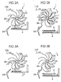
Der Spiralfachstapler weist ein Staplerrad 1 mit spiralförmig hintereinander um eine Rotationsachse angeordneten Fächern auf. Die Rotationsrichtung des Staplerrads ist durch einen Pfeil angedeutet. Dem Staplerrad 1 werden sukzessive Banknoten 98 bis 104 zugeführt.
Ein Ausstreifer 2 greift in üblicher Weise in den Spiralfachstapler ein. Zu diesem Zweck werden die die Banknoten aufnehmenden Fächer durch nebeneinander angeordnete, zueinander beabstandete Staplerradfinger 3 gebildet, zwischen die der Ausstreifer 2 mit geeignet angepassten, nebeneinander angeordneten Ausstreiffingern eingreift. In
Aufgrund der Rotation des Staplerrads 1 und des in das Staplerrad 1 eingreifenden Ausstreifers 2 werden die in dem Staplerrad 1 befindlichen Banknoten gegen den Ausstreifer 2 transportiert und durch diesen nach und nach aus den Fächern des Staplerrads 1 auf eine darunter befindliche Stapelablage 4 ausgestreift. Dadurch bildet sich auf der Stapelablage 4 ein Banknotenstapel 5, dem im in
Wenn die erforderliche Anzahl für den Banknotenstapel 5 von beispielsweise 100 Banknoten erreicht ist, wird der Stapelvorgang unterbrochen, damit der Banknotenstapel 5 der Stapelablage 4 entnommen werden kann, bevor mit dem Stapeln eines nächsten Banknotenstapels begonnen wird. Zu diesem Zweck wird der Ausstreifer 2, wie in
Im Gegensatz zur
Die Bewegung des Ausstreiferteils 2a ist durch geeignete Maßnahmen mit der Rotation des Staplerrads 1 so korreliert, dass der gewünschte Zweck, eine bestimmte Banknote gerade noch auszustreifen und die nächstfolgende Banknote im Staplerrad zu belassen, erreicht wird. Dazu kann das Ausstreiferteil 2a einen separaten, elektronisch gesteuerten Antrieb besitzen oder mechanisch an eine Konturscheibe ankoppelbar sein, wie in
Eine nicht dargestellte Arretierung des zweiten Teils 2b des Ausstreifers 2 zu dessen Fixierung in der in
Der Banknotenstapel 5 wird nun von der Stapelablage 4 entfernt, um die Stapelablage zur Aufnahme des nächstfolgenden Banknotenstapels vorzubereiten. Nachdem die Stapelablage 4 zur Aufnahme eines nächsten Banknotenstapels bereit ist, dreht das Staplerrad 1 solange weiter, bis der zweite Teil 2b des Ausstreifers 2 wieder die Ausstreifposition gemäß
In
Vorzugsweise sind die Stapelablage 4 und die Hilfsstapelablage 6 kammartig ausgebildet. Zunächst wird die Stapelablage 4 mit dem Banknotenstapel 5 abgesenkt, damit die Hilfsstapelanlage 6 darüber positioniert werden kann.Preferably, the
Nachdem der Banknotenstapel 5 von der Stapelablage 4 entfernt wurde, wird sie auf das Niveau der Hilfsstapelablage 6 mit den darauf zwischengestapelten Banknoten 101,109,102,110 etc. derart angehoben, dass die Zinken der beiden Ablagen 4 und 6 kammartig ineinandergreifen und eine gemeinsame Ablageebene bilden. Um eine Kollision der Hilfsstapelablage 6 mit dem aus dem Staplerrad 1 herausbewegten ersten Teil 2a des Ausstreifers 2 zu vermeiden, erfolgt die Zuführung der Hilfsstapelablage 6 beispielsweise in einer Richtung parallel zur Drehachse des Staplerrads.After the
Wie anhand den
Nun kann der erste Teil 2a des Ausstreifers 2 ohne Kollisionsgefahr mit den in dem Staplerrad 1 befindlichen Banknoten in das Staplerrad 1 eingefahren werden. Nachdem der Banknotenstapel 5 von der Ablageplatte 4 entfernt wurde, wird die Stapelablage 4 in der vorbeschriebenen Weise auf das Niveau der Hilfsstapelablage 6 angehoben, und diese kann aus ihrem kammartigen Eingriff mit der Stapelablage 4 herausbewegt werden.Now, the
Claims (8)
- A spiral slot stacker for stacking sheet material, comprising- a stacker wheel (1) with slots spirally disposed one behind the other around a rotational axis for receiving the sheet material,- a stripper (2; 2a, 2b), which has a first movable part (2) which in a strip-out position strips out the sheet material from the slots of the stacker wheel, and- a stack deposit (4) for stacking the sheet material stripped off the slots,wherein the first movable part (2) of the stripper (2) is adapted to be moved out of the strip-out position, while the stacker wheel (1) is rotating, in such a way that the sheet material (100) of one of the slots is stripped out of the stacker wheel and the sheet material (101) of a next slot remains in the stacker wheel, characterized in
that a second movable part (2b) of the stripper (2) is adapted to be locked in the strip-out position and to be moved along with the rotating stacker wheel (1) in the not-locked state. - The spiral slot stacker according to claim 1, characterized by an auxiliary stack deposit (6), which is adapted to be moved over the stack deposit (4) and to be brought to the same level with the stack deposit (4).
- The spiral slot stacker according to claim 2, characterized in that the auxiliary stack deposit (6) and the stack deposit (4) are adapted to engage in a comblike fashion.
- The spiral slot stacker according to one of claims 1 to 3, characterized in that the second part (2b) of the stripper (2) is adapted to be moved back to the strip-out position in an opposite direction to the rotating direction of the stacker wheel (1).
- A bank note processing apparatus comprising one or several spiral slot stackers according to one of claims 1 to 4.
- A method for stacking sheet material by means of a spiral slot stacker having a stacker wheel (1), which has slots spirally disposed one behind the other around a rotational axis for receiving the sheet material (98 to 113), comprising the following steps:- supplying the sheet material into the slots of the stacker wheel,- stripping out the sheet material from the slots of the stacker wheel onto a stack deposit (4) by means of a stripper (2; 2a, 2b) being in a strip-out position for forming a sheet material stack (5),- when a predetermined number of sheets is reached, moving a first movable part (2a) of the stripper (2) out of the strip-out position, while the stacker wheel (1) rotates, in such a way that the last sheet (100) of the predetermined number of sheets is stripped out from the stacker wheel and the sheet material (101) of a next slot remains in the stacker wheel,- preparing the spiral slot stacker for stacking a next sheet material stack, and- moving back the first part (2a) of the stripper (2) to the strip-out position,characterized by the following steps:- releasing a second movable part (2b) of the stripper (2) from the strip-out position and moving along with the rotating stacker wheel (1), when the first part (2a) of the stripper (2) is moved out of the strip-out position,- further supplying sheets into the slots of the stacker wheel, while the second part (2b) of the stripper (2) rotates along with the stacker wheel (1),- locking the second part (2b) of the stripper (2) in the strip-out position, when the spiral slot stacker is prepared for stacking the next sheet material stack, and stripping out the sheet material located in the slots by means of the second part (2b) of the stripper (2), before the first part (1a) of the stripper (2) is moved back to the strip-out position.
- The method according to claim 6, wherein the step of preparing the spiral slot stacker for stacking a next sheet material stack comprises the following steps:- introducing an auxiliary stack deposit (6) over the stack deposit (4) for temporarily stacking the next sheet material stack thereon,- removing the sheet material stack (5) from the stack deposit (4), and- bringing the auxiliary stack deposit (6), with the temporarily stacked sheet material stack, and the stack deposit (4) to the same level, after the sheet material stack (5) was removed from the stack deposit (4).
- The method according to claim 6 or 7, wherein the second part (2b) of the stripper (2) is moved back in an opposite direction as the rotating direction of the stacker wheel (1), so as to lock the said second part (2b) of the stripper (2) in the strip-out position.
Applications Claiming Priority (3)
| Application Number | Priority Date | Filing Date | Title |
|---|---|---|---|
| DE10234970A DE10234970B4 (en) | 2002-07-31 | 2002-07-31 | Method and device for stacking sheet material |
| DE10234970 | 2002-07-31 | ||
| PCT/EP2003/008434 WO2004013025A1 (en) | 2002-07-31 | 2003-07-30 | Method and device for stacking sheet material |
Publications (2)
| Publication Number | Publication Date |
|---|---|
| EP1527007A1 EP1527007A1 (en) | 2005-05-04 |
| EP1527007B1 true EP1527007B1 (en) | 2011-09-14 |
Family
ID=30128564
Family Applications (1)
| Application Number | Title | Priority Date | Filing Date |
|---|---|---|---|
| EP03766368A Expired - Lifetime EP1527007B1 (en) | 2002-07-31 | 2003-07-30 | Method and device for stacking sheet material |
Country Status (9)
| Country | Link |
|---|---|
| US (1) | US7318586B2 (en) |
| EP (1) | EP1527007B1 (en) |
| JP (1) | JP4390145B2 (en) |
| CN (1) | CN100532229C (en) |
| AT (1) | ATE524402T1 (en) |
| AU (1) | AU2003255328A1 (en) |
| DE (1) | DE10234970B4 (en) |
| RU (1) | RU2317935C2 (en) |
| WO (1) | WO2004013025A1 (en) |
Families Citing this family (9)
| Publication number | Priority date | Publication date | Assignee | Title |
|---|---|---|---|---|
| DE102004016109A1 (en) * | 2004-04-01 | 2005-11-03 | Goss International Americas, Inc.(N.D.Ges.D. Staates Delaware) | Bucket wheel delivery for a folder |
| DE102004023312A1 (en) | 2004-05-11 | 2005-12-15 | Giesecke & Devrient Gmbh | Method and device for stacking sheet material |
| DE102004030143A1 (en) * | 2004-06-22 | 2006-01-19 | Giesecke & Devrient Gmbh | Apparatus and method for processing banknotes |
| ITBO20060289A1 (en) * | 2006-04-14 | 2007-10-15 | Tech S R L S | STACKING DEVICE FOR KIDSKINS, NAPKINS AND THE LIKE. |
| CN103562105B (en) * | 2011-03-30 | 2015-12-16 | 光荣株式会社 | The manufacture method of impeller, paper accumulation device and impeller |
| JP5983334B2 (en) * | 2012-11-13 | 2016-08-31 | 沖電気工業株式会社 | Position adjusting device and paper sheet processing device |
| JP2014179033A (en) * | 2013-03-15 | 2014-09-25 | Toshiba Corp | Paper sheet handling apparatus |
| US11084680B1 (en) | 2018-04-05 | 2021-08-10 | Imaging Business Machines Llc | Continually running pocket spindle |
| JP6778782B2 (en) | 2019-04-18 | 2020-11-04 | 日本金銭機械株式会社 | Paper leaf processing equipment, stacking tray, and paper leaf stacking method |
Family Cites Families (20)
| Publication number | Priority date | Publication date | Assignee | Title |
|---|---|---|---|---|
| US3531108A (en) * | 1968-06-04 | 1970-09-29 | Control Data Corp | Document stacker and/or sorter |
| US3851773A (en) * | 1972-07-08 | 1974-12-03 | W Kluge | Stacking device, particularly for newspapers |
| US4501418A (en) * | 1981-02-24 | 1985-02-26 | Tokyo Shibaura Denki Kabushiki Kaisha | Stacking device for paper sheets |
| JPS57138847U (en) * | 1981-02-24 | 1982-08-30 | ||
| JPS58113067A (en) | 1981-12-25 | 1983-07-05 | Toshiba Corp | Collector device of paper sheet |
| JPS5943762A (en) * | 1982-09-03 | 1984-03-10 | Toshiba Corp | Sheet recovery device |
| JPS59172354A (en) * | 1983-03-16 | 1984-09-29 | Toshiba Corp | Paper sheet collecting unit |
| JPS59182156A (en) * | 1983-03-31 | 1984-10-16 | Toshiba Corp | Paper-sheet recovering apparatus |
| JPS59184989A (en) * | 1983-04-04 | 1984-10-20 | 株式会社東芝 | Segmental integrator |
| JPS59223650A (en) * | 1983-05-31 | 1984-12-15 | Toshiba Corp | Sheet accumulating device |
| US5104282A (en) * | 1991-03-11 | 1992-04-14 | Bell & Howell Phillipsburg Co. | Document feeder |
| US5359930A (en) * | 1993-09-17 | 1994-11-01 | Rockwell International Corporation | Device for aligning flies for a printing press |
| US5641156A (en) * | 1993-09-20 | 1997-06-24 | Kabushiki Kaisha Toshiba | Apparatus for inspecting sheet materials and conveying device used therefor |
| DE4437722A1 (en) * | 1994-10-21 | 1996-04-25 | Giesecke & Devrient Gmbh | Method and device for processing banknotes |
| GB9510297D0 (en) * | 1995-05-22 | 1995-07-19 | De La Rue Systems Ltd | Improvements relating to sheet feeding |
| GB9515437D0 (en) * | 1995-07-27 | 1995-09-27 | Rue De Systems Ltd | Sheet feeding apparatus and method |
| US6131903A (en) * | 1999-07-20 | 2000-10-17 | Quad/Tech, Inc. | Signature stripping mechanism |
| ITBO20000475A1 (en) * | 2000-07-31 | 2002-01-31 | Cat System S R L | DEVICE FOR THE SEPARATION OF GROUPS OF SHEETS IN AN APPARATUS FOR THE FORMATION AND BANDING OF GROUPS OF SHEETS, SUCH AS |
| US6877740B2 (en) * | 2003-07-30 | 2005-04-12 | C.G. Bretting Manufacturing Company, Inc. | Starwheel feed apparatus and method |
| JP2005335949A (en) * | 2004-04-30 | 2005-12-08 | Komori Corp | Paper discharge device |
-
2002
- 2002-07-31 DE DE10234970A patent/DE10234970B4/en not_active Expired - Fee Related
-
2003
- 2003-07-30 AU AU2003255328A patent/AU2003255328A1/en not_active Abandoned
- 2003-07-30 AT AT03766368T patent/ATE524402T1/en active
- 2003-07-30 US US10/523,248 patent/US7318586B2/en not_active Expired - Lifetime
- 2003-07-30 CN CNB038180251A patent/CN100532229C/en not_active Expired - Fee Related
- 2003-07-30 WO PCT/EP2003/008434 patent/WO2004013025A1/en active Application Filing
- 2003-07-30 EP EP03766368A patent/EP1527007B1/en not_active Expired - Lifetime
- 2003-07-30 JP JP2004525385A patent/JP4390145B2/en not_active Expired - Fee Related
- 2003-07-30 RU RU2005105689/11A patent/RU2317935C2/en not_active IP Right Cessation
Also Published As
| Publication number | Publication date |
|---|---|
| RU2005105689A (en) | 2006-04-10 |
| AU2003255328A1 (en) | 2004-02-23 |
| EP1527007A1 (en) | 2005-05-04 |
| WO2004013025A1 (en) | 2004-02-12 |
| CN1671611A (en) | 2005-09-21 |
| CN100532229C (en) | 2009-08-26 |
| US20050253322A1 (en) | 2005-11-17 |
| US7318586B2 (en) | 2008-01-15 |
| RU2317935C2 (en) | 2008-02-27 |
| ATE524402T1 (en) | 2011-09-15 |
| JP2005535027A (en) | 2005-11-17 |
| DE10234970B4 (en) | 2005-04-28 |
| DE10234970A1 (en) | 2004-02-12 |
| JP4390145B2 (en) | 2009-12-24 |
Similar Documents
| Publication | Publication Date | Title |
|---|---|---|
| EP0708419B1 (en) | Method and apparatus for processing bank notes | |
| EP1747159B1 (en) | Device and method for stacking sheets | |
| DE3420336C2 (en) | Paper sheet filing device | |
| DE2502222C3 (en) | Device for checking a bundle of banknotes for completeness | |
| DE2758007B1 (en) | Process for controlling the deduction process at a facility for the delivery of individual shipments of different lengths, and corresponding facility | |
| DE3616566A1 (en) | Saddle stitcher | |
| DE3316740A1 (en) | DEVICE FOR GATHERING NEWSPAPERS | |
| DE2553518A1 (en) | SHEET TURNING AND DISPOSING DEVICE | |
| EP2190763B1 (en) | Device for the separation of a sheet product | |
| WO1995009796A1 (en) | Process and device for forming and moving stacks of printed sheets | |
| EP1527007B1 (en) | Method and device for stacking sheet material | |
| DE3008897C2 (en) | Sorter for single sheets of paper fed from a copier or printer | |
| EP0059746B1 (en) | Device for stacking overlapping plane products | |
| DE2747799C2 (en) | ||
| EP1708943A1 (en) | Device for stacking flat, flexible objects | |
| DE60121654T2 (en) | Device for counting and stacking flat products | |
| EP0591099B1 (en) | Method and device for making tied stacks of paper products | |
| DE2651533A1 (en) | DOCUMENT DISPOSAL SYSTEM | |
| DE19940405C2 (en) | Method and apparatus for dispensing a predetermined number of sheets from a group of sheets | |
| EP0185395B1 (en) | Device for separating sheets | |
| EP1149791B1 (en) | Device for removing a test sheet in a delivery apparatus of a sheet printing machine | |
| EP1704107B1 (en) | Spiral-compartment stacker | |
| DE10140101B4 (en) | The sheet stacking | |
| DE3839305A1 (en) | DEVICE FOR THE STACKING OF SINGLE FEEDING SHEETS | |
| DE102016100593B4 (en) | Collection device and method for collecting sheeted goods |
Legal Events
| Date | Code | Title | Description |
|---|---|---|---|
| PUAI | Public reference made under article 153(3) epc to a published international application that has entered the european phase |
Free format text: ORIGINAL CODE: 0009012 |
|
| 17P | Request for examination filed |
Effective date: 20050228 |
|
| AK | Designated contracting states |
Kind code of ref document: A1 Designated state(s): AT BE BG CH CY CZ DE DK EE ES FI FR GB GR HU IE IT LI LU MC NL PT RO SE SI SK TR |
|
| AX | Request for extension of the european patent |
Extension state: AL LT LV MK |
|
| DAX | Request for extension of the european patent (deleted) | ||
| 17Q | First examination report despatched |
Effective date: 20080529 |
|
| GRAJ | Information related to disapproval of communication of intention to grant by the applicant or resumption of examination proceedings by the epo deleted |
Free format text: ORIGINAL CODE: EPIDOSDIGR1 |
|
| GRAP | Despatch of communication of intention to grant a patent |
Free format text: ORIGINAL CODE: EPIDOSNIGR1 |
|
| GRAS | Grant fee paid |
Free format text: ORIGINAL CODE: EPIDOSNIGR3 |
|
| GRAA | (expected) grant |
Free format text: ORIGINAL CODE: 0009210 |
|
| AK | Designated contracting states |
Kind code of ref document: B1 Designated state(s): AT BE BG CH CY CZ DE DK EE ES FI FR GB GR HU IE IT LI LU MC NL PT RO SE SI SK TR |
|
| REG | Reference to a national code |
Ref country code: GB Ref legal event code: FG4D Free format text: NOT ENGLISH |
|
| REG | Reference to a national code |
Ref country code: CH Ref legal event code: EP |
|
| REG | Reference to a national code |
Ref country code: IE Ref legal event code: FG4D Free format text: LANGUAGE OF EP DOCUMENT: GERMAN Ref country code: DE Ref legal event code: R081 Ref document number: 50313952 Country of ref document: DE Owner name: GIESECKE+DEVRIENT CURRENCY TECHNOLOGY GMBH, DE Free format text: FORMER OWNER: GIESECKE & DEVRIENT GMBH, 81677 MUENCHEN, DE |
|
| REG | Reference to a national code |
Ref country code: DE Ref legal event code: R096 Ref document number: 50313952 Country of ref document: DE Effective date: 20111201 |
|
| REG | Reference to a national code |
Ref country code: NL Ref legal event code: VDEP Effective date: 20110914 |
|
| PG25 | Lapsed in a contracting state [announced via postgrant information from national office to epo] |
Ref country code: FI Free format text: LAPSE BECAUSE OF FAILURE TO SUBMIT A TRANSLATION OF THE DESCRIPTION OR TO PAY THE FEE WITHIN THE PRESCRIBED TIME-LIMIT Effective date: 20110914 Ref country code: SE Free format text: LAPSE BECAUSE OF FAILURE TO SUBMIT A TRANSLATION OF THE DESCRIPTION OR TO PAY THE FEE WITHIN THE PRESCRIBED TIME-LIMIT Effective date: 20110914 |
|
| PG25 | Lapsed in a contracting state [announced via postgrant information from national office to epo] |
Ref country code: CY Free format text: LAPSE BECAUSE OF FAILURE TO SUBMIT A TRANSLATION OF THE DESCRIPTION OR TO PAY THE FEE WITHIN THE PRESCRIBED TIME-LIMIT Effective date: 20110914 Ref country code: SI Free format text: LAPSE BECAUSE OF FAILURE TO SUBMIT A TRANSLATION OF THE DESCRIPTION OR TO PAY THE FEE WITHIN THE PRESCRIBED TIME-LIMIT Effective date: 20110914 Ref country code: GR Free format text: LAPSE BECAUSE OF FAILURE TO SUBMIT A TRANSLATION OF THE DESCRIPTION OR TO PAY THE FEE WITHIN THE PRESCRIBED TIME-LIMIT Effective date: 20111215 |
|
| REG | Reference to a national code |
Ref country code: IE Ref legal event code: FD4D |
|
| PG25 | Lapsed in a contracting state [announced via postgrant information from national office to epo] |
Ref country code: IE Free format text: LAPSE BECAUSE OF FAILURE TO SUBMIT A TRANSLATION OF THE DESCRIPTION OR TO PAY THE FEE WITHIN THE PRESCRIBED TIME-LIMIT Effective date: 20110914 Ref country code: CZ Free format text: LAPSE BECAUSE OF FAILURE TO SUBMIT A TRANSLATION OF THE DESCRIPTION OR TO PAY THE FEE WITHIN THE PRESCRIBED TIME-LIMIT Effective date: 20110914 Ref country code: SK Free format text: LAPSE BECAUSE OF FAILURE TO SUBMIT A TRANSLATION OF THE DESCRIPTION OR TO PAY THE FEE WITHIN THE PRESCRIBED TIME-LIMIT Effective date: 20110914 |
|
| PG25 | Lapsed in a contracting state [announced via postgrant information from national office to epo] |
Ref country code: NL Free format text: LAPSE BECAUSE OF FAILURE TO SUBMIT A TRANSLATION OF THE DESCRIPTION OR TO PAY THE FEE WITHIN THE PRESCRIBED TIME-LIMIT Effective date: 20110914 Ref country code: PT Free format text: LAPSE BECAUSE OF FAILURE TO SUBMIT A TRANSLATION OF THE DESCRIPTION OR TO PAY THE FEE WITHIN THE PRESCRIBED TIME-LIMIT Effective date: 20120116 Ref country code: RO Free format text: LAPSE BECAUSE OF FAILURE TO SUBMIT A TRANSLATION OF THE DESCRIPTION OR TO PAY THE FEE WITHIN THE PRESCRIBED TIME-LIMIT Effective date: 20110914 Ref country code: EE Free format text: LAPSE BECAUSE OF FAILURE TO SUBMIT A TRANSLATION OF THE DESCRIPTION OR TO PAY THE FEE WITHIN THE PRESCRIBED TIME-LIMIT Effective date: 20110914 |
|
| PLBE | No opposition filed within time limit |
Free format text: ORIGINAL CODE: 0009261 |
|
| STAA | Information on the status of an ep patent application or granted ep patent |
Free format text: STATUS: NO OPPOSITION FILED WITHIN TIME LIMIT |
|
| PG25 | Lapsed in a contracting state [announced via postgrant information from national office to epo] |
Ref country code: DK Free format text: LAPSE BECAUSE OF FAILURE TO SUBMIT A TRANSLATION OF THE DESCRIPTION OR TO PAY THE FEE WITHIN THE PRESCRIBED TIME-LIMIT Effective date: 20110914 |
|
| 26N | No opposition filed |
Effective date: 20120615 |
|
| REG | Reference to a national code |
Ref country code: DE Ref legal event code: R097 Ref document number: 50313952 Country of ref document: DE Effective date: 20120615 |
|
| BERE | Be: lapsed |
Owner name: GIESECKE & DEVRIENT G.M.B.H. Effective date: 20120731 |
|
| PG25 | Lapsed in a contracting state [announced via postgrant information from national office to epo] |
Ref country code: MC Free format text: LAPSE BECAUSE OF NON-PAYMENT OF DUE FEES Effective date: 20120731 |
|
| REG | Reference to a national code |
Ref country code: CH Ref legal event code: PL |
|
| PG25 | Lapsed in a contracting state [announced via postgrant information from national office to epo] |
Ref country code: LI Free format text: LAPSE BECAUSE OF NON-PAYMENT OF DUE FEES Effective date: 20120731 Ref country code: ES Free format text: LAPSE BECAUSE OF FAILURE TO SUBMIT A TRANSLATION OF THE DESCRIPTION OR TO PAY THE FEE WITHIN THE PRESCRIBED TIME-LIMIT Effective date: 20111225 Ref country code: CH Free format text: LAPSE BECAUSE OF NON-PAYMENT OF DUE FEES Effective date: 20120731 |
|
| PG25 | Lapsed in a contracting state [announced via postgrant information from national office to epo] |
Ref country code: BE Free format text: LAPSE BECAUSE OF NON-PAYMENT OF DUE FEES Effective date: 20120731 |
|
| PG25 | Lapsed in a contracting state [announced via postgrant information from national office to epo] |
Ref country code: BG Free format text: LAPSE BECAUSE OF FAILURE TO SUBMIT A TRANSLATION OF THE DESCRIPTION OR TO PAY THE FEE WITHIN THE PRESCRIBED TIME-LIMIT Effective date: 20111214 |
|
| REG | Reference to a national code |
Ref country code: AT Ref legal event code: MM01 Ref document number: 524402 Country of ref document: AT Kind code of ref document: T Effective date: 20120731 |
|
| PG25 | Lapsed in a contracting state [announced via postgrant information from national office to epo] |
Ref country code: AT Free format text: LAPSE BECAUSE OF NON-PAYMENT OF DUE FEES Effective date: 20120731 |
|
| PG25 | Lapsed in a contracting state [announced via postgrant information from national office to epo] |
Ref country code: TR Free format text: LAPSE BECAUSE OF FAILURE TO SUBMIT A TRANSLATION OF THE DESCRIPTION OR TO PAY THE FEE WITHIN THE PRESCRIBED TIME-LIMIT Effective date: 20110914 |
|
| PG25 | Lapsed in a contracting state [announced via postgrant information from national office to epo] |
Ref country code: LU Free format text: LAPSE BECAUSE OF NON-PAYMENT OF DUE FEES Effective date: 20120730 |
|
| PG25 | Lapsed in a contracting state [announced via postgrant information from national office to epo] |
Ref country code: HU Free format text: LAPSE BECAUSE OF FAILURE TO SUBMIT A TRANSLATION OF THE DESCRIPTION OR TO PAY THE FEE WITHIN THE PRESCRIBED TIME-LIMIT Effective date: 20030730 |
|
| PGFP | Annual fee paid to national office [announced via postgrant information from national office to epo] |
Ref country code: IT Payment date: 20140728 Year of fee payment: 12 |
|
| REG | Reference to a national code |
Ref country code: FR Ref legal event code: PLFP Year of fee payment: 13 |
|
| PGFP | Annual fee paid to national office [announced via postgrant information from national office to epo] |
Ref country code: FR Payment date: 20150730 Year of fee payment: 13 |
|
| PG25 | Lapsed in a contracting state [announced via postgrant information from national office to epo] |
Ref country code: IT Free format text: LAPSE BECAUSE OF NON-PAYMENT OF DUE FEES Effective date: 20150730 |
|
| REG | Reference to a national code |
Ref country code: DE Ref legal event code: R084 Ref document number: 50313952 Country of ref document: DE |
|
| PG25 | Lapsed in a contracting state [announced via postgrant information from national office to epo] |
Ref country code: FR Free format text: LAPSE BECAUSE OF NON-PAYMENT OF DUE FEES Effective date: 20160801 |
|
| REG | Reference to a national code |
Ref country code: FR Ref legal event code: ST Effective date: 20170331 |
|
| REG | Reference to a national code |
Ref country code: DE Ref legal event code: R081 Ref document number: 50313952 Country of ref document: DE Owner name: GIESECKE+DEVRIENT CURRENCY TECHNOLOGY GMBH, DE Free format text: FORMER OWNER: GIESECKE & DEVRIENT GMBH, 81677 MUENCHEN, DE |
|
| REG | Reference to a national code |
Ref country code: GB Ref legal event code: 732E Free format text: REGISTERED BETWEEN 20180118 AND 20180124 |
|
| PGFP | Annual fee paid to national office [announced via postgrant information from national office to epo] |
Ref country code: DE Payment date: 20190731 Year of fee payment: 17 |
|
| PGFP | Annual fee paid to national office [announced via postgrant information from national office to epo] |
Ref country code: GB Payment date: 20190725 Year of fee payment: 17 |
|
| REG | Reference to a national code |
Ref country code: DE Ref legal event code: R119 Ref document number: 50313952 Country of ref document: DE |
|
| GBPC | Gb: european patent ceased through non-payment of renewal fee |
Effective date: 20200730 |
|
| PG25 | Lapsed in a contracting state [announced via postgrant information from national office to epo] |
Ref country code: GB Free format text: LAPSE BECAUSE OF NON-PAYMENT OF DUE FEES Effective date: 20200730 |
|
| PG25 | Lapsed in a contracting state [announced via postgrant information from national office to epo] |
Ref country code: DE Free format text: LAPSE BECAUSE OF NON-PAYMENT OF DUE FEES Effective date: 20210202 |