EP1526992B1 - Scheibenwischvorrichtung, insbesondere für ein kraftfahrzeug - Google Patents
Scheibenwischvorrichtung, insbesondere für ein kraftfahrzeug Download PDFInfo
- Publication number
- EP1526992B1 EP1526992B1 EP03787583A EP03787583A EP1526992B1 EP 1526992 B1 EP1526992 B1 EP 1526992B1 EP 03787583 A EP03787583 A EP 03787583A EP 03787583 A EP03787583 A EP 03787583A EP 1526992 B1 EP1526992 B1 EP 1526992B1
- Authority
- EP
- European Patent Office
- Prior art keywords
- section
- arm
- gear mechanism
- opening
- window
- Prior art date
- Legal status (The legal status is an assumption and is not a legal conclusion. Google has not performed a legal analysis and makes no representation as to the accuracy of the status listed.)
- Expired - Lifetime
Links
- 230000005540 biological transmission Effects 0.000 description 9
- 230000033001 locomotion Effects 0.000 description 4
- 230000008878 coupling Effects 0.000 description 3
- 238000010168 coupling process Methods 0.000 description 3
- 238000005859 coupling reaction Methods 0.000 description 3
- 238000003466 welding Methods 0.000 description 3
- 238000000034 method Methods 0.000 description 2
- 238000004026 adhesive bonding Methods 0.000 description 1
- 230000035515 penetration Effects 0.000 description 1
- 230000003716 rejuvenation Effects 0.000 description 1
- 230000002441 reversible effect Effects 0.000 description 1
Images

Classifications
-
- B—PERFORMING OPERATIONS; TRANSPORTING
- B60—VEHICLES IN GENERAL
- B60S—SERVICING, CLEANING, REPAIRING, SUPPORTING, LIFTING, OR MANOEUVRING OF VEHICLES, NOT OTHERWISE PROVIDED FOR
- B60S1/00—Cleaning of vehicles
- B60S1/02—Cleaning windscreens, windows or optical devices
- B60S1/04—Wipers or the like, e.g. scrapers
- B60S1/32—Wipers or the like, e.g. scrapers characterised by constructional features of wiper blade arms or blades
- B60S1/34—Wiper arms; Mountings therefor
- B60S1/3425—Constructional aspects of the arm
- B60S1/3443—Wiper shafts
-
- B—PERFORMING OPERATIONS; TRANSPORTING
- B60—VEHICLES IN GENERAL
- B60S—SERVICING, CLEANING, REPAIRING, SUPPORTING, LIFTING, OR MANOEUVRING OF VEHICLES, NOT OTHERWISE PROVIDED FOR
- B60S1/00—Cleaning of vehicles
- B60S1/02—Cleaning windscreens, windows or optical devices
- B60S1/04—Wipers or the like, e.g. scrapers
- B60S1/32—Wipers or the like, e.g. scrapers characterised by constructional features of wiper blade arms or blades
- B60S1/34—Wiper arms; Mountings therefor
- B60S1/342—Wiper arms; Mountings therefor with means for temporarily uncoupling the wiper arm from the drive
Definitions
- the invention relates to a windshield wiper device according to the preamble of the independent claim.
- the gearbox is usually designed as a worm gear.
- a non-uniformly translating crank gear which translates the rotational movement of the output shaft into a pendulum motion of the wiper shaft, is disposed downstream of the worm gear between the output shaft and the wiper shaft driving the wiper arm.
- the crank gear is here tuned to the particular vehicle type, which is why and identical engine-gearbox combinations can be used for numerous windscreen wiper systems.
- the windshield wiper device according to the invention with the features of the independent claim has a multi-part design of the output shaft which can be used for many types of vehicles for the same engine-gearbox combination. This is achieved in that only a part of the output shaft is formed as a vehicle-specific section.
- the output shaft has at least a first, non-rotatably connected to the transmission gear portion as a first part and as a second part of a second rotatably connected to the wiper arm arm portion.
- the coupling is designed as a plug-in connection, so that the device is to be mounted in a simple manner at the motor vehicle manufacturer.
- the gear portion has a taper on which is insertable into an opening of the arm portion in order to achieve a low-cost and easy to handle clutch.
- the torque transmission is achieved in that the taper has longitudinal grooves and the opening of the arm portion is caulked against the taper.
- the taper is designed as an external polygon and the opening as réellevielkant, since in such a configuration, the individual sections of the output shaft does not necessarily have to be caulked and still high
- FIG. 1 a windshield wiper device 10 according to the invention is shown in a schematic representation.
- This consists essentially of a drive part 12 which is designed as an electronically reversible electric motor.
- the electric motor 12 drives a not shown armature shaft, which carries at its end remote from the motor a worm, which drives a worm wheel.
- the worm wheel is non-rotatably connected to a cylindrical output shaft 14. Worm and worm wheel form a gear 16, which is enclosed by a gear housing 18.
- the output shaft 14 is formed in several parts and has a projecting from the gear housing 18 gear portion 20 as a first part and a rotatably connected to a wiper arm 22, cylindrical arm portion 24 as a second part, which is closed by a cone 25 which in a Threaded section 27 opens.
- the wiper arm 22 has two ends and is connected to a wiper blade 26 at the end opposite the output shaft 14.
- the transmission 16 need not be limited to a mere worm gear.
- an additional deflection gear can be arranged in the transmission housing 18, which converts the rotational movement of the worm wheel in a pendulum motion.
- FIG. 2 the output shaft 14 of a windshield wiper device 10 according to the invention is shown in an exploded view.
- the gear portion 20 is cylindrical and has at its end remote from the gear housing 18 a taper 28 on.
- the taper 28 is formed such that it is insertable into an opening 30 of the arm portion 24.
- This add the gear portion 20 on the arm portion 24 may be non-positively, so for example, a press fit between the taper 28 and the opening 30 is present.
- Rejuvenation 28 and opening 30 thus form a coupling 31 which serves to connect the gear portion 20 with the arm portion 24.
- the two sections 20, 24 are both cylindrical and have the same diameter D. This closes the gear portion 20 substantially smoothly to the arm portion 24 at.
- the surface of the taper 28 can, for example, also be provided with a knurl.
- the taper 28 is also possible to form the taper 28 as an outer polyhedron, which fits into an inner polyhedron of the opening 30, so that a positive connection between arm portion 24 and gear portion 20 is formed.
- the opening 30 may be provided in the transmission portion 20 and the arm portion 24 have the taper 28.
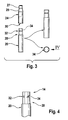
- FIG. 3 is a variation of the output shaft FIG. 2 shown.
- the taper 28 of the gear portion 20 in this case still has a transverse groove 32 and a longitudinal groove 34.
- the opening 30 of the arm portion 24 is designed here as a round bore, but may of course also have to produce a positive fit corresponding guide webs which engage in the longitudinal grooves 34. Are no guide webs provided in the opening 30, the arm portion 24 is rotatably connected by caulking with the gear portion 20. Arm section 24 and gear section 20 can be inserted in this way in the assembly process forces on each other and then caulked by two punches whose stamp surface is cross-shaped, in the crossing region between the transverse groove 32 and longitudinal groove 34 against each other become.
- the torsional strength in the radial direction or the tensile strength of the connection between arm section 24 and gear section 20 in the axial direction is determined.
- FIG. 4 the taper 28 of the gear portion 20 of the output shaft 14 is shown in detail.
- the longitudinal groove 34 and the transverse groove 32 are substantially perpendicular to each other, so that the connection between arm portion 24 and gear portion 20 is reinforced in the axial and radial directions by a cruciform stamp surface.
- the arm portion 24 carries at its end facing away from the opening 30, the cone 25, to which the threaded portion 27 connects.
- the combination of cone 25 and threaded portion 27 is common in wiper shafts 24, so that normal per se known wiper arms 22 are connected to the arm portion 24 in a simple manner.
- the gear portion 20 and the arm portion 24 may also be connected by means of a hexagon or any other polygon.
- additional transverse grooves or longitudinal grooves can be introduced so that the positive connection is supplemented and improved by a frictional connection.
- a cohesive connection between the gear portion 20 and arm portion 24 is possible. This can be done for example by gluing, welding or laser welding.
- the material bond can also be combined arbitrarily with positive and non-positive as shown in the previous embodiments.
- a hexagonal connection can be easily connected in addition to a bond or the connection can be improved by a laser welding process.
Landscapes
- Engineering & Computer Science (AREA)
- Mechanical Engineering (AREA)
- Gears, Cams (AREA)
- Connection Of Motors, Electrical Generators, Mechanical Devices, And The Like (AREA)
- Gear Transmission (AREA)
Description
- Die Erfindung betrifft eine Scheibenwischvorrichtung nach Gattung des unabhängigen Anspruchs.
- Es sind schon zahlreiche Scheibenwischvorrichtungen für Windschutzscheiben von Kraftfahrzeugen bekannt, die ein Antriebsteil, ein Getriebe und ein, das Getriebe umschließendes Gehäuse aufweisen, aus dem eine Abtriebswelle ragt, an der ein Wischerarm befestigt werden kann. Das Getriebe ist hierbei üblicherweise als Schneckengetriebe ausgebildet. Ein ungleichmäßig übersetzendes Kurbelgetriebe, welches die Drehbewegung der Abtriebswelle in eine Pendelbewegung der Wischerwelle übersetzt, ist zwischen der Abtriebswelle und der den Wischerarm antreibenden Wischerwelle dem Schneckengetriebe nachgelagert. Das Kurbelgetriebe ist hierbei auf den jeweiligen Fahrzeugtyp abgestimmt, weshalb und identische Motor-Getriebe-Kombinationen für zahlreiche Scheibenwischanlagen verwendet werden können.
- Zunehmend wird bei modernen Scheibenwischvorrichtungen jedoch auf ein Kurbelgetriebe zwischen Motor und Wischerwelle verzichtet und der Wischerarm direkt mit der Abtriebswelle des Schneckengetriebes verbunden. Bei derartigen Vorrichtungen wird jedoch bei jedem Fahrzeugtyp eine andere Scheibenwischvorrichtung benötigt, da die Eigenschaften und Abmessungen der Abtriebswellen bei den einzelnen Fahrzeugtypen unterschiedlichen Erfordernissen genügen müssen.
- Die erfindungsgemäße Scheibenwischvorrichtung mit den Merkmalen des unabhängigen Anspruchs hat eine mehrteilige Ausbildung der Abtriebswelle die für zahlreiche Fahrzeugtypen für die gleiche Motor-Getriebe-Kombination verwendet werden kann. Dies wird dadurch erzielt, daß jeweils nur ein Teil der Abtriebswelle als fahrzeugspezifischer Abschnitt ausgebildet ist.
- Dokument
EP-A-1215094 offenbart eine Scheibenwischvorrichtung gemäß dem Oberbegriff des Anspruchs 1. - Die Abtriebswelle weist zumindest einen ersten, drehfest mit dem Getriebe verbundenen Getriebeabschnitt als erstes Teil und als zweites Teil einen zweiten, drehfest mit dem Wischerarm verbindbaren Armabschnitt auf.
- Armabschnitt und Getriebeabschnit sind über eine Kupplung miteinander verbunden, so ergibt sich eine kostengünstige und flexible Scheibenwischvorrichtung.
- Die Kupplung ist dabei als Steckverbindung ausgebildet, damit die Vorrichtung in einfacher Weise beim Kraftfahrzeughersteller zu montieren ist.
- Der Getriebeabschnitt weist eine Verjüngung auf der in eine Öffnung des Armabschnittes einführbar ist, um eine kostengünstige und gut handbare Kupplung zu erreichen.
- Der Drehmomentenübertragung wird dadurch erzielt, dass die Verjüngung Längsnuten aufweist und die Öffnung des Armabschnittes gegen die Verjüngung verstemmt ist.
- Weiterhin ist es vorteilhaft, wenn die Verjüngung als Außenvielkant und die Öffnung als Innenvielkant ausgebildet ist, da bei einer derartigen Ausbildung die einzelnen Abschnitte der Abtriebswelle nicht zwingend verstemmt werden müssen und trotzdem eine hohe
- Drehmomentenübertragung gewährleistet ist. Außerdem können die Abschnitte der Abtriebswelle auf diese Weise auch leicht wieder voneinander gelöst werden, was bei einem Austausch der Scheibenwischvorrichtung von Vorteil ist.
- Weist der Armabschnitt einen Konus auf an den sich ein Gewindeabschnitt anschließt, so können gängige Scheibenwischerarme bei der erfindungsgemäßen Scheibenwischvorrichtung verwendet werden.
- Ausführungsbeispiel der Erfindung sind in der Zeichnung dargestellt und in der nachfolgenden Beschreibung näher erläutert. Es zeigen:
-
Figur 1 eine erfindungsgemäße Scheibenwischvorrichtung in schematischer Darstellung, -
Figur 2 eine Abtriebswelle einer erfindungsgemäßen Scheibenwischvorrichtung, -
Figur 3 eine Abtriebswelle einer erfindungsgemäßen Scheibenwischvorrichtung nachFigur 2 in einer Variation und -
Figur 4 der Getriebeabschnitt der Abtriebswelle ausFigur 3 in Detail. - In
Figur 1 ist eine erfindungsgemäße Scheibenwischvorrichtung 10 in schematischer Darstellung gezeigt. Diese besteht im wesentlichen aus einem Antriebsteil 12 welches als elektronisch reversierbarer Elektromotor ausgebildet ist. Natürlich sind auch andere Antriebsarten möglich. Der Elektromotor 12 treibt eine nicht gezeichnete Ankerwelle an, welche an ihrem motorabgewandten Ende eine Schnecke trägt, die ein Schneckenrad antreibt. Das Schneckenrad ist drehfest mit einer zylindrischen Abtriebswelle 14 verbunden. Schnecke und Schneckenrad bilden ein Getriebe 16, welches von einem Getriebegehäuse 18 umschlossen ist. Die Abtriebswelle 14 ist dabei mehrteilig ausgebildet und weist einen, aus dem Getriebegehäuse 18 ragenden Getriebeabschnitt 20 als erstes Teil und einen, drehfest mit einem Wischerarm 22 verbundenen, zylindrischen Armabschnitt 24 als zweites Teil auf, das von einem Konus 25 abgeschlossen ist, der in einen Gewindeabschnitt 27 mündet. Der Wischerarm 22 weist zwei Enden auf und ist an dem der Abtriebswelle 14 entgegengesetzten Ende, mit einem Wischblatt 26 verbunden. - Das Getriebe 16 muss sich natürlich nicht auf ein bloßes Schneckengetriebe begrenzen. So kann auch beispielsweise ein zusätzliches Umlenkgetriebe im Getriebegehäuse 18 angeordnet sein, welches die Drehbewegung des Schneckenrades in eine Pendelbewegung umsetzt.
- In
Figur 2 ist die Abtriebswelle 14 einer erfindungsgemäßen Scheibenwischvorrichtung 10 in eine Explosionsdarstellung gezeigt. Der Getriebeabschnitt 20 ist zylinderförmig ausgebildet und weist an seinem, dem Getriebegehäuse 18 abgewandten Ende eine Verjüngung 28 auf. Die Verjüngung 28 ist derart ausgebildet, dass sie in eine Öffnung 30 des Armabschnitts 24 einführbar ist. Dieses fügen des Getriebeabschnitts 20 an dem Armabschnitt 24, kann kraftschlüssig erfolgen, sodass beispielsweise eine Presspassung zwischen Verjüngung 28 und der Öffnung 30 vorliegt. Verjüngung 28 und Öffnung 30 bilden somit eine Kupplung 31 die zur Verbindung des Getriebeabschnitts 20 mit dem Armabschnitt 24 dient. Die beiden Abschnitte 20, 24 sind beide zylindrisch und besitzen den selben Durchmesser D. Damit schließt sich der Getriebeabschnitt 20 im wesentlichen glatt an den Armabschnitt 24 an. Um eine höhere Verdrehfestigkeit zu erhalten und höhere Drehmomente übertragen zu können, kann die Oberfläche der Verjüngung 28 beispielsweise auch mit einem Rändel versehen werden. - In einer Variation ist es auch möglich, die Verjüngung 28 als Außenvielkant auszubilden, der sich in einen Innenvielkant der Öffnung 30 einfügt, sodass ein Formschluss zwischen Armabschnitt 24 und Getriebeabschnitt 20 entsteht. Prinzipiell kann selbstverständlich auch die Öffnung 30 im Getriebeabschnitt 20 vorgesehen sein und der Armabschnitt 24 über die Verjüngung 28 verfügen.
- In
Figur 3 ist eine Variation der Abtriebswelle ausFigur 2 dargestellt. Die Verjüngung 28 des Getriebeabschnitts 20 weist hierbei noch eine Quernut 32 sowie eine Längsnut 34 auf. Die Öffnung 30 des Armabschnitts 24 ist hier als runde Bohrung ausgeführt, kann aber natürlich auch zur Erzeugung eines Formschlusses entsprechende Führungsstege aufweisen, die in die Längsnuten 34 eingreifen. Sind keine Führungsstege in der Öffnung 30 vorgesehen, so wird der Armabschnitt 24 durch eine Verstemmung mit dem Getriebeabschnitt 20 drehfest verbunden. Armabschnitt 24 und Getriebeabschnitt 20 können auf diese Weise im Montageprozess kräftefrei aufeinander gesteckt werden und danach mittels zweier Stempel, deren Stempelfläche kreuzförmig ausgeführt ist, in den Kreuzungsbereich zwischen Quernut 32 und Längsnut 34 gegeneinander verstemmt werden. Je nach Ausprägung der Quernut 32 und der Längsnut 34 und der Eindringtiefe und Lage der Stempelfläche wird die Verdrehfestigkeit in radialer Richtung bzw. die Zugfestigkeit der Verbindung zwischen Armabschnitt 24 und Getriebeabschnitt 20 in axialer Richtung bestimmt. Sind in der Öffnung 30 Stege vorgesehen, die in die Längsnuten 34 eingreifen, so kann natürlich auf das Verstemmen verzichtet werden. Insbesondere dann, wenn in axialer Richtung keine Zugfestigkeit benötigt wird. - In
Figur 4 ist die Verjüngung 28 des Getriebeabschnitts 20 der Abtriebswelle 14 in Detail gezeigt. Die Längsnut 34 und die Quernut 32 stehen im wesentlichen senkrecht aufeinander, sodass durch eine kreuzförmige Stempelfläche die Verbindung zwischen Armabschnitt 24 und Getriebeabschnitt 20 in axialer und radialer Richtung verstärkt wird. - Der Armabschnitt 24 trägt an seinem der Öffnung 30 abgewandten Ende den Konus 25, an den sich der Gewindeabschnitt 27 anschließt. Die Kombination von Konus 25 und Gewindeabschnitt 27 ist bei Wischerwellen 24 üblich, sodass normale an sich bekannte Wischerarme 22 mit dem Armabschnitt 24 in einfacher Weise verbindbar sind.
- In einer weiteren Variation können der Getriebeabschnitt 20 und der Armabschnitt 24 auch mittels eines Sechskantes oder eines beliebigen anderen Vielkantes verbunden werden. Auch hier können zusätzliche Quernuten oder Längsnuten eingebracht werden, sodass der Formschluss durch einen Kraftschluss ergänzt und verbessert wird. Prinzipiell ist natürlich auch eine stoffschlüssige Verbindung zwischen Getriebeabschnitt 20 und Armabschnitt 24 möglich. Dies kann beispielsweise durch Kleben, Schweißen oder Laserschweißen erfolgen. Natürlich kann der Stoffschluss auch mit Form- und Kraftschluss wie in den vorherigen Ausführungsbeispielen gezeigt beliebig kombiniert werden. So kann beispielsweise eine Sechskantverbindung problemlos zusätzlich mit einer Klebung verbunden werden oder die Verbindung durch ein Laserschweißverfahren verbessert werden.
Claims (3)
- Scheibenwischvorrichtung (10), insbesondere für eine Windschutzscheibe eines Kraftfahrzeugs, umfassend ein Antriebsteil (12), ein Getriebe (16) und ein das Getriebe (16) umschließendes Gehäuse (18) aus dem eine Abtriebswelle (14) ragt, an der ein Wischerarm (22) befestigbar ist, wobei die Abtriebswelle (14) mehrteilig ausgebildet ist, und die Abtriebswelle (14) zumindest einen ersten, drehfest mit dem Getriebe (16) verbundenen Getriebeabschnitt (20) als erstes Teil und einen zweiten, drehfest mit einem Wischerarm (22) verbindbaren Armabschnitt (24) als zweites Teil aufweist, wobei der Getriebeabschnitt (20) und der Armabschnitt (24) über eine Steckverbindung verbindbar sind, dadurch gekennzeichnet, dass der Getriebeabschnitt (20) eine Verjüngung (28) aufweist, die in eine Öffnung (30) des Armabschnittes (24) einführbar ist, und die Verjüngung (28) Längsnuten (34) aufweist und die Öffnung (30) des Armabschnittes (24) gegen die Verjüngung (28) verstemmt ist
- Scheibenwischvorrichtung (10) nach Anspruch 1 dadurch gekennzeichnet, daß die Verjüngung (28) als Aussenvielkant und die Öffnung (30) als Innenvielkant ausgebildet ist.
- Scheibenwischvorrichtung (10) nach Anspruch 1, dadurch gekennzeichnet, daß der Annabschnitt (24) einen Konus (25) aufweist, an den sich ein Gewindeabschnitt (27) anschließt.
Applications Claiming Priority (3)
| Application Number | Priority Date | Filing Date | Title |
|---|---|---|---|
| DE10234097 | 2002-07-26 | ||
| DE2002134097 DE10234097A1 (de) | 2002-07-26 | 2002-07-26 | Scheibenwischvorrichtung, insbesondere für ein Kraftfahrzeug |
| PCT/DE2003/000551 WO2004016481A1 (de) | 2002-07-26 | 2003-02-21 | Scheibenwischvorrichtung, insbesondere für ein kraftfahrzeug |
Publications (2)
| Publication Number | Publication Date |
|---|---|
| EP1526992A1 EP1526992A1 (de) | 2005-05-04 |
| EP1526992B1 true EP1526992B1 (de) | 2009-12-02 |
Family
ID=30010416
Family Applications (1)
| Application Number | Title | Priority Date | Filing Date |
|---|---|---|---|
| EP03787583A Expired - Lifetime EP1526992B1 (de) | 2002-07-26 | 2003-02-21 | Scheibenwischvorrichtung, insbesondere für ein kraftfahrzeug |
Country Status (4)
| Country | Link |
|---|---|
| EP (1) | EP1526992B1 (de) |
| DE (2) | DE10234097A1 (de) |
| ES (1) | ES2336321T3 (de) |
| WO (1) | WO2004016481A1 (de) |
Families Citing this family (6)
| Publication number | Priority date | Publication date | Assignee | Title |
|---|---|---|---|---|
| DE102005027533B4 (de) * | 2005-06-15 | 2009-03-19 | Audi Ag | Scheibenwischeranlage für ein Kraftfahrzeug |
| DE102006013541B4 (de) * | 2006-03-24 | 2011-05-05 | Audi Ag | Scheibenwischeranlage für Kraftfahrzeuge |
| DE102008041997A1 (de) * | 2008-09-11 | 2010-03-18 | Robert Bosch Gmbh | Welle in einer Scheibenwischvorrichtung |
| DE102008043607A1 (de) | 2008-11-10 | 2010-05-12 | Robert Bosch Gmbh | Scheibenwischervorrichtung |
| DE102010029105B4 (de) * | 2009-10-21 | 2018-01-11 | Robert Bosch Gmbh | Scheibenwischervorrichtung |
| FR2960197B1 (fr) * | 2010-05-18 | 2013-01-04 | Peugeot Citroen Automobiles Sa | Mecanisme d'essuyage avec axe modulaire en deux parties |
Family Cites Families (3)
| Publication number | Priority date | Publication date | Assignee | Title |
|---|---|---|---|---|
| DE3523546C1 (de) * | 1985-07-02 | 1986-10-09 | SWF Auto-Electric GmbH, 7120 Bietigheim-Bissingen | Scheibenwischeranlage |
| DE3907968A1 (de) * | 1989-03-11 | 1990-09-13 | Swf Auto Electric Gmbh | Scheibenreinigungsanlage |
| US6568023B2 (en) * | 2000-12-14 | 2003-05-27 | Ford Global Technologies, L.L.C. | Wiper pivot |
-
2002
- 2002-07-26 DE DE2002134097 patent/DE10234097A1/de not_active Withdrawn
-
2003
- 2003-02-21 WO PCT/DE2003/000551 patent/WO2004016481A1/de not_active Ceased
- 2003-02-21 DE DE50312192T patent/DE50312192D1/de not_active Expired - Lifetime
- 2003-02-21 EP EP03787583A patent/EP1526992B1/de not_active Expired - Lifetime
- 2003-02-21 ES ES03787583T patent/ES2336321T3/es not_active Expired - Lifetime
Also Published As
| Publication number | Publication date |
|---|---|
| ES2336321T3 (es) | 2010-04-12 |
| DE50312192D1 (de) | 2010-01-14 |
| DE10234097A1 (de) | 2004-02-05 |
| EP1526992A1 (de) | 2005-05-04 |
| WO2004016481A1 (de) | 2004-02-26 |
Similar Documents
| Publication | Publication Date | Title |
|---|---|---|
| EP2334952B1 (de) | Spindeltrieb mit verdrehsicherung | |
| EP0410487B1 (de) | Notantrieb einer elektromotorisch antreibbaren Antriebseinheit | |
| EP3148860B1 (de) | Lenkwelle für eine kraftfahrzeuglenkung | |
| WO2007144069A1 (de) | Wischanlage für fahrzeugscheiben | |
| EP3253644B1 (de) | Vorrichtung zur einbringung eines hilfsdrehmoments in eine lenkwelle und elektro-mechanische hilfskraftlenkung | |
| DE102018112633B4 (de) | Fingereinheit für eine Roboterhand und Roboterhand | |
| DE102013109284A1 (de) | Lenkwelle für eine Kraftfahrzeuglenkung | |
| EP0802348B1 (de) | Getriebe-Einheit | |
| EP1526992B1 (de) | Scheibenwischvorrichtung, insbesondere für ein kraftfahrzeug | |
| DE102010032995A1 (de) | Notenriegelung einer motorischen Verschließvorrichtung | |
| DE19734815C1 (de) | Antriebsvorrichtung für ein verstellbares Fahrzeugteil | |
| DE10161356A1 (de) | Schraubgerät | |
| EP1664564A1 (de) | Anbindungssystem für eine welle an ein gelenk | |
| EP2187097A1 (de) | Linearantrieb | |
| DE10034041A1 (de) | Wischanlage | |
| DE3342880A1 (de) | Kupplung fuer elektrowerkzeuge | |
| EP4474678B1 (de) | Verstellantrieb mit sicherheitskupplung | |
| EP0644841A1 (de) | Drehschieberventil für hilfskraftlenkungen von kraftfahrzeugen. | |
| DE19803531B4 (de) | Antriebsvorrichtung für ein verstellbares Teil eines Fahrzeuges | |
| EP1480859B1 (de) | Scheibenwischvorrichtung, insbesondere für ein kraftfahrzeug | |
| DE10254129A1 (de) | Elektromotorischer Möbelantrieb zum Verstellen von Teilen eines Möbels relativ zueinander | |
| DE10351484A1 (de) | Elektromotor mit Überlastsicherung und damit ausgestattetes Hilfskraftlenksystem | |
| DE9017796U1 (de) | Manuell betreibbarer Notantrieb | |
| EP1800927B1 (de) | Verdeckantrieb | |
| DE2817190A1 (de) | Kraftuebertragungseinrichtung |
Legal Events
| Date | Code | Title | Description |
|---|---|---|---|
| PUAI | Public reference made under article 153(3) epc to a published international application that has entered the european phase |
Free format text: ORIGINAL CODE: 0009012 |
|
| 17P | Request for examination filed |
Effective date: 20050228 |
|
| AK | Designated contracting states |
Kind code of ref document: A1 Designated state(s): AT BE BG CH CY CZ DE DK EE ES FI FR GB GR HU IE IT LI LU MC NL PT SE SI SK TR |
|
| RBV | Designated contracting states (corrected) |
Designated state(s): CZ DE ES FR GB IT |
|
| 17Q | First examination report despatched |
Effective date: 20080421 |
|
| GRAP | Despatch of communication of intention to grant a patent |
Free format text: ORIGINAL CODE: EPIDOSNIGR1 |
|
| GRAS | Grant fee paid |
Free format text: ORIGINAL CODE: EPIDOSNIGR3 |
|
| GRAA | (expected) grant |
Free format text: ORIGINAL CODE: 0009210 |
|
| AK | Designated contracting states |
Kind code of ref document: B1 Designated state(s): CZ DE ES FR GB IT |
|
| REG | Reference to a national code |
Ref country code: GB Ref legal event code: FG4D Free format text: NOT ENGLISH |
|
| REF | Corresponds to: |
Ref document number: 50312192 Country of ref document: DE Date of ref document: 20100114 Kind code of ref document: P |
|
| REG | Reference to a national code |
Ref country code: ES Ref legal event code: FG2A Ref document number: 2336321 Country of ref document: ES Kind code of ref document: T3 |
|
| PGFP | Annual fee paid to national office [announced via postgrant information from national office to epo] |
Ref country code: ES Payment date: 20100219 Year of fee payment: 8 |
|
| PGFP | Annual fee paid to national office [announced via postgrant information from national office to epo] |
Ref country code: FR Payment date: 20100315 Year of fee payment: 8 |
|
| PGFP | Annual fee paid to national office [announced via postgrant information from national office to epo] |
Ref country code: GB Payment date: 20100219 Year of fee payment: 8 |
|
| PG25 | Lapsed in a contracting state [announced via postgrant information from national office to epo] |
Ref country code: CZ Free format text: LAPSE BECAUSE OF FAILURE TO SUBMIT A TRANSLATION OF THE DESCRIPTION OR TO PAY THE FEE WITHIN THE PRESCRIBED TIME-LIMIT Effective date: 20091202 |
|
| PGFP | Annual fee paid to national office [announced via postgrant information from national office to epo] |
Ref country code: IT Payment date: 20100226 Year of fee payment: 8 |
|
| PLBE | No opposition filed within time limit |
Free format text: ORIGINAL CODE: 0009261 |
|
| STAA | Information on the status of an ep patent application or granted ep patent |
Free format text: STATUS: NO OPPOSITION FILED WITHIN TIME LIMIT |
|
| 26N | No opposition filed |
Effective date: 20100903 |
|
| GBPC | Gb: european patent ceased through non-payment of renewal fee |
Effective date: 20110221 |
|
| REG | Reference to a national code |
Ref country code: FR Ref legal event code: ST Effective date: 20111102 |
|
| PG25 | Lapsed in a contracting state [announced via postgrant information from national office to epo] |
Ref country code: IT Free format text: LAPSE BECAUSE OF NON-PAYMENT OF DUE FEES Effective date: 20110221 |
|
| PG25 | Lapsed in a contracting state [announced via postgrant information from national office to epo] |
Ref country code: FR Free format text: LAPSE BECAUSE OF NON-PAYMENT OF DUE FEES Effective date: 20110228 |
|
| PG25 | Lapsed in a contracting state [announced via postgrant information from national office to epo] |
Ref country code: GB Free format text: LAPSE BECAUSE OF NON-PAYMENT OF DUE FEES Effective date: 20110221 |
|
| REG | Reference to a national code |
Ref country code: ES Ref legal event code: FD2A Effective date: 20120411 |
|
| PG25 | Lapsed in a contracting state [announced via postgrant information from national office to epo] |
Ref country code: ES Free format text: LAPSE BECAUSE OF NON-PAYMENT OF DUE FEES Effective date: 20110222 |
|
| PGFP | Annual fee paid to national office [announced via postgrant information from national office to epo] |
Ref country code: DE Payment date: 20120423 Year of fee payment: 10 |
|
| REG | Reference to a national code |
Ref country code: DE Ref legal event code: R119 Ref document number: 50312192 Country of ref document: DE Effective date: 20130903 |
|
| PG25 | Lapsed in a contracting state [announced via postgrant information from national office to epo] |
Ref country code: DE Free format text: LAPSE BECAUSE OF NON-PAYMENT OF DUE FEES Effective date: 20130903 |