EP1526630A1 - Motor manufacturing method - Google Patents
Motor manufacturing method Download PDFInfo
- Publication number
- EP1526630A1 EP1526630A1 EP03771441A EP03771441A EP1526630A1 EP 1526630 A1 EP1526630 A1 EP 1526630A1 EP 03771441 A EP03771441 A EP 03771441A EP 03771441 A EP03771441 A EP 03771441A EP 1526630 A1 EP1526630 A1 EP 1526630A1
- Authority
- EP
- European Patent Office
- Prior art keywords
- coil
- pole
- motor
- slots
- coils
- Prior art date
- Legal status (The legal status is an assumption and is not a legal conclusion. Google has not performed a legal analysis and makes no representation as to the accuracy of the status listed.)
- Granted
Links
Images















Classifications
-
- H—ELECTRICITY
- H02—GENERATION; CONVERSION OR DISTRIBUTION OF ELECTRIC POWER
- H02K—DYNAMO-ELECTRIC MACHINES
- H02K1/00—Details of the magnetic circuit
- H02K1/06—Details of the magnetic circuit characterised by the shape, form or construction
- H02K1/12—Stationary parts of the magnetic circuit
- H02K1/16—Stator cores with slots for windings
-
- H—ELECTRICITY
- H02—GENERATION; CONVERSION OR DISTRIBUTION OF ELECTRIC POWER
- H02K—DYNAMO-ELECTRIC MACHINES
- H02K15/00—Processes or apparatus specially adapted for manufacturing, assembling, maintaining or repairing of dynamo-electric machines
- H02K15/04—Processes or apparatus specially adapted for manufacturing, assembling, maintaining or repairing of dynamo-electric machines of windings prior to their mounting into the machines
- H02K15/043—Processes or apparatus specially adapted for manufacturing, assembling, maintaining or repairing of dynamo-electric machines of windings prior to their mounting into the machines winding flat conductive wires or sheets
-
- H—ELECTRICITY
- H02—GENERATION; CONVERSION OR DISTRIBUTION OF ELECTRIC POWER
- H02K—DYNAMO-ELECTRIC MACHINES
- H02K15/00—Processes or apparatus specially adapted for manufacturing, assembling, maintaining or repairing of dynamo-electric machines
- H02K15/06—Embedding prefabricated windings in the machines
- H02K15/062—Windings in slots; Salient pole windings
- H02K15/065—Windings consisting of complete sections, e.g. coils or waves
- H02K15/066—Windings consisting of complete sections, e.g. coils or waves inserted perpendicularly to the axis of the slots or inter-polar channels
Definitions
- the present invention relates to a process for manufacturing a motor and, more particularly, to a process for inserting a coil into a motor core.
- a ring-shaped stator core 1 is arranged in a horizontal posture, and a coil 8 is also arranged generally in the horizontal posture axially below the stator core 1.
- the not-shown jig is lifted from below the coil 8 through the inside of the stator core 1, and the inner side end 81 of the coil 8 is hooked and moved upward by the jig.
- the coil 8 is moved to rub the inner circumference of the stator core 1 while changing its state gradually from the horizontal posture to the vertical posture, so that it is inserted into the slots 10 of the stator core 1.
- the coil 8 is inserted, while changing its state, into the slots 10 of the stator core 1, as described hereinbefore.
- this changing course therefore, there arises a state, in which the coil 8 is inserted in an oblique posture.
- the size of the coil 8 has to be given a surplus at least in its vertical length L0.
- the coil 8 takes a state, in which the coil end portion at its upper end portion or its lower end portion bulges more than necessary from the stator core 1.
- the present invention has been conceived in view of those problems of the prior art and contemplates to provide a motor manufacturing process, which can reduce the bulge extents of the coil from the motor core and the axial length of the motor.
- a process for manufacturing a motor which includes a ring-shaped motor core having slots formed in the inner circumference of the motor core and in which coils are inserted and arranged in the slots, characterized by comprising:
- a process for manufacturing a motor which includes a ring-shaped motor core having slots formed in the inner circumference of the motor core and in which coils are inserted and arranged in the slots, characterized by comprising:
- a process for manufacturing a motor which includes a ring-shaped motor core having slots formed in the inner circumference of the motor core and in which coils are inserted and arranged in the slots, characterized by comprising:
- a process for manufacturing a motor which includes a ring-shaped motor core having slots formed in the inner circumference of the motor core and in which coils are inserted and arranged in the slots, characterized by comprising:
- each single-pole coil so generally linearly toward the motor core that it may leave the coil retaining means; to move the adjoining coil insertion portions in the adjoining single-pole coils such that the moving locus may be parallel or may approach the more from the inner circumference side to the outer circumference side; and to move the two coil insertion portions owned by each single-pole coil, such that they may start their movements simultaneously and take the equal velocities or such that they may be simultaneously inserted into the slots.
- each single-pole coil is arranged such that the coil insertion portions may be generally parallel to the inner circumference openings of the slots. Then, the single-pole coil is moved generally linearly to the motor core. Then, the coil insertion portions of the single-pole coil are inserted into the slots.
- the single-pole coil can be inserted by the linear movement with little change in its posture.
- the so-called "linear insertion method (or radial insertion method)" can be executed. Therefore, it is not necessary to enlarge the vertical length of the single-pole coil more than necessary. Therefore, the lengths of the coil insertion portions and the coil end portions of the single-pole coil can be optimized for the state, in which it is mounted in the motor core. Thus, it is possible to reduce the axial length of the parts having the coils mounted on the motor core and accordingly the axial length of the entire motor.
- single-pole coils are moved such that the moving locus the adjoining coil insertion portions in the adjoining may be parallel or may approach the more from the inner circumference side to the outer circumference side. Therefore, the single-pole coil can be easily arranged on the inner circumference side of the motor core, even in the case of using a stator core (or motor core) having a small diameter or a single-pole coil having a large number of turns (or winding number). It is possible to add an effect that the coil inserting step can be easily performed.
- each single-pole coil can move while keeping the distance between the coil insertion portions always at the minimum. From this point, it is unnecessary to add excessive length to the coil end portions.
- each single-pole coil is moved so generally linearly toward the motor core that the moving locus of the winding center point of each single-pole coil may be generally linear.
- the single-pole coils are so arranged on the inner circumference side of the motor core while being retained by the retaining means that the two coil insertion portions owned by each single-pole coil may be individual positioned at an equal distance from the inner circumference openings of the slots.
- the two coil insertion portions owned by each single-pole coil are moved such that they may start to advance simultaneously into the slots and may complete the advancements simultaneously.
- all the coil insertion portions owned by the single-pole coils start their movements simultaneously and take the equal velocities.
- the adjoining coil insertion portions of the adjoining single-pole coils move not only such that the moving locus may be parallel or may approach the more from the inner circumference side to the outer circumference side but also such that the movement starting time, the movements and the movement completing time may be synchronized.
- the crossover lines or the electric lines (or wires) connecting the adjoining single-pole coils can be set to the minimum length so that the motor can be made more compact.
- the motor includes coil groups of a plurality of phases, each of which is composed of a plurality of the single-pole coils
- all the single-pole coils belonging to one phase are arranged in the motor core so that their coil insertion portions of all the single-pole coils are started to move simultaneously and moved at the equal velocities.
- the time period required for the coil inserting step can be shortened to rationalize the steps.
- all the single-pole coils belonging to one phase are desirably connected but may contain the single-pole coil group which is not connected but separated.
- the movements of the single-pole coil at the coil inserting step are done while the angle made between the coil insertion portions and the axial direction of the motor core being kept within 5 degrees. In case the angle made between the coil insertion portions and the axial direction of the motor core exceeds 5 degrees, the effect to reduce the length of the coil end portions may drop.
- the coil inserting step only the single-pole coil is inserted into the slot of the motor core. Specifically, it is preferable not that the coil is moved to the motor core together with the so-called "bobbin" having the coil wound thereon but that the coil is exclusively moved. As a result, the distance between the motor core and each coil (or the single-pole coil) can be reduced to give an advantage that a highly efficient magnetic circuit can be constructed.
- the single-pole coil is moved generally linearly toward the motor core, by applying insertion pressures individually at least to the two coil insertion portions of the single-pole coil.
- the single-pole coil can be linearly moved relatively easily while hardly changing its posture by applying the well-balanced inserting pressures to the two coil insertion portions.
- the single-pole coil is moved generally linearly toward the motor core, by applying insertion pressures individually at least to the two coil end portions of the single-pole coil.
- the linear movement of the single-pole coil can be realized relatively easily by applying the well-balanced inserting pressures to the two coil end portions.
- the single-pole coil is moved generally linearly toward the motor core, by applying insertion pressures individually to a plurality of positions, which are generally symmetric with respect to the winding center point of each single-pole coil.
- the linear movement of the single-pole coil can be realized by applying the well-balanced inserting pressures to those positions.
- the motor is a distributed winding type motor including the ring-shaped motor core having the slots formed in its inner circumference and having coil groups of a plurality of phases, each of which is composed of the single-pole coils making one pole, in which the individual single-pole coils are individually inserted across the two slots and arranged in the motor core and in which the single-pole coils belonging to the coil groups of different phases overlap the coil end portions partially when they are mounted in the motor core.
- the single-pole coils are constructed to have the partially overlapping coil end portions so that the coil end portions or the bulging portions of the coils can be effectively made compact especially by using the linear insertion method.
- the motor core is a stator core.
- the motor core is exemplified by the stator core and the rotor core.
- the case of the stator core is seriously demanded for the compact length in the axial direction, so that the invention is highly effective for the stator core.
- the coils are inserted into the coil retaining grooves of the magazine.
- the coil retaining grooves are formed in the outer circumference of the magazine.
- the coil inserting means is brought into abutment against the coils and is moved from the inside to the outside.
- the coils retained by the coil retaining grooves of the magazine are linearly pushed by the coil inserting means so that they are pushed without changing their postures into the slots of the confronting motor core.
- the linear movement of the coils can be easily executed by the movement of the coil inserting means.
- the coil retaining grooves formed in the magazine for arranging the adjoining coil insertion portions in the adjoining single-pole coils either are formed either in parallel with each other or approach the more from the inner circumference side to the outer circumference side, as described hereinbefore. Therefore, the moving loci of the adj oining coil insertion portions in the adjoining single-pole coils can be easily and reliably made either parallel or to approach each other from the inner circumference side to the outer circumference side.
- the coil inserting means includes insertion blades, which can be inserted into the coil retaining grooves of the magazine, so that the coil insertion portions are moved from the coil retaining grooves into the slots of the motor core by inserting the insertion blades into the coil retaining grooves to advance them from the center toward the outer circumference.
- the insertion blades can be arranged in the coil retaining grooves.
- the insertion blades and the coil insertion portions positioned in the coil retaining grooves can abut against each other all over their faces thereby to realize the stable coil movements.
- the insertions of the insertion blades into the coil retaining grooves may be timed either simultaneously or before and after the arrangement of the magazine in the motor core.
- the insertion blades are inserted from either the surface side face or the back side face of the magazine. As a result, it is possible to simplify the moving mechanism of the insertion blades.
- the coil inserting means includes a pair of split insertion blades, which can be inserted individually from the surface side and the back side of the magazine into the coil retaining grooves, so that the coil insertion portions are moved from the coil retaining grooves into the slots of the motor core by inserting the paired split insertion blades individually from the surface side and the back side of the magazine into the coil retaining grooves to bring them into abutment against the coil insertion portions and by advancing the abutting portions in the direction from the center to the outer circumference.
- the coil inserting means includes a pair of split insertion hooks, which are divided on the surface side and the back side of the magazine, so that the coil insertion portions are moved from the coil retaining grooves into the slots of the motor core by bringing the paired split insertion hooks individually into abutment against the coil end portions protruding to the surface side and the back side of the magazine to advance them in the direction from the center of the magazine to the outer circumference.
- the coil inserting means need not be inserted into the coil retaining grooves so that the coils can be supported more simply and stably from the surface and back of the magazine.
- a provisional shaping step of pushing and deforming the coil end portions is performed by advancing provisional shaping means arranged between the adjoining coil retaining grooves in the direction from the center of the magazine to the outer circumference.
- the provisional shaping step of pushing and deforming the coil end portions or the bulging portions of the coils outward by the provisional shaping means each time the coils are mounted in the motor core.
- the coil end portions can approach the surface of the motor core thereby to further reduce the axial length of the coil end portions.
- the provisional shaping can be executed by using the magazine and the provisional shaping means so that the apparatus and the process can also be simplified.
- the magazine is provided with provisional shaping grooves in juxtaposition to the coil retaining grooves, and in that provisional shaping blades capable of being inserted into the provisional shaping grooves are used as the provisional shaping means, so that the provisional shaping step is performed by inserting the provisional shaping blades into the provisional shaping grooves to advance them in the direction from the center to the outer circumference.
- the apparatus construction can be simplified by combining the provisional shaping grooves and the provisional shaping blades.
- the provisional shaping means includes a pair of split provisional shaping blades split on the surface side and the back side of the magazine, so that the provisional shaping step is performed by advancing the paired split provisional shaping blades on the surface side and the back side of the magazine in the direction from the center of the magazine to the outer circumference.
- the provisional shaping can be stably performed from the surface and back of the coils.
- the coil inserting means includes a pair of split insertion blades split on the surface side and the back side of the magazine, and in that the split insertion blades and the split provisional shaping blades are associated with each other.
- both the coil inserting means and the provisional shaping means are split to the two surface and back face sides of the magazine, more specifically, it is preferable that those existing on the same face side are linked and associated.
- the transfer mechanisms for the coil inserting means and the provisional shaping means can be integrated to simplify the apparatus construction.
- a proper shaping step of shaping the coil end portions is performed by pushing a former having shaping faces for profiling the coil end portions into a desired shape, onto the motor core.
- the provisionally shaped coils can be wholly shaped at once into the desired shape merely by pushing the former onto the motor core. Therefore, it is possible to perform the proper shaping step simply.
- the coil end portions bulging from the motor core can be shaped to approach the motor core so that the aforementioned axial size can be made smaller.
- the formers are provided with cutouts for preventing the interference between the coil inserting means and the provisional shaping means, and in that the formers are pushed onto the motor core while the coil inserting means and the provisional shaping means being kept in the advanced state.
- the coils in the presence of the coil inserting means and the provisional shaping means, the coils can be fixed at its proper shaping step so that the proper shaping can be stably performed.
- the proper shaping step can be consecutively performed subsequent to the completion of the provisional shaping step so that the manufacturing process can be further rationalized.
- the motor is a three-phase DC brushless motor, and in that at the coil inserting step, the single-pole coils of one phase are simultaneously inserted into the slots of the motor core.
- the coils of one phase can be handled all at once by using the magazine.
- all the three phases can be handled so that the works to insert the coils into the motor core can be completed by the three works.
- the magazine can also be exemplified by the take-up jig to be used at the coil forming step.
- the coils are formed by using the take-up jig having the winding frames radially.
- the take-up jig is arranged in the motor core.
- the winding frames owned by the take-up jig are radially arranged.
- a take-up jig having a unique construction including the base holder and the winding frames.
- the winding frame protruding step, the winding step and the winding frame retracting step are performed sequentially for every winding frames.
- the winding step is performed by turning the take-up jig as a whole on the axis of the winding frame protruded. Therefore, the electric line can be fed from one direction, as described hereinbefore, so that it needs not be turned unlike the prior art. Therefore, the single-pole coils can be formed around the winding frames without any torsion in the electric line.
- the winding step is performed after the winding frame protruding step
- the winding frame retracting step is performed after the winding step.
- this change can be made by advancing and retracting the winding frames at the winding frame protruding step and the winding frame retracting step, and no special space for feeding the electric line is needed between the adjoining winding frames. Therefore, the length of the crossover line between the single-pole coils obtained can be suppressed to a sufficiently small value.
- the coil retaining grooves for arranging the adjoining coil insertion portions in the adjoining single-pole coils are arrangedbetween the adjoining winding frames either in parallel with each other or such that they approach more from the inner circumference side to the outer circumference side. Therefore, the moving loci of the adjoining coil insertion portions in the adjoining single-pole coils can be easily and reliably made either parallel or to approach each other from the inner circumference side to the outer circumference side.
- the base holder exhibits a disc shape, and in that the winding frames are arranged to move back and forth along the axes extending radially from the center point of the base holder.
- the take-up jig may be slightly turned as a whole on the center point of the base holder, in case the turning center of the entire take-up jig is to be changed for each winding frame. Therefore, the changing works of the turning center are facilitated when the winding frames are interchanged.
- each winding frame has a sector shape made wider along the axis.
- the shape of the single-pole coil to be formed around each winding frame can be made wider along the axis. Therefore, it is possible to obtain the coil shape easily for the case, in which it is mounted from the inner circumference of the motor core.
- each winding frame in the take-up jig is removably provided with shaping blocks for profiling the shape of the single-pole coil to be wound.
- the shape of the single-pole coil can be easily changed by using the shaping blocks of different shapes.
- These shaping blocks can exhibit the function as the aforementioned positioning tool.
- the take-up jig has such a contour formed of the leading ends of the winding frames while all the winding frames being retracted as is circular around the center point of the base holder.
- the take-up jig is arranged on the inner surface side of the ring-shaped motor core, the clearance between the take-up jig and the inner circumference of the motor core can be reduced to make the movement of the coils smoother.
- separate plates extended from the outer circumference of the base holder are so arranged on the two sides of each winding frame that a predetermined spacing is retained between the separate plates and the winding frame.
- the coil can be arranged in the space of a predetermined distance between the separate plates and the winding frame so that the coil can be retained in the take-up jig while keeping its satisfactory shape.
- the wedge is inserted into the inner circumference opening of the slot so that the electric line (or wire) making the coil may not come out of the slot.
- the wedge used in the motor manufacturing process using the inserter method of the prior art is constructed by folding a sheet of electrically insulating aramid fibers into a C-shape. Moreover, the wedge mounting works are performed simultaneously as the coil is inserted while being moved in the axial direction of the motor core.
- the wedge is not inserted into the slot simultaneously with the insertion of the coil, but the wedge insertion step is executed at a different step after the coil insertion.
- the wedge includes a wide portion arranged in the general portion of the slot, and a convex portion, which has a smaller width size than that of the wide portion, which is protruded from the wide portion and which is arranged in the slot open portion.
- the wedge as formed by folding the aramid fiber sheet of the prior art, has such a low rigidity that its insertion into the slot while pushing out the coil.
- the aforementioned wedge is shaped to have the wide portion and the convex portion. Therefore, the wedge has a shape far superior in the rigidity to that of the wedge prepared by folding the sheet of the prior art. Therefore, the wedge has such a strength as can sufficiently endure the case in which it is solely inserted after the coil was inserted into the slot of the stator core.
- the slot open portion can be made wider than that of the prior art. Therefore, it is possible to improve the insertion of the coil at the coil inserting step.
- the wide portion and the convex portion of the wedge are arranged in the general portion and the slot open portion of the slot of the stator core, respectively.
- the convex portion can engage with the slot open portion so that the wedge can be prevented from turning and coming out of the slot open portion. Therefore, it is possible to keep the stable clogged state of the inner circumference opening of the slot.
- the wedge is molded of a synthetic resin integrally with the wide portion and the convex portion.
- the synthetic resin can be exemplified by various synthetic resins or plastics, if it has the rigidity demanded for the wedge, the electric insulation and the heat resistance of some extent.
- a liquid crystal polymer called the "LCP (Liquid Crystal Polymer)" is excellent in strength characteristics and is especially preferable.
- an inward recessed portion is formed in the surface opposite to the face, as having the convex portion, of the wide portion of the wedge.
- the area of the space in the slot can be enlarged to the extent of the recessed portion so that it can contribute to the improving the filling percentage of the coil.
- At least one of the wide portion and the convex portion at least on longitudinal one end of the wedge is preferably tapered to smaller sizes in width or thickness to the end portion. In this case, even in the presence of the coil already inserted when the wedge is inserted into the slot, the wedge can be inserted while pushing away the coil along that tapered shape, so that the insertion can be improved.
- At least one of the wide portion and the convex portion at least on longitudinal one end of the wedge can also be constructed to have an R-shape by finishing the corners of the end portion into a curved shape. In this case, too, in the presence of the R-shape, it is possible to improve the insertion of the wedge into the slot.
- the wide portion has such a width size that it is arranged while retaining a predetermined clearance between from the inner wall face of the general portion in the slot of the stator core.
- the wedge when the wedge is to be inserted into the slot of the stator core, it does not receive the frictional resistance from the inner wall face of the general portion of the slot to the wedge, so that the inserting workability of the wedge can be better improved.
- the aforementioned clearance is smaller than the size, of which the inner wall face forming the slot open portion of the stator core protrudes from the inner wall face forming the general portion.
- the wide portion can be reliably prevented from passing over and coming out of the slot open portion so that the wedge can be prevented from coming out in the axial direction by the frictional force between the wedge and the protrusion from the inner wall face.
- the clearance is smaller than the diameter of the electric line constructing the coil to be inserted and arranged in the slot of the stator core.
- the electric line of the coil in the slot can be reliably prevented from penetrating to the slot open side more than the wedge, thereby to enhance the effect of suppressing the creeping current.
- a coil inserting apparatus which comprises coil retaining means having coil retaining grooves formed at positions to confront the slots of a motor core and in which coil insertion portions of a single-pole coil are inserted into the coil retaining grooves to regain the single-pole coil in the coil retaining means, so that the single-pole coil is inserted into the slot of the motor core from the coil retaining means while the ring-shaped motor core being arranged on the outer circumference side of the coil retaining means, further comprising:
- the coil retaining means includes one or more provisional shaping grooves between the paired ones of the coil retaining grooves for retaining one single-pole coil; that the coil inserting apparatus further comprises one or more provisional shaping blades disposed between the paired insertion blades corresponding to the paired coil retaining grooves and adapted to be inserted into the provisional shaping grooves; and that the blade driving means is constructed to move the provisional shaping blades forward and backward along the provisional shaping grooves in association with the insertion blades.
- the provisional shaping can be performed simultaneously with the insertion of the single-pole coil.
- the coil inserting apparatus comprises a first arm and a second arm having rocking fulcrums at their lower ends; the insertion blades are connected to the upper end of the first arm; that the provisional shaping blades are connected to the upper end of the second arm; that a first slot and a second slot having slopes at least their portions are formed in the first arm and the second arm; that lifting members to be moved up and down by an actuator are arranged on the inner sides of the first arm and the second arm; that the lifting members have a first pin and a second pin, which can slidably engage with the first slot and the second slot; and that the first arm and the second arm are rocked by moving the lifting members up and down with the actuator thereby to change the engagement positions between the first and second pins and the first and second slots, so that the insertion blades and the provisional shaping blades are advanced or retracted by the rocking motions.
- a motor to be manufactured by the process of this embodiment includes: a ring-shaped motor core (or stator core) 1 (Fig. 9 to Fig. 12) having a plurality of slots 10 formed in its inner circumference; and a coil group of three phases (U-phase, V-phase and W-phase) (Fig. 16 and Fig. 17).
- the coil group of each phase is composed of a plurality of single-pole coils 8 constructing one pole.
- Each single-pole coil 8 is inserted into and arranged in the stator core 1 across the two slots 10.
- the single-pole coils 8 belonging to the coil groups of the different phases have their coil end portions 802 partially overlapping each other when they are mounted in the stator core 1.
- the manufacturing process of this embodiment includes a coil forming step and a coil inserting step.
- the coil forming step forms the coil, which includes: the single-pole coil 8 having two coil insertion portions 801 inserted into the slots 10; and the two coil end portions 802 so arranged outside of the stator core 1 as to join the coil insertion portions 801.
- the single-pole coils 8 are simultaneously moved generally linearly toward the stator core 1 so that their insertion portions 801 of the single-pole coils 8 are simultaneously inserted into the slots 10.
- the adjoining single-pole coils 8 are moved such that the moving loci (e.g., a2 and b1, and b2 and c1 in Fig. 8) before their adjoining coil insertion portions 801 are inserted into the slots 10 may be in parallel with each other.
- the two coil insertion portions 801 of each single-pole coil 8 start their movements simultaneously and take equal velocities.
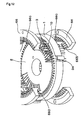
- a magazine 2 which has such a disc shape as can be arranged on the inner side of the inner circumference of the stator core 1 and which is provided in its outer circumference with a plurality of coil retaining grooves 20 for arranging the coil insertion portions 801 of the single-pole coils 8 at positions confronting the slots 10 of the motor core 1, as shown in Fig. 8.
- those e.g., 20A2 and 20B1, and 20B2 and 20C1 in Fig. 8 for arranging the adjoining coil insertion portions 801 of the adjoining single-pole coils 8 are arranged in parallel with each other.
- the coils 8 (or the coil insertion portions 801) are inserted into and arranged in the coil retaining grooves 20, and the magazine 2 is so arranged in the stator core 1 that the coil retaining grooves 20 of the magazine 2 confront the slots 10 of the stator core 1.
- insertion blades 3 as the coil inserting means are caused to abut against the coils 8 and are advanced from the center to the outer circumference of the magazine 2 thereby to move the coils 8 from the coil retaining grooves 20 into the slots 10 of the stator core 1.
- the motor to be manufactured in the invention is a three-phase DC brushless motor.
- the stator core 1 of this embodiment is prepared by laminating ring-shaped electromagnetic steel sheets, and is provided in its inner circumference with seventy two slots 10 in total, as shown in Fig. 9 to Fig. 12 and Fig. 16.
- stator core 1 thirty six single-pole coils 8 in total are divided into three groups of twelve single-pole coils 8 in total, as corresponding to one phase.
- the individual slots 10 are serially numbered from first to seventy second.
- first group one single-pole coil is inserted to form turns through the first slot and the sixth slot.
- another single-pole coil is inserted to form turns through the seventh slot and the twelfth slot.
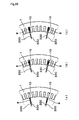
- one single-pole coil is arranged for every six slots. As shown in Fig. 16, therefore, twelve single-pole coils 8 of the coil group belonging to the U-phase are inserted at first into the inner circumference of the stator core 1 and is arranged in the adjoining state.
- the single-pole coils 8 belonging to the second and third groups are arranged with shifts of two and four slots, respectively, in the circumferential direction from the arranged state of the first group. As shown in Fig.
- all the single-pole coils 8 are mounted in the stator core 1 such that the coil end portions 802 of the single-pole coils 8 belonging to the U-phase are partially overlapped from the inner circumference side of the stator core 1 by the coil end portions 802 of the single-pole coils 8 belonging to the V-phase, and such that the coil end portions 802 of the single-pole coils 8 belonging to the V-phase are partially overlapped from the inner circumference side of the stator core 1 by the coil end portions 802 of the single-pole coils 8 belonging to the W-phase.
- the coil end portions 802 of the individual phases are finally packed so compactly at a provisional shaping step and a proper shaping step to be described hereinafter that they are deformed outward from the slots 10.
- the magazine 2 is used to handle one group (of one phase), i.e., the twelve single-pole coils 8 at once so that the thirty six single-pole coils 8 in total are mounted in the stator core 1 by the works of three times.
- the magazine 2 includes: the paired left and right coil retaining grooves 20; a pair of shallowed left and right preparatory grooves 22 positioned between the coil retaining grooves 20; and a pair of left and right provisional shaping grooves 24 positioned between the preparatory grooves 22. If these six grooves are bundled into one group, moreover, these twelve groups are disposed adjacent to each other over the outer circumference of the magazine 2. Moreover, all the adjoining grooves are disposed to confront the slots 10 in the stator core 1 (although partially omitted from Fig. 8 to Fig. 12).
- all the individual preparatory grooves 22 are arranged along the radial directions and are oriented in radially different directions.
- the coil retaining grooves 20 are so arranged in parallel as to make one pair with the coil retaining grooves 20 arranged adjacent to each other for receiving the adjoining single-pole coils 8.
- the paired provisional shaping grooves 24 are arranged in parallel to each other.
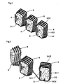
- a winder step is performed for forming the coils.
- the single-pole coils 8 are formed three by three.
- a winding arm 59 for feeding a wire (or an electric line) 88 and winding it on the winding frames 5.
- each winding frame 5 is provided with four upper, lower, left and right pawl portions 51, and in its left and right side faces with cutouts 52 for allowing a later-described transfer device 6 easily to insert thereinto.
- the pawl portions 51 are opened/closed leftward and rightward so that they are opened leftward and rightward to have a larger diameter when they wind the wire.
- each winding frame 5 can be moved forward and backward as a whole and can turn leftward and rightward.
- the winding arm 59 is constructed to feed the wire 88 while turning around the winding frames 5 in the advanced states.
- the turning direction is, moreover, constructed to be changeable.
- the winding frame 5 at the left end is advanced (although not shown), and the wire 88 is fed while the winding arm 59 being turned clockwise around the winding frame 5 at the left end. As a result, the first single-pole coil 8 is formed.
- the left side winding frame 5 is retracted, and the central winding frame 5 is advanced (although not shown). Then, the wire 88 is fed while the winding arm 59 being turned counter-clockwise around the central winding frame 5. As a result, the second single-pole coil 8 is formed.
- the central winding frame 5 is retracted, and the right end winding frame 5 is advanced. Then, the wire 88 is fed while the winding arm 59 being turned again clockwise (in the direction of arrow A) around the right end winding frame 5. As a result, the third single-pole coil 8 is formed.
- the right end winding frame 5 is retracted so that the three winding frames 5 are arranged in a line, as shown in Fig. 2.
- the left and right winding frames 5 are slightly turned outside, as shown in Fig. 3, so that the three single-pole coils 8 are tensed to adjust their shapes.
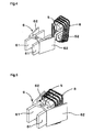
- the three single-pole coils 8 thus formed around the three winding frames 5 are transferred from the winding frames 5 to the magazine 2 by the transfer device 6, as shown in Fig. 4 to Fig. 8.
- the transfer device 6 is provided with two base plates 61 and clamp plates 62 individually arranged outside of the base plates 61. These base plates 61 and clamp plates 62 can be turned or opened/closed in the horizontal directions.
- the transfer device 6 is positioned in parallel to adjust the clearance of the base plates 61 to the position of the clearance between the winding frame 5 and the single-pole coil 8. Moreover, the clamp plates 62 are opened to the left and right from the base plates 61.
- the base plates 61 of the transfer device 6 are inserted into the clearances between the winding frame 5 and the single-pole coil 8, as shown in Fig. 5.
- the clamp plates 62 are then closed to clamp the single-pole coil 8 between the clamp plates 62 and the base plates 61.
- the transfer device 6 is retracted to complete the removal of the single-pole coil 8 from the winding frame 5.
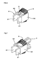
- the transfer device 6 is so arranged that it confronts the outer circumference of the magazine 2, and that the outer side faces 610 of its base plates 61 are generally in parallel with the inner side faces of the coil retaining grooves 20, as shown in Fig. 8.
- the clamp plates 62 are slightly opened to make the single-pole coil 8 movable, and this single-pole coil 8 is pushed and transferred by the not-shown pusher into the coil retaining grooves 20 of the magazine 2.
- the single-pole coil 8 is not pushed deeply into the coil retaining grooves 20 but leaves such clearances between itself and the bottom portions 29 of the coil retaining grooves 20 that the later-described insertion blades 3 may be inserted thereinto.
- the three single-pole coils 8 formed around the three winding frames 5 can be transferred at once to the magazine 2.
- one transfer device 6 can also be used to transfer the single-pole coils 8 one by one.
- the twelve single-pole coils 8 are arranged on the outer circumference of the magazine 2.
- the works from the formations to the transfers of the coils to the magazine 2 can also be rationalized by increasing the facilities of the winding frames 5, the winding arms 59 and the transfer devices 6 to proceed the works in parallel.
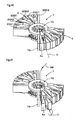
- the magazine 2 is so arranged in the stator core 1 that the coil retaining grooves 20 of the magazine 2 confront the slots 10 of the stator core 1, as shown in Fig. 9.
- the insertion blades 3 are inserted into the clearances in the coil retaining grooves 20 of the magazine 2.
- provisional shaping blades 34 are inserted into the provisional shaping grooves 24 of the magazine 2.
- the insertion blades 3 are advanced in the coil retaining grooves 20 in the directions from the center to the outer circumference, and the provisional shaping blades 34 are advanced in the provisional shaping grooves 24 in the directions from the center to the outer circumference.
- the single-pole coils 8 are pushed by the insertion blades 3 so that they move from the coil retaining grooves 20 to the slots 10 of the stator core 1.
- the upper and lower coil end portions 802, as bulging out of the stator core 1, of the single-pole coils 8 are pushed and deformed outward by the provisional shaping blades 34 so that they are subjected to the provisional shaping treatment.
- the angle made between the individual coil insertion portions 801 and the stator core 1 is kept within 5 degrees even during the movements. Therefore, all the single-pole coils 8 are simultaneously moved generally linearly toward the stator core 1 so that their coil insertion portions 801 of all the single-pole coils 8 are simultaneously inserted into the slots 10.
- the coil retaining grooves 20 of the magazine 2 thus far described, moreover, there are arranged in parallel the coil retaining grooves (e.g., 20A2 and 20B1, and 20B2 and 20C1 in Fig. 8) for arranging the adjoining coil insertion portions 801 in the adjoining single-pole coils 8. Therefore, the coil insertion portions 801 of each single-pole coil 8 move such that their moving loci (e.g., a2 and b1, and b2 and c1 in Fig. 8) before they are inserted into the slots 10 are parallel.
- the coil insertion portions 801 of each single-pole coil 8 move such that their moving loci (e.g., a2 and b1, and b2 and c1 in Fig. 8) before they are inserted into the slots 10 are parallel.
- the insertion blades 3 for pushing the coil insertion portions are completely synchronized from the start to the stop of their movement so that the two coil insertion portions 801 owned by each single-pole coil 8 start their movements simultaneously and move at the equal velocities.
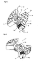
- a second provisional shaping step is performed by using a pair of upper and lower formers 66, which are used in the proper shaping step, too.
- the formers 66 have ring shapes, as shown in Fig. 12, and are provided, on their sides confronting the stator core 1, with shaping faces 660 for profiling the coils into a desired shape.
- the upper and lower individual formers 66 have the tapered shaping faces 660, the inner circumference portions of which protrude toward the stator core 1.
- the formers 66 are constructed such that the coils 8 are shaped outward along the tapered shapes of the shaping faces 660 by advancing the formers 66 to the stator core 1.
- each former 66 is provided with cutouts 665 for preventing the insertionblades 3 and the provisional shaping blades 34 from interfering each other. And, the formers 66 can be pushed onto the stator core 1 while the insertion blades 3 and the provisional shaping blades 34 being advanced.
- the paired upper and lower formers 66 thus constructed are individually advanced from their upper and lower positions and pushed onto the stator core 1.
- the second provisional shaping is performed such that the coil end portions 802, as bulging out from above and below the stator core 1, of the twelve single-pole coils 8 thus arranged in the stator core 1 fall down toward the stator core 1.
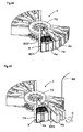
- the coil forming works using the winding frames 5 and the winding arm 59 and the coil transferring works using the transfer device 6 are performed to insert and arrange the twelve single-pole coils 8 of the second group in the magazine 2.
- the magazine 2 is so arranged inside of the stator core 1 that the coil retaining grooves 20 of the magazine 2 confront the slots 10 of the stator core 1.
- the magazine 2 and the stator core 1 are arranged at such circumferentially shifted positions that the coils of the first phase of the first group and the coils of the second group are shifted.
- the movements of the coils 8 using the insertion blades 3 and the provisional shaping using the provisional shaping blades 34 are performed using the movements of the coils 8 using the insertion blades 3 and the provisional shaping using the provisional shaping blades 34.
- the second provisional shaping is performed by using the paired upper and lower formers 66 like the above.
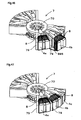
- the twelve single-pole coils 8 of the third group are worked as in the cases of the first and second groups.
- the relative positions of the magazine 2 and the stator core 1 are so circumferentially shifted that the third group (or the third phase) may be shifted with respect to the first group (or the first phase) and the second group (or the second phase).
- the second provisional shaping of the third group is resultantly the proper shaping step.
- the provisional shaping by the provisional shaping blades 34 is directly performed exclusively on the twelve single-pole coils 8 of the third group.
- the shaping to be performed as the second provisional shaping by the formers 66 is performed on all the thirty six single-pole coils 8 so that it becomes the proper shaping step of profiling the entire coil shape.
- the thirty six single-pole coils 8 in total are inserted and arranged in the stator core 1, and the proper shaping is in the completed state.
- this embodiment can execute the so-called "linear insertion method" easily and stably.
- the coils 8 can be linearly inserted without changing their postures into the slots 10. Therefore, it is not necessary to enlarge the vertical length of the coils 8 more than necessary.
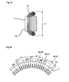
- the vertical size L1 of the coils 8 inserted into the stator core 1 can be made sufficiently shorter than the vertical size L0 of the prior art, as shown in Fig. 68.
- the moving loci of the adjoining coil insertion portions 801 of the adjoining single-pole coils 8 are parallel, as described hereinbefore. Even in case the stator core 1 has a small diameter or uses many turns (or windings) of single-pole coils 8, these single-pole coils 8 can be easily arranged on the inner circumference side of the stator core 1, thereby to add an effect that the coil inserting step can be easily performed.
- each single-pole coil 8 can move while keeping its coil insertion portions at the minimum distance at all times. From this point, it is unnecessary to add excessive length to the coil end portions.
- the provisional shaping grooves 24 are formed in the magazine 2 so that the provisional shaping is performed by the movements of the provisional shaping blades 34.
- the provisional shaping can be easily performed to push and deform the coil end portions 802 of the coil outward, each time each single-pole coil 8 is mounted in the stator core 1.
- these works can be done simultaneously with the transfer of the coils, thereby to simplify the device and the step.
- the formers 66 are used and pushed onto the stator core 1 to perform the second provisional shaping and the proper shaping of the coils 2.
- all the provisionally shaped coils can be shaped all at once into a desired shape merely by pushing the formers 66 onto the stator core 1.
- the coil end portions bulging from the stator core 1 can be shaped to approach the stator core 1 so that the aforementioned axial size can be made smaller.
- the formers 66 are provided with the aforementioned cutouts so that they can be pushed onto the stator core 1 while the insertion blades 3 and the provisional shaping blades 34 being advanced. Therefore, the second provisional shaping and the proper shaping by the formers 66 can be executed consecutively of the insertion and provisional shaping of the coils 8 into the stator core 1, as described hereinbefore, so that the manufacturing process can be rationalized.
- the insertion blades 3 are used as the coil inserting means, and the provisional shaping blades 34 are used as the provisional shaping means.
- these blades could be replaced by the split insertion blades or the split insertion hooks and the split provisional shaping blades or the split provisional shaping hooks, which are split on the surface side face and the back side face of the magazine 2.
- the split insertion blades or the split insertion hooks and the split provisional shaping blades or the split provisional shapinghooks couldbe integrated on the surface side face and the back side face of the magazine 2, thereby to simplify the device.
- this embodiment has exemplified the three-phase DC brushless motor, but process thus far described could be applied to a motor of another structure.
- a coil inserting apparatus for inserting the coils from the magazine 2 of Embodiment 1 into the stator 1 is shown more detail in Fig. 18 and Fig. 19.
- the coil inserting apparatus 9 of this embodiment is, as shown Fig. 18, provided with an upper plate portion 92, which is fixed through the not-shown posts extended from a bottom plate portion 91, and a magazine receiving rest 93 disposed above the upper plate portion 92 for placing the magazine 2 thereon.
- the magazine receiving rest 93 is composed of a flange portion 931, and a central mandrel 932 having a column shape of smaller diameter than that of the flange portion 931.
- the bottom plate portion 91 is provided with a plurality of first arms 94 arranged to rock on fulcrums 941, and a plurality of second arms 95 arranged to rock on fulcrums 951.
- first arms 94 are provided with the insertion blades 3 at their upper ends
- second arms 95 are provided with the provisional shaping blades 34 at their upper ends.
- the first arm 94 is provided with a slot 942, which can engage with a pin 963 formed on a lifting plate 961.
- the second arm 95 is provided with a slot 952, which can engage with a pin 964 formed on a second lifting plate 962.
- the lifting plate 961 is connected to a cylinder 971, a lifting rod 972, a base plate 973, a connecting rod 974 and so on, which are arranged above the bottom plate portion 91, so that it is moved up and down as the lifting rod 972 is driven upward and downward by the cylinder 971.
- the slots 942 and 952 formed in the first arm 94 and the second arm 95 have sloped slot portions.
- the engaging positions between the pins 963 and 964 and the slots 942 and 952 are shifted by the vertical movements of the pins 963 and 964, moreover, the first arm 94 and the second arm 95 rock on the fulcrums 941 and 951.
- the shapes of the slot 942 of the first arm 94 and the slot 952 of the second arm 95 are slightly changed to give different rocking strokes to the first arm 94 and the second arm 95.
- each first arm 94 is arranged with the two insertion blades 3 in parallel so that these two insertion blades 3 are moved together in parallel in the rocking direction of the first arm 94.
- the rocking directions of all the first arms 94 are taken along a radial direction A through the center of teeth 15 positioned between the two slots 10 of the stator 1.
- each second arm 95 is likewise arranged with the two provisional shaping blades 34 in parallel so that these two provisional shaping blades 34 are moved together in parallel in the rocking direction of the second arm 95.
- the rocking directions of all the second arms 95 are taken along a radial direction B through the center of the teeth 15 positioned between the two slots 10 of the stator 1.
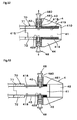
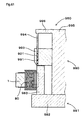
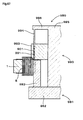
- this coil inserting apparatus 9 is that the angle of inclination ⁇ of the insertion blades 3 at the rocking motion starting position of the insertion blades 3 with respect to the vertical direction is set within 5 degrees, and that the angle of inclination at the rocking motion ending position with respect to the vertical direction is set at 0 degrees, as shown in Fig. 18.
- all the single-pole coils 8 can be simultaneously moved generally linearly toward the stator core 1 while the angle made between the coil insertion portions 801 to abut against the insertion blades 3 and the slots 10 of the stator 1 being always kept within 5 degrees.
- the two adjoining insertion blades 3 are arranged in parallel and push the adjoining coil insertion portions 801 of the adjoining single-pole coils 8.
- the adjoining coil insertion portions 801 can be pushed by the insertion blades 3 to move in parallel in the two coil retaining grooves 20 arranged in parallel, as described hereinbefore, and the pushing points are always kept in parallel.
- the adjoining coil insertion portions 801 of the adjoining single-pole coils 8 can be moved remarkably easily in parallel with each other until they reach the slots 10, thereby to make their moving loci parallel.
- This embodiment presents another example of the aforementioned insertion blades, as shown in Fig. 20.
- an insertion blade 302 of this embodiment is formed into a generally L-shape, which is composed of a horizontally extending base portion 303 and a vertically extending vertical blade portion 304. Moreover, this vertical blade portion 304 has an abutment face 305 formed as a vertical face. And, the insertion blade 302 is constructed such that the vertical blade portion 304 is moved back and forth by moving the base portion 303 horizontally with its abutment portion 305 being kept vertical.
- the angle made between the coil insertion portion 801 and the axial direction of the slot core 1 can be kept substantially at 0, as shown in Fig. 20 (a), not only at the time of abutting against the coil insertion portion 801 but also at the instant when the insertion of the stator core 1 into the slots 10 is completed.
- this embodiment uses a pair of upper and lower split insertion blades 320 and 330 as the insertion blades.
- the split insertion blades 320 and 330 of this embodiment are a pair of upper and lower strip shapes, as shown in Fig. 21, and have such tapered portions 325 and 335 on one-side faces of their leading end sides as are arranged to have their leading ends in a confronting relation.
- Fig. 21 presents views, in which the motions of the split insertion blades 320 and 330 and the single-pole coils 8 are taken in the radial direction of the stator core 1.
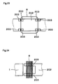
- Fig. 22 presents explanatory views, which correspond to the individual actions of Fig. 21 and in which the width sizes of the portions, as contacting with the coils 8, of the split insertion blades 320 and 330, are taken and shown in the axial direction of the stator core 1.
- Fig. 21 and Fig. 22 proceed from (a) to (c), the split insertion blades 320 and 330 approach and overlap each other.
- the width sizes of the abutting portions against the single-pole coils 8 grow gradually larger along the tapered portions 325 and 335 so that the single-pole coils 8 are gradually pushed into the slots 10 of the stator core 1.
- the insertion pressure to be applied to the single-pole coil 8 is applied to the four portions which are generally symmetric with respect to the winding center point of the single-pole coil 8, as will be shown in Fig. 29 described herein after.
- the single-pole coil 8 can be moved linearly from the state, in which it is arranged generally in parallel with the slot 10, while keeping its posture substantially.
- this embodiment adopts a magazine 202 having a structure different from that of Embodiment 1.
- the magazine 202 of this embodiment has supporting rod portions 203 for forming coil retaining grooves to retain the single-pole coils 8.
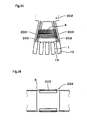
- the coil inserting step can be executed as in Embodiment 1 by retaining the single-pole coils 8 in the manner shown in Fig. 23 and Fig. 24.
- this embodiment adopts a magazine 204 having a construction different from that of the magazine in Embodiment 1.
- the magazine 204 of this embodiment is provided with a pair of upper and lower magazine plates 205 for every one pole, which extend from the radially outer side to the inner circumference side.
- the single-pole coils 8 of one pole are retained by the magazine plates 205 of the magazine 204 and are mounted up and down in the axial direction of the stator core 1. And, the single-pole coils 8 are pushed and moved in the slots 10 by the insertion blades or the like.
- the coil inserting step can be executed by the actions to extract the magazine plates 205 retaining the individual single-pole coils 8, either one by one or simultaneously in plurality to the radially outer side.
- this embodiment presents an example of the position, at which the insertion pressure is applied to the single-pole coil 8 at the coil inserting step.
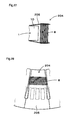
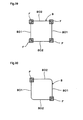
- Fig. 29 shows an example, in which the insertion pressure is applied to a plurality of positions substantially symmetric with respect to the winding center point of the single-pole coil 8, that is, pushed regions F of four corners at the boundary portions between the coil insertion portions 801 and the coil end portion 802 of the single-pole coil 8.
- Fig. 30 shows an example, in which the insertion pressure is applied to a plurality of positions substantially symmetric with respect to the winding center point of the single-pole coil 8, that is, pushed regions F of two diagonal ones of the four corners at the boundary portions between the coil insertion portions 801 and the coil end portion 802 of the single-pole coil 8.
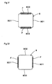
- Fig. 31 and Fig. 34 show an example, in which the insertion pressure is applied to the pushed regions F of the two coil end portions 802 of the single-pole coil 8, individually.
- Fig. 32 and Fig. 33 show an example, in which the insertion pressure is applied to the pushed regions F of the two coil insertion portions 801 of the single-pole coil 8, individually.
- the single-pole coil 8 can be linearly moved while the angle made between the coil insertion portions 801 of the single-pole coil 8 and the slots 10 being kept within 5 degrees.
- Fig. 29 to Fig. 34 just present the examples, and it is quite natural that the pushed regions F or the applied positions of the insertion pressure could be further modified.
- this embodiment presents an example, in which split insertion hooks can be used as the coil inserting means in place of the insertion blades 3 of Embodiment 1.
- Fig. 35 shows one of a pair of split insertion hooks 350, which are split into the surface side and the back side of the magazine.
- These split insertion hooks 350 have an L-shaped section to be hooked on the two end portions of the coil end portion 801 so that they apply the insertion pressure to the pushed regions F of the four corners, as shown in Fig. 29.
- Fig. 36 shows one of a pair of split insertion hooks 352, which are split into the surface side and the back side of the magazine. These split insertion hooks 352 have a C-shaped section to be hooked on the entirety of the coil end portion 801 so that they apply the insertion pressure, as shown in Fig. 34.
- the coil inserting step like that of Embodiment 1 can also be executed by using those split insertion hooks.
- the coil forming step is executed by using a magazine (or a take-up jig) 7, which has a special structure to function as the take-up jig.
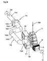
- the take-up jig (or the magazine) 7 and a turning device 74 as a coil forming device for forming a motor coil (as referred to Fig. 50), which is prepared by juxtaposing three adjacent single-pole coils 8 turned in a loop shape with the electric line 88, as shown in Fig. 37 and Fig. 38.
- the take-up jig 7 is provided with a base holder 70 and a plurality of winding frames 4 arranged on the outer circumference of the base holder 70.
- the individual winding frames 4 are arranged to move to and from the base holder 70 and are constructed such that any of the winding frames 4 may protrude from the remaining ones.
- the turning device 74 is constructed to turn the take-up jig 7 as a whole on the longitudinal axis C of the winding frame 4 protruded.
- the base holder 70 presents a disc shape. Specifically, the base holder 70 has a pair of upper and lower ring-shaped plates 71 and 72, which are provided with central through holes 710 and 720, respectively, and a plurality of positioning holes 712 and 722 around the central through holes 710 and 720. These central through holes 710 and 720and the positioning holes 712 and 722 around there are provided for determining the engaging positions with the turning device 74, as will be described hereinafter.
- the paired upper and lower ring-shaped plates 71 and 72 are connected through separate plates 79, which are arranged in the radial direction extending from the centers of those ring-shaped plates 71 and 72.
- the four separate plates 79 are arranged at a pitch of an internal angle of 15 degrees, and the four separate plates 79 are further arranged at the diagonal positions at the pitch of the internal angle of 15 degrees.
- the winding frames 4 In the spaces of the internal angle of about 15 degrees between the adjoining separate plates 79, moreover, there are individually arranged the winding frames 4.
- the six winding frames 4 in total are provided by arranging the three adjoining winding frames 4 at the diagonal positions.
- the take-up jig 7 of this embodiment is constructed such that the separate plates 79 and the winding frames 4 can be further arranged at empty positions in the outer circumference of the disc-shaped base holder 70, so that it can be provided with the twelve winding frames 4 at the maximum.
- the winding frames 4 are arranged such that they can move back and forth along the axes extending radially from the center point of the base holder 70. Moreover, the individual winding frames 4 have a sector shape, in which they are widened along the aforementioned axis.
- each winding frame 4 has a frame body portion 42, which is generally formed in a sector shape in view of the front face and the back face, if these front and back faces are those parallel to the ring-shaped plates 71 and 72 of the base holder 70, and which is provided with a cutout 420 at its central portion. Moreover, the frame body portion 42 is provided on its two side faces with stepped portions 425 for positioning the single-pole coil 8 formed.
- shaping blocks 43 and 44 for profiling the shapes of the single-pole coil to be wound.
- These shaping blocks 43 and 44 are also generally formed in a sector shape, which is provided with cutouts 430 and 440 at their central portions.
- the shaping blocks 43 and 44 are fixed on the frame body portion 42 by driving the not-shown screws.
- the shaping blocks 43 and 44 of this embodiment are made the thicker as they come the closer to the inner circumference side from the outer circumference side, so that the single-pole coil to be shaped may become the higher toward the inner circumference side.
- the frame body portion 42 is provided with a rectangular through hole 429 in the axial direction from the cutout 420 to the base holder 70.
- rod holes 428 are formed as circular through holes.
- the winding frame 4 is arranged to move back and forth in the base holder 70 by fixing a guide plate 41 through the through hole 429 in the base holder 70.
- the guide plate 41 is provided with a root end portion 415 to be fixed in the base holder 70, and a leading end portion 410, which is vertically large-sized generally in a T-shape to regulate the advanced position of the winding frame 4.
- the root end portion 415 of the guide plate 41 is inserted into the through hole 429 opened in the bottom portion of the cutout 420 of the frame body portion 42, and rods 45 carrying springs 46 are inserted into the rod holes 428 formed at the upper and lower portions of the through hole 429 in the frame body portion 42.
- the root end portion 415 of the guide plate 41 is clamped and fixed between the paired upper and lower ring-shaped plates 71 and 72 of the base holder 70, and the two rods 45 are fixed at their one-side ends on the ring-shaped plates 71 and 72 and at their other ends on the leading end portion 410 of the guide plate 41.
- the winding frame 4 is fixed such that it can move back and forth with respect to the base holder 70.
- the winding frame 4 is provided in its upper and lower portions with positioning pins 48, which can move their leading end portions 481 forward and backward by pinching and operating their head portions 480.
- the guide plate 41 is provided with pin holes 418 and 419, which can engage with the pin leading end portions 481. While the pin leading end portions 481 of the positioning pins 48 being made to engage with the pin holes 418, as shown in Fig. 51, the winding frame 4 is retracted and kept in the state close to the base holder 70.
- the positioning pins 48 are retracted to release the pin leading end portions 481 and the pin holes 418 from the engaging state so that the winding frame 4 is advanced against the springs 46. As shown in Fig. 53, moreover, the positioning pins 48 are advanced again to bring the pin leading end portions 481 into engagement with the pin holes 419. As a result, the winding frame 4 is advanced in its axial direction and is fixed at a position spaced from the base holder 70.
- each winding frame 4 On the two sides of each winding frame 4 thus arranged, there exist the separate plates 79, which are extended from the outer circumference of the base holder 70. Moreover, the separate plate 79 and the winding frame 4 are spaced at a predetermined distance functioning as the later-described coil retaining groove 20.
- the coil retaining grooves 20 As shown in Fig. 40, there are arranged in parallel the coil retaining grooves (e.g., 20A2 and 20B1, or 20B2 and 20C1 in Fig. 40) for arranging the adjoining coil insertion portions 801 in the adjoining single-pole coils 8.
- the coil retaining grooves e.g., 20A2 and 20B1, or 20B2 and 20C1 in Fig. 40
- the contour formed of the leading ends of all the winding frames 4 retracted is a circular shape around the center point of the base holder 70.
- the take-up jig 7 of this embodiment is shaped such that the individual winding frames 4 may be arranged to confront the inner circumference of the later-described stator core.
- the turning device 74 of this embodiment is provided with a straight portion 741 extending from the not-shown drive shaft, and a bent portion 76 connected to the straight portion 741 through flanges 751 and 752, and the bent portion 76 is provided at its leading end with a flange 77 for connecting the bent portion 76 to the take-up jig 7.
- the bent portion 76 is provided with: a first portion 761 extending on the common axis of the straight portion 741; a second portion 762 bent at 90 degrees and extended from the first portion; a third portion 763 bent at 90 degrees from the second portion 762 and extended in parallel with the straight portion 741; and a fourth portion 764 bent at 90 degrees from the third portion 763.
- the aforementioned connecting flange 77 is arranged at the leading end of the fourth portion 764.
- the connecting flange 77 is so positionally arranged that the center point of the base holder 70 in the thickness direction and in the radial direction may be located on the axis of the straight portion 741.
- the circumferentially fixed position of the connecting flange 77 to the take-up jig 7 can be so suitably changed that the axis C of the winding frame 4 may be aligned with the turning center C2 of the straight portion 741 of the turning device 74.
- a winding frame protruding step is performed to advance the first winding frame 4a from that state so as to protrude the same from the remaining winding frames 4, as shown in Fig. 41.
- the winding frame 4a is released from the fixed state, in which it is fixed at the retracted position by the positioning pins 48 (Fig. 51 to Fig. 53), and the winding frame 4a is advanced against the springs 46.
- the winding frame 4a is fixed again at its advanced position by the positioning pins 48.
- the electric line 88 is fed in one direction from above, as shown in Fig. 41, and its leading end is fixed on the take-up jig 7.
- a special fixing device may be used to fix the leading end at a predetermined position, or the leading end may be tied to an arbitrary position of the take-up jig 7. The latter method is adopted in this embodiment.
- the protruded winding frame 4a is fed in one direction with the electric line 88, and the turning device 74 is driven to perform a winding step of turning the take-up jig 7 as a whole on the axis C of the winding frame 4a.
- the electric line 88 is wound around the protruded winding frame 4a, thereby to complete the formation of the first single-pole coil 8, as shown in Fig. 43.
- the winding frame 4a is fixed at the retracted position by operating the positioning pins 48 (Fig. 51 to Fig. 53) again.
- the single-pole coil 8 wound around the winding frame 4a takes the state, in which its coil end portions 802 positioned above and below the loop are uncovered to the surface side and back side of the winding frame 4 and in which the coil insertion portions 801 positioned on the left and right are housed in the clearances between the separate plates 79 and the winding frame 4.
- a second winding frame 4b adjacent to the first winding frame 4a having the single-pole coil 8 formed thereon is advanced along the axis C to protrude from the outer sides of the remaining winding frames 4 and is fixed like before at the advanced position.
- the engaging position between the take-up jig 7 and the turning device 74 is changed to align the turning center of the turning device 74 and the axis of the second winding frame 4b.
- a crossover line 885 leading from the single-pole coil 8 retained by the first winding frame 4a is turned over to below the second winding frame 4b, and the succeeding electric line 88 is fed like before from above in one direction.
- the protruded winding frame 4b is fed with the electric line 88 in one direction, and there is performed the winding step of turning the take-up jig 7 as a whole on the axis C of the winding frame 4b.
- the turning direction at this time is reversed from that of the case of the first winding frame 4a.
- the electric line 88 is wound around the protruded winding frame 4b, as shown in Fig. 47, thereby to complete the formation of the second single-pole coil 8 having its wound direction reversed from that of the first single-pole coil 8.
- the second winding frame 4b having the single-pole coil 8 formed thereon is retracted and is fixed like before at the retracted position.
- the second single-pole coil 8 wound around the winding frame 4b takes the state, in which its coil end portions 802 positioned above and below the loop are uncovered to the surface side and back side of the winding frame 4 and in which the coil insertion portions 801 positioned on the left and right are housed in the clearances between the separate plates 79 and the winding frame 4.
- a third winding frame 4c adjacent to the second winding frame 4b is advanced along the axis C to protrude from the outer sides of the remaining winding frames 4 and is fixed like before at the advanced position.
- the engaging position between the take-up jig 7 and the turning device 74 is changed to align the turning center C2 (Fig. 37 and Fig. 38) of the turning device 74 and the axis C of the third winding frame 4c.
- the electric line 88 succeeding to the crossover line 885 leading from the single-pole coil 8 retained by the second winding frame 4b is fed like before from above in one direction.
- the protruded winding frame 4c is fed with the electric line 88 in one direction, and there is performed the winding step of turning the take-up jig 7 as a whole on the axis C of the winding frame 4c.
- the turning direction at this time is reversed from that of the case of the second winding frame 4c.
- the electric line 88 is wound around the protruded winding frame 4c, as shown in Fig. 49, thereby to complete the formation of the third single-pole coil 8 having its wound direction reversed from that of the second single-pole coil 8.
- the third winding frame 4c having the single-pole coil 8 formed thereon is retracted and is fixed like before at the retracted position.
- the coil insertion portions 801 of the third single-pole coil 8 formed around the winding frame 4c are also housed in the clearances between the separate plates 79 and the winding frame 4.
- the coil, in which the three single-pole coils 8 are juxtaposed to each other with the alternately reversed winding directions can be formed by a procedure similar to the aforementioned one.
- the take-up jig 7 having the aforementioned structure composed of the base holder 70 and the winding frames 4 and the turning device 74.
- the winding frame protruding step, the winding step and the winding frame retracting step are performed sequentially on the individual winding frames.
- the winding step is performed by turning the take-up jig as a whole on the axis C of the protruded winding frame 4.
- the electric line 88 can be fed in one direction so that the single-pole coil 8 can be formed around the winding frame 4 without any torsion of the electric line 88.
- the winding step follows the winding frame protruding step, and is followed by the winding frame retracting step.
- this change can be made by advancing and retracting the winding frame 4 at the winding frame protruding step and at the winding frame retracting step, and no special space for feeding the electric line need be established between the adjoining winding frames 4. Therefore, the length of the crossover line 885 between the single-pole coils 8 obtained can be reduced to a sufficient short length.
- each winding frame 4 of the take-up jig 7 is generally given the sector shape, and the shaping blocks 43 and 44 are arranged on the surface side and back side of the winding frame 4.
- the shaping blocks 43 and 44 are thickened in the inward direction as described above. In the single-pole coil 8 wound around the winding frame 4, therefore, the shapes of the electric line loops composing itself are changed along the axis C of the winding frame 4.
- the electric line loops composing the single-pole coil 8 become wider in the outward direction along the sector-shaped winding frame 4 and become lower along the shape of the shaping blocks 43 and 44.
- the arrangement of the coil end portions 802 as will be described hereinafter, when the coil is mounted on the stator core.
- the contour formed of the leading ends of all the winding frames 4 retracted is the circular shape so that the individual winding frames 4 can be arranged to confront the inner circumference of the later-described stator core.
- each winding frame 4 On the two sides of each winding frame 4, moreover, there exist the separate plates 79, which are extended from the outer circumference of the base holder 70. Moreover, the clearance between the separate plate 79 and the winding frame 4 functions as the coil retaining groove 20. As exemplified by the later-described Embodiment 2, it is possible to realize the works to mount the individual single-pole coils 8 on the stator core by their linear movements along those coil retaining grooves.
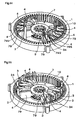
- the coils (as referred to Fig. 50) are inserted and arranged in the slots 10 which are formed in the inner circumference of the ring-shaped stator core 1.
- the coils here are omitted the coils (or the single-pole coils 8) so as to clarify the movements of the later-described insertion blades 3.
- the motor to be constructed by using the stator core 1 is the three-phase DC brushless motor.
- the stator core 1 in this embodiment is manufactured by laminating the ring-shaped electromagnetic steel sheets, and is provided in its inner circumference with the slots 10 for inserting the coils, as shown in Fig. 54 and Fig. 55.
- the stator core 1 is provided with the seventy two slots 10 so as to arrange the thirty six single-pole coils 8 in total. And, every twelve single-pole coils 8 bears each phase.
- two sets of coils having three single-pole coils 8 are prepared by the single take-up jig 7, and are simultaneously mounted in the stator core 1. By performing these works six times, all the single-pole coils 8 needed are mounted in the stator core 1.
- the take-up jig 7 is so arranged in the stator core 1 that coil retaining grooves 790, as formed between the winding frame 4 and the separate plate 79, in the take-up jig 7 may confront the slots 10 of the stator core 1, as shown in Fig. 54.
- the insertion blades 3 are inserted into the coil retaining grooves 790 of the take-up jig 7.
- the cutouts 420 formed in the frame body portion 42 of the winding frame 4 and the cutouts 430 and 440 (as referred to Fig. 39) formed in the upper and lower shaping blocks 43 and 44 provide provisional shaping grooves 795, into which the provisional shaping blades 34 are to be inserted.
- the insertion blades 3 are advanced in the coil retaining grooves 790 in the direction from the center to the outer circumference.
- the provisional shaping blades 34 are advanced in the provisional shaping grooves 795 in the direction from the center to the outer circumference.
- the single-pole coils 8 are pushed by the insertion blades 3 to move generally linearly from the coil retaining grooves 790 to the slots 10 of the stator core 1.
- the upper and lower coil end portions 802 (Fig. 50), as bulging from the stator core 1, in the single-pole coil 8 is subjected to a provisional shaping treatment, in which they are pushed and deformed outward by the provisional shaping blades 34.
- a second provisional shaping is executed by using the paired upper and lower formers 66 (as referred to Fig. 12) like those of Embodiment 1.
- the formers 66 have ring shapes, as described hereinbefore, and are provided, on their sides confronting the stator core 1, with the shaping faces 660 for profiling the coils into a desired shape.
- each former 66 is provided with cutouts 665 for preventing the insertion blades 3 and the provisional shaping blades 34 from interfering each other. And, the formers can be pushed onto the stator core 1 while the insertion blades 3 and the provisional shaping blades 34 being advanced.
- the paired upper and lower formers 66 thus constructed are individually advanced from their upper and lower positions and pushed onto the stator core 1.
- the second provisional shaping is performed such that the coil end portions 802, as bulging out from above and below the stator core 1, of the six single-pole coils 8 thus arranged in the stator core 1 fall down toward the stator core 1.
- the aforementioned coil forming apparatus is used to form two sets of coils having three single-pole coils 8, newly on the take-up jig 7.
- the movement of the coils from the take-up jig 7 directly to the stator core 1, the provisional shaping and the final second provisional shaping are performed six times in total, the thirty six single-pole coils 8 in total are mounted on the stator core 1.
- the shaping to be performed as the second provisional shaping by the formers is performed on all the thirty six single-pole coils 8 so that it becomes the proper shaping step of profiling the entire coil shape.
- the thirty six single-pole coils 8 in total are inserted and arranged in the stator core 1.
- a series of works are performed from the formation of the six single-pole coils to the second provisional shaping and are repeated six times.
- the efficiency can be enhanced by using a plurality of sets of take-up jigs 7.
- the steps can be rationalized by increasing the number of winding frames 4 in the take-up jig 7 from six to twelve and by moving the twelve single-pole coils 8 all at once to the stator core 1.
- this embodiment can also execute the so-called “linear insertion method", by which the coils are linearly moved, easily and stably.
- the coil retaining grooves 20, which are formed between the winding frames 4 and the separate plates 79, are parallel to each other for arranging the adjoining coil insertion portions 801 of the adjoining single-pole coils 8.
- the single-pole coils 8 can be linearly inserted without changing their postures into the slots 10. Therefore, it is not necessary to enlarge the vertical length of the coils more than necessary.
- the coils can be moved from the winding frames 4 having formed them, directly to the stator core 1, as described hereinbefore. Moreover, the coils need not be transferred, after formed, from the winding frames to another coil transfer device so that the coils can be highly efficiently mounted on the stator core. This is because the take-up jig 2 has the aforementioned excellent structure, as detailed hereinbefore.
- the coils can be inserted from the take-up jig 7 directly into the stator core 1 so that their movements can be easily executed even if the crossover lines connecting the single-pole coils 8 are short.
- a wedge inserting step is executed after completion of the coil inserting step of Embodiment 1.
- the slot 10 of the stator core 1 of this embodiment is provided, as shown in Fig. 57, with a slot open portion 102, which has its space portion constricted at its inner circumference end portion, and a general portion 101 which has a wider space than that of the slot open portion 102 on its outer circumference side.
- the wedge inserting step is performed to insert a wedge 901 into the slot 10 thereby to clog the inner circumference open portion in the slot 10.
- the wedge 901 used is provided, as shown in Fig. 56, with a wide portion 911 arranged in the general portion 101 of the slot 10, and a convex portion 912, which has a smaller width size than that of the wide portion 912, which is protruded from the wide portion 911 and which is arranged in the slot open portion 102.
- the stator core 1 in this embodiment has a ring shape and is provided at its inner circumference portion with a plurality of teeth 105, as shown in Fig. 57, to form the slot 10 inbetween.
- each tooth 105 extends radially from the outer circumference side to the inner circumference side and is provided at its leading end portion with protrusions 106 protruding in the circumferential directions.
- the space, at which those protrusions 106 confront each other, is the aforementioned slot open portion 102 in the slot 10, and the space on the outer circumference side is the aforementioned general portion 101.
- an insulating film 107 which is made of a synthetic resin having electrically insulating properties, as shown in the same Figure. Specifically, a film made of an LCP (Liquid Crystal Polymer) is formed in advance. In this embodiment, the insulating film 107 is set to have a thickness of about 300 microns.
- a sheet of electrically insulating aramid fibers of the prior art can also be applied to that insulating film 107.
- the wedge 901 is made of an LCP (Liquid Crystal Polymer) and is formed into an integral shape having the wide portion 911 and the convex portion 912.
- This convex portion 912 has a height size H1 slightly smaller than the radial size of the slot opening portion 102, i.e., the thickness size of the tooth 105.
- the width sizes W1 and W2 of the convex portion 912 and the wide portion 911 are so designed to correspond to the sizes of the space widths of the slot open portion 102 and the general portion 101 of the slot 10 as to establish a small clearance (although not shown) between the confronting teeth 105.
- This clearance is sized to be sufficiently smaller than both the size L (Fig. 57) of the protrusion of the inner wall face forming the slot open portion 102 in the stator core 1 from the inner wall face forming the general portion and the diameter D (Fig. 57) of the electric line forming the coil to be inserted and arranged in the slot 10.
- a small clearance is formed in the design between the wedge 901 and the tooth 105.
- the convex portion 912 may play the role to prevent the turning of the wedge 901, however, that clearance should be as small as possible. It is most desired that the wedge 901 contacts in face-to-face relation with the tooth 105 when it is mounted.
- the works to insert the wedges 901 into the slots 10 of the stator core 1 are done after all the single-pole coils 8 were inserted into the slots 10.
- a linear inserting method or a radial inserting method of moving the single-pole coils 8, as formed by winding the wire 88 in advance, generally linearly from the inner circumference side of the stator core 1 into the slots 10.
- the wedges 901 are inserted axially into the inner circumference openings of the slots 10.
- the wedges 901 are so inserted into the slots 10 that their convex portions 912 are positioned on the inner circumference side of the stator core 1 whereas the wide portions 911 are positioned on the outer circumference side, and such that those portions 912 and 911 correspond to the slot open portions 102 and the general portions 101 of the slots 10.
- the inner circumference openings of the slots 10 can be reliably clogged such that the wide portions 911 and the convex portions 912 of the wedges 901 are positioned in the general portions 101 and the slot open portions 102 of the slots 10, respectively.
- the wedge 901 of this embodiment has a shape composed of the wide portion 911 and the convex portion 912, as described hereinbefore, so that it is shaped to have a far superior rigidity than that of the wedge of the prior art, which is formed by bending a sheet-shaped material. Therefore, the wedge has such a strength as can stand sufficiently, even in case the wedge 901 is solely inserted after the single-pole coil 8 was inserted by the radial inserting method into the slot 10 of the stator core 1.
- the improved rigidity of the wedge 901 moreover, it is possible to make the width of the slot open portion wider than that of the prior art. Therefore, the radial inserting method can be more stably executed to rationalize the manufacturing process.
- the wide portion 911 and the convex portion 912 of the wedge 901 are arranged in the general portion 101 and the slot open portion 102 of the slot 10 of the stator core 1, respectively, as described hereinbefore.
- the convex portion 912 engages with the slot open portion 102 so that the wedge 901 can be prevented from turning and coming out of the slot open portion 102. Therefore, it is possible to keep the stable clogged state of the inner circumference opening 109 of the slot 10.
- an insertion apparatus 980 which can perform the coil insertion and the wedge insertion alternately.
- This insertion apparatus 980 includes: a coil inserting portion 981 for executing the radial insertion method by moving the single-pole coil 8 linearly from the inner circumference side of the stator core 1 to the outer circumference side; and a wedge inserting portion 990 for moving the wedge 901 in the axial direction.
- the axial direction and the radial direction in the following description will mean the axial direction and the radial direction of the motor of the case, in which the stator core 1 is arranged.
- the coil inserting portion 981 includes: a blade unit 982 disposed movably in the radial direction; and an insertion blade 983 erected axially from the blade unit 982. Moreover, the coil inserting portion 981 can move in the axial direction together with the wedge pusher 995 when it abuts against a later-described wedge pusher 995.
- a wedge magazine 993 having an arrangement hole 991 for arranging the wedge 901; and the wedge pusher 995 having a pushing pin portion 994 for pushing the wedge 901.
- This pushing pin portion 994 is extended in the axial direction from an arm portion 996 extended in the radial direction from the wedge pusher 995, and is constructed to move according to the axial movement of the wedge pusher 995.
- the wedge pusher 995 and the wedge magazine 993 can move synchronously in the axial direction till the wedge magazine 993 abuts against the stator core 1.
- the insertion blade 983 moved from the inner circumference side to the outer circumference side is brought into abutment against the coil 8 positioned on the inner circumference side of the stator core 1 and is moved to the outer circumference side.
- the coil 8 is inserted in a linear motion and arranged in the slot 10 of the stator core 1, as shown in Fig. 58 and Fig. 59.
- the wedge 901 is arranged in advance in the arrangement hole 991 of the wedge magazine 993, as shown in Fig. 58 and Fig. 60, and the wedge magazine 993 and the wedge pusher 995 are moved down synchronously in the axial direction.
- the wedge inserting portion 990 and the coil inserting portion 981 move synchronously as a whole in the axial direction, as shown in Fig. 62.
- the wedge magazine 993 After the wedge magazine 993 abutted against the stator core 1, as shown in Fig. 63, the wedge magazine 993 exclusively stops the downward movement, but the remaining portions continue the downward movements. As a result, the pushing pin portion 994 of the wedge pusher 995 penetrates into the arrangement hole 991 of the wedge magazine 993 thereby to push out the wedge 901 downward. As a result, the wedge 901 is inserted into the slot 10.
- the works to insert the wedge 901 can be reliably performed by using the insertion apparatus 980, after the works to insert the coil 8 by the radial insertion method.
- the wedge 901 of this embodiment has the highly rigid shape composed of the wide portion 911 and the convex portion 912, as described hereinbefore, so that it can be smoothly inserted while withstanding the pushing force of the pushing pin portion 72 sufficiently.
- This embodiment presents another example for inserting the two single-pole coils 8 simultaneously at the coin inserting step into the slots 10 of the stator core 1, as shown in Fig. 64 and Fig. 65.
- the coil inserting means to be used in this embodiment is constructed to move insertion blades 381 to 384, as can be inserted into the coil retaining grooves 20 of the magazine 2, by the push of a pair of surface and back pusher plates 39.
- the magazine 2 is provided, as in Embodiment 1, with the parallel coil retaining grooves 20, in which the adjoining coil insertion portions 801 (i.e., 801b and 801c in Fig. 64) of the adjoining single-pole coils 8 are to be inserted and arranged.
- the pusher plate 39 is disposed to have its advancing direction (i.e., a direction of arrow G) in parallel with the two parallel coil retaining grooves 20.
- the pusher plate 39 is provided, as shown in Fig. 64, with: a central flat portion 390 arranged perpendicularly of the advancing direction (i.e., the direction of arrow G); and slope portions 391 and 392 sloped to retract on the two sides from the central flat portion 391.
- the central flat portion 390 is constructed to push the insertion blades 382 and 383 to abut against the adjoining coil insertion portions 801b and 801c of the two adjoining single-pole coils 8, and the slope portions 391 and 392 on the two sides are constructed to push the insertion blades 381 and 384 to abut against the coil insertion portions 801a and 801d, respectively.
- the insertion blades 381 to 384 are provided with engaging pin portions 385 abutting against the pusher plate 39, so that they may individually protrude to the surface side and back side of the magazine 2.
- the two insertion blades 382 and 383 abutting against the central flat portion 390 of the pusher plate 39 are made slightly longer in the radial direction than the insertion blades 381 and 384 positioned on the two sides of the former, and are adjusted such that the leading ends of all the insertion blades 381 and 384 may be positioned on one arc around the center of the stator core 1.
- the angle of inclination ⁇ of the slope portions 391 and 392 of the pusher plate 39 is set at one half of the angle ⁇ made by the coil retaining groove 20 to insert the two coil insertion portions 801 (801a and 801b, or 801c and 801d) owned by each single-pole coil 8.
- ⁇ ⁇ /2.
- the two single-pole coils 8 When the two single-pole coils 8 are to be inserted into the slots 10 of the stator core 1 by using the magazine 2 and the coil inserting means thus constructed, the two single-pole coils 8 are retained by the magazine 2 acting as the coil retaining means, as shown in Fig. 64(a) and Fig. 65(a), and this magazine 2 is arranged in the stator core 1.
- the two single-pole coils 8 are naturally arranged such that the coil insertion portions 801 of each single-pole coil 8 may individually confront the inner circumference openings 109 of the slots 10 and may be generally parallel to the axial direction of the stator core 1.
- the coil inserting means is arranged, and the paired surface and back pusher plates 39 are advanced in the direction of arrow G.
- the four insertion blades 381 to 384 abutting against the pusher plates 39 are pushed by the pusher plates 39 to advance along the coil retaining grooves 20.
- all the insertion blades 381 to 384 then start movements simultaneously and continue the movements at the equal velocities.
- all the coil insertion portions 801a to 801d to abut against the individual insertion blades 381 to 384 start their movements simultaneously and continue the movements at the equal velocities so that they are simultaneously inserted into the slots 10 of the stator core 1 (Fig. 64(b) and Fig. 65(b)).
- the moving loci of the adjoining coil insertion portions 801b and 801c of the adjoining single-pole coils 8 before inserted into the slots 10, that is, while passing through the magazine 2 are parallel.
- the single-pole coils 8 can be moved not only generally linearly toward the stator core 1 but also such that the moving loci before the adjoining coil insertion portions 801b and 801c of the adjoining single-pole coils 8 are inserted into the slots 10 can be parallel.
- the two coil insertion portions 801 (i.e., 801a and 801b, or 801c and 801d) owned by each single-pole coil 8 can start their movements simultaneously and can move at the equal velocities
- the coil insertion portions 801 (i.e., 801b and 801c) owned by the adjoining single-pole coils 8 can start their movements simultaneously and can move at the equal velocities, so that all the coil insertion portions 801a to 801c can be simultaneously inserted into the slots 10 of the stator core 1.
- this embodiment presents an example, in which only the two single-pole coils 8 are simultaneously handled.
- three ormore single-pole coils 8 couldbe simultaneously handled and inserted into the slots 10.
Landscapes
- Engineering & Computer Science (AREA)
- Power Engineering (AREA)
- Manufacturing & Machinery (AREA)
- Manufacture Of Motors, Generators (AREA)
Abstract
Description
in that the coil insertion portions of the single-pole coils are inserted into the coil retaining grooves to retain the coils on the magazine;
in that the magazine is so arranged inside of the motor core that the coil retaining grooves of the magazine may confront the slots of the motor core; and
in that the motor manufacturing process comprises a coil inserting step of inserting the coil insertion portions of the single-pole coils into the slots, by bringing coil inserting means into abutment against all the single-pole coils on the magazine to advance the abutting portions in the direction from the center of the magazine to the outer circumference, thereby to move each single-pole coil substantially linearly toward the motor core such that it may leave the magazine and such that the two coil insertion portions owned by each single-pole coil may start their movements simultaneously and may take the equal velocities.
in that the coil insertion portions of the single-pole coils are inserted into the coil retaining grooves to retain the coils on the magazine;
in that the magazine is so arranged inside of the motor core that the coil retaining grooves of the magazine may confront the slots of the motor core; and
in that the motor manufacturing process comprises a coil inserting step of inserting the coil insertion portions of the single-pole coils into the slots, by bringing coil inserting means into abutment against all the single-pole coils on the magazine to advance the abutting portions in the direction from the center of the magazine to the outer circumference, thereby to move each single-pole coil substantially linearly toward the motor core such that it may leave the magazine and such that the two coil insertion portions owned by each single-pole coil may be simultaneously inserted into the slots.
Claims (37)
- A process for manufacturing a motor, which includes a ring-shaped motor core having slots formed in the inner circumference of said motor core and in which coils are inserted and arranged in the slots, characterized by comprising:the coil forming step of forming a coil including a plurality of single-pole coils having two coil insertion portions to be inserted into said slots and two coil end portions tying said coil insertion portions; andthe coil inserting step of inserting said coil insertion portions of said single-pole coils into said slots, by retaining said single-pole coils by coil retaining means at or after said coil forming step, by arranging said single-pole coils such that the coil insertion portions of each of said single-pole coils may confront the inner circumference openings of said slots and may be generally parallel to the axial direction of said motor core, by moving said each single-pole coil so generally linearly toward said motor core that it may leave said coil retaining means and that the moving locus before the adjoining coil insertion portions in the adjoining single-pole coils are inserted into said slots may be parallel or may approach the more from the inner circumference side to the outer circumference side, and by moving the two coil insertion portions owned by each single-pole coil, such that they may start their movements simultaneously and take the equal velocities.
- A process for manufacturing a motor, which includes a ring-shaped motor core having slots formed in the inner circumference of said motor core and in which coils are inserted and arranged in the slots, characterized by comprising:the coil forming step of forming a coil including a plurality of single-pole coils having two coil insertion portions to be inserted into said slots and two coil end portions tying said coil insertion portions; andthe coil inserting step of inserting said coil insertion portions of said single-pole coils into said slots, by retaining said single-pole coils by coil retaining means at or after said coil forming step, by arranging said single-pole coils such that the coil insertion portions of each of said single-pole coils may confront the inner circumference openings of said slots and may be generally parallel to the axial direction of said motor core, by moving said each single-pole coil so generally linearly toward said motor core that it may leave said coil retaining means and that the moving locus before the adjoining coil insertion portions in the adjoining single-pole coils are inserted into said slots may be parallel or may approach the more from the inner circumference side to the outer circumference side, and by moving the two coil insertion portions owned by each single-pole coil, such that they may be simultaneously inserted into said slots.
- A motor manufacturing process in Claim 1, characterized in that at said coil inserting step, each single-pole coil is moved so generally linearly toward said motor core that the moving locus of the winding center point of said each single-pole coil may be generally linear.
- A motor manufacturing process in Claim 1, characterized in that at said coil inserting step, said single-pole coils are so arranged on the inner circumference side of said motor core while being retained by said retaining means that said two coil insertion portions owned by said each single-pole coil may be individual positioned at an equal distance from said inner circumference openings of said slots.
- A motor manufacturing process in Claim 1, characterized in that at said coil inserting step, said two coil insertion portions owned by said each single-pole coil are moved such that they may start to advance simultaneously into said slots and may complete the advancements simultaneously.
- A motor manufacturing process in Claim 1, characterized in that at said coil inserting step, all said coil insertion portions owned by said single-pole coils start their movements simultaneously and take the equal velocities.
- A motor manufacturing process in Claim 1, characterized: in that said motor includes coil groups of a plurality of phases, each of which is composed of a plurality of said single-pole coils; and in that at said coil inserting step, all the single-pole coils belonging to one phase are arranged in said motor core so that their coil insertion portions of all said single-pole coils are started to move simultaneously and moved at the equal velocities.
- A motor manufacturing process in Claim 1, characterized in that the movements of said single-pole coil at said coil inserting step are done while the angle made between said coil insertion portions and the axial direction of said motor core being kept within 5 degrees.
- A motor manufacturing process in Claim 1, characterized in that at said coil inserting step, only said single-pole coil is inserted into said slot of said motor core.
- A motor manufacturing process in Claim 1, characterized in that at said coil inserting step, said single-pole coil is moved generally linearly toward said motor core, by applying insertion pressures individually at least to said two coil insertion portions of said single-pole coil.
- A motor manufacturing process in Claim 1, characterized in that at said coil inserting step, said single-pole coil is moved generally linearly toward said motor core, by applying insertion pressures individually at least to said two coil end portions of said single-pole coil.
- A motor manufacturing process in Claim 1, characterized in that at said coil inserting step, said single-pole coil is moved generally linearly toward said motor core, by applying insertion pressures individually to a plurality of positions, which are generally symmetric with respect to the winding center point of said each single-pole coil.
- A motor manufacturing process in Claim 1, characterized in that said motor is a distributed winding type motor including said ring-shaped motor core having said slots formed in its inner circumference and having coil groups of a plurality of phases, each of which is composed of said single-pole coils making one pole, in which the individual single-pole coils are individually inserted across said two slots and arranged in said motor core and in which the single-pole coils belonging to the coil groups of different phases overlap the coil end portions partially when they are mounted in said motor core.
- A motor manufacturing process in Claim 1, characterized in that said motor core is a stator core.
- A motor manufacturing process in Claim 1, characterized: in that said coil inserting step uses a magazine, which has such a shape as can be arranged on the inner side of the inner circumference of said motor core, which is provided in its outer circumference with a plurality of such coil retaining grooves at positions confronting said slots of said motor core as to arrange said coil insertion portions of said single-pole coil, and in which said coil retaining grooves for arranging the adjoining coil insertion portions in said adjoining single-pole coils are arranged either in parallel with each other or to approach each other from the inner circumference side to the outer circumference side;
in that said coil insertion portions of said single-pole coils are inserted into said coil retaining grooves to retain said coils on said magazine;
in that said magazine is so arranged inside of said motor core that said coil retaining grooves of said magazine may confront said slots of said motor core; and
in that all said single-pole coils are moved from said coil retaining grooves to said slots of said motor core by bringing coil inserting means into abutment against all said single-pole coils on said magazine thereby to advance the abutting portions in the direction from the center of said magazine to the outer circumference. - A process for manufacturing a motor, which includes a ring-shaped motor core having slots formed in the inner circumference of said motor core and in which coils are inserted and arranged in the slots, characterized by comprising:in that there is used a magazine, which has such a shape as can be arranged on the inner side of the inner circumference of said motor core, which is provided in its outer circumference with a plurality of such coil retaining grooves at positions confronting said slots of said motor core as to arrange said coil insertion portions of said single-pole coil, and in which said coil retaining grooves for arranging the adjoining coil insertion portions in said adjoining single-pole coils are arranged either in parallel with each other or to approach each other from the inner circumference side to the outer circumference side;the coil forming step of forming a coil including a plurality of single-pole coils having two coil insertion portions to be inserted into said slots and two coil end portions tying said coil insertion portions;
in that said coil insertion portions of said single-pole coils are inserted into said coil retaining grooves to retain said coils on said magazine;
in that said magazine is so arranged inside of said motor core that said coil retaining grooves of said magazine may confront said slots of said motor core; and
in that said motor manufacturing process comprises a coil inserting step of inserting said coil insertion portions of said single-pole coils into said slots, by bringing coil insertingmeans into abutment against all said single-pole coils on said magazine to advance the abutting portions in the direction from the center of said magazine to the outer circumference, thereby to move said each single-pole coil substantially linearly toward said motor core such that it may leave said magazine and such that the two coil insertion portions owned by each single-pole coil may start their movements simultaneously and may take the equal velocities. - A process for manufacturing a motor, which includes a ring-shaped motor core having slots formed in the inner circumference of said motor core and in which coils are inserted and arranged in the slots, characterized by comprising:in that there is used a magazine, which has such a shape as can be arranged on the inner side of the inner circumference of said motor core, which is provided in its outer circumference with a plurality of such coil retaining grooves at positions confronting said slots of said motor core as to arrange said coil insertion portions of said single-pole coil, and in which said coil retaining grooves for arranging the adjoining coil insertion portions in said adjoining single-pole coils are arranged either in parallel with each other or to approach each other from the inner circumference side to the outer circumference side;the coil forming step of forming a coil including a plurality of single-pole coils having two coil insertion portions to be inserted into said slots and two coil end portions tying said coil insertion portions;
in that said coil insertion portions of said single-pole coils are inserted into said coil retaining grooves to retain said coils on said magazine;
in that said magazine is so arranged inside of said motor core that said coil retaining grooves of said magazine may confront said slots of said motor core; and
in that said motor manufacturing process comprises a coil inserting step of inserting said coil insertion portions of said single-pole coils into said slots, by bringing coil inserting means into abutment against all said single-pole coils on said magazine to advance the abutting portions in the direction from the center of said magazine to the outer circumference, thereby to move said each single-pole coil substantially linearly toward said motor core such that it may leave said magazine and such that the two coil insertion portions owned by each single-pole coil may be simultaneously inserted into said slots. - A motor manufacturing process in Claim 15, characterized in that said coil inserting means includes insertion blades, which can be inserted into said coil retaining grooves of said magazine, so that said coil insertion portions are moved from said coil retaining grooves into said slots of said motor core by inserting said insertion blades into said coil retaining grooves to advance them from the center toward the outer circumference.
- A motor manufacturing process in Claim 15, characterized in that said coil inserting means includes a pair of split insertion blades, which can be inserted individually from the surface side and the back side of said magazine into said coil retaining grooves, so that said coil insertion portions are moved from said coil retaining grooves into said slots of said motor core by inserting said paired split insertion blades individually from the surface side and the back side of said magazine into said coil retaining grooves to bring them into abutment against said coil insertion portions and by advancing the abutting portions in the direction from the center to the outer circumference.
- A motor manufacturing process in Claim 15, characterized in that said coil inserting means includes a pair of split insertion hooks, which are divided on the surface side and the back side of said magazine, so that said coil insertion portions are moved from said coil retaining grooves into said slots of said motor core by bringing said paired split insertion hooks individually into abutment against said coil end portions protruding to the surface side and the back side of said magazine to advance them in the direction from the center of saidmagazine to the outer circumference.
- A motor manufacturing process in Claim 15, characterized in that simultaneously with or after the movement of said coil insertion portions from said coil retaining grooves to said slots, a provisional shaping step of pushing and deforming said coil end portions is performed by advancing provisional shaping means arranged between said adjoining coil retaining grooves in the direction from the center of said magazine to the outer circumference.
- A motor manufacturing process in Claim 21, characterized in that said magazine is provided with provisional shaping grooves in juxtaposition to said coil retaining grooves, and in that provisional shaping blades capable of being inserted into said provisional shaping grooves are used as said provisional shaping means, so that said provisional shaping step is performed by inserting said provisional shaping blades into said provisional shaping grooves to advance them in the direction from the center to the outer circumference.
- A motor manufacturing process in Claim 21, characterized in that said provisional shaping means includes a pair of split provisional shaping blades split on the surface side and the back side of said magazine, so that said provisional shaping step is performed by advancing said paired split provisional shaping blades on the surface side and the back side of said magazine in the direction from the center of said magazine to the outer circumference.
- A motor manufacturing process in Claim 23, characterized in that said coil inserting means includes a pair of split provisional shaping blades split on the surface side and the back side of said magazine, and in that said split insertion blades and said split provisional shaping blades are associated with each other.
- A motor manufacturing process in Claim 21, characterized in that after said coil inserting step and said provisional shaping step were repeated a plurality of times, a proper shaping step of shaping said coil end portions is performed by pushing a former having shaping faces for profiling said coil end portions into a desired shape, onto said motor core.
- A motor manufacturing process in Claim 25, characterized in that said formers are provided with cutouts for preventing the interference between said coil inserting means and said provisional shaping means, and in that said formers are pushed onto said motor core while said coil inserting means and said provisional shaping means being kept in the advanced state.
- A motor manufacturing process in Claim 1, characterized in that said motor is a three-phase DC brushless motor, and in that at said coil inserting step, the single-pole coils of one phase are simultaneously inserted into said slots of said motor core.
- A motor manufacturing process in Claim 15, characterized: in that said coil forming step uses a take-up jig, which includes a base holder and a plurality of winding frames arranged radially on the outer circumference of said base holder, in which said winding frames are arranged to move back and forth with respect to said base holder, and in which said coil retaining grooves for arranging the adjoining coil insertion portions in said adjoining single-pole coils are arranged between the adjoining winding frames either in parallel with each other or such that they approach more from the inner circumference side to the outer circumference side;
in that said motor manufacturing process comprises:in that said winding frame protruding step, said winding step and said winding frame retracting step are sequentially repeated on the adjoining winding frames and are performed at said winding step by reversing the turning directions of said take-up jig sequentially; anda winding frame protruding step of advancing one of said winding frames to protrude more than the remaining winding frames;a winding step of winding an electric line on said protruded winding frame to form the single-pole coil, by feeding said protruded winding frame in one direction with the electric line and by turning said take-up jig as a whole on the axis of said winding frame; anda winding frame retracting step of retracting said winding frame having said single-pole coil formed;
in that at said coil inserting step, said take-up jig is used as said magazine so said take-up jig retaining said coil is arranged inside of said motor core and so that said each single-pole coil is moved from said winding frame directly to said slots of said motor core. - A motor manufacturing process in Claim 28, characterized in that said base holder in said take-up jig exhibits a disc shape, and in that said winding frames are arranged to move back and forth along the axes extending radially from the center point of said base holder.
- A motor manufacturing process in Claim 28, characterized in that said each winding frame in said take-up jig has a sector shape made wider along said axis.
- A motor manufacturing process in Claim 28, characterized in that said each winding frame in said take-up jig is removably provided with shaping blocks for profiling the shape of the single-pole coil to be wound.
- A motor manufacturing process in Claim 28, characterized in that said take-up jig has such a contour formed of the leading ends of said winding frames while all said winding frames being retracted as is circular around the center point of said base holder.
- A motor manufacturing process in Claim 28, characterized in that separate plates extended from the outer circumference of said base holder are so arranged on the two sides of said each winding frame that a predetermined spacing is retained between said separate plates and said winding frame.
- A motor manufacturing process in Claim 1, characterized: in that said slot of said motor core includes: a slot open portion constricted in a space portion at its inner circumference end portion; and a general portion formed on the outer circumference side of said slot open portion and made larger in the space width than said slot open portion; and
in that after said coil inserting step, a wedge inserting step is performed to insert the wedge in the axial direction of said motor core into said slot so that the inner circumference opening in said slot may be clogged. - A motor manufacturing process in Claim 34, characterized in that said wedge includes a wide portion arranged in said general portion of said slot, and a convex portion, which has a smaller width size than that of said wide portion, which is protruded from said wide portion and which is arranged in said slot open portion.
- A motor manufacturing process in Claim 35, characterized in that said wedge is molded of a synthetic resin integrally with said wide portion and said convex portion.
- A motor manufacturing process in Claim 34, characterized: in that at said coil inserting step, insertion blades capable of penetrating into said slots are used to push and guide said coil insertion portions into said slots, and penetrate by themselves into said slots; and
in that at said wedge inserting step, said insertion blades and said wedge are moved in association with each other in the axial direction of saidmotor core and are interchanged to insert said wedge into said slot.
Applications Claiming Priority (5)
| Application Number | Priority Date | Filing Date | Title |
|---|---|---|---|
| PCT/JP2002/007749 WO2003012961A1 (en) | 2001-07-31 | 2002-07-30 | Motor production method and coil insertion apparatus |
| WOPCT/JP02/07749 | 2002-07-30 | ||
| JP2003023222 | 2003-01-31 | ||
| JP2003023222A JP4259127B2 (en) | 2002-07-30 | 2003-01-31 | Manufacturing method of motor |
| PCT/JP2003/009699 WO2004012324A1 (en) | 2002-07-30 | 2003-07-30 | Motor manufacturing method |
Publications (3)
| Publication Number | Publication Date |
|---|---|
| EP1526630A1 true EP1526630A1 (en) | 2005-04-27 |
| EP1526630A4 EP1526630A4 (en) | 2006-10-25 |
| EP1526630B1 EP1526630B1 (en) | 2012-08-29 |
Family
ID=31189660
Family Applications (1)
| Application Number | Title | Priority Date | Filing Date |
|---|---|---|---|
| EP03771441A Expired - Lifetime EP1526630B1 (en) | 2002-07-30 | 2003-07-30 | Motor manufacturing method |
Country Status (5)
| Country | Link |
|---|---|
| EP (1) | EP1526630B1 (en) |
| JP (1) | JP4259127B2 (en) |
| KR (1) | KR100965500B1 (en) |
| CN (1) | CN100471011C (en) |
| WO (1) | WO2004012324A1 (en) |
Cited By (4)
| Publication number | Priority date | Publication date | Assignee | Title |
|---|---|---|---|---|
| WO2007080340A1 (en) * | 2006-01-16 | 2007-07-19 | Valeo Equipements Electriques Moteur | Device for the radial transfer of a stator coil |
| CN101667766B (en) * | 2009-09-22 | 2011-06-22 | 天津市天发重型水电设备制造有限公司 | Method for gradually inserting coil of loop-type coils of high-voltage motor |
| CN107910994A (en) * | 2017-12-14 | 2018-04-13 | 中际旭创股份有限公司 | Wave-winding machine rewinds wire clamp clamping device |
| US11705792B2 (en) | 2019-05-09 | 2023-07-18 | Nittoku Co., Ltd. | Coil insertion device and coil insertion method |
Families Citing this family (16)
| Publication number | Priority date | Publication date | Assignee | Title |
|---|---|---|---|---|
| CN1767319B (en) * | 2004-10-29 | 2010-09-29 | 株式会社日立制作所 | Rotating electric machine and manufacturing method thereof |
| US7712697B1 (en) * | 2009-06-05 | 2010-05-11 | Remy Technologies, L.L.C. | Core winding apparatus and method of winding a core |
| US20100133945A1 (en) * | 2009-06-05 | 2010-06-03 | Remy International Inc. | Segmented stator core winding apparatus and method of winding a segmented stator core |
| US9118225B2 (en) * | 2012-08-24 | 2015-08-25 | Caterpillar Inc. | Coil with twisted wires and stator assembly of a rotary electric machine |
| JP6203785B2 (en) | 2015-06-25 | 2017-09-27 | ファナック株式会社 | Electric motor having 8-shaped connecting coil and manufacturing method thereof |
| JP6583041B2 (en) * | 2016-02-18 | 2019-10-02 | アイシン・エィ・ダブリュ株式会社 | Stator assembly method |
| JP6591658B2 (en) * | 2016-03-22 | 2019-10-16 | 本田技研工業株式会社 | Alignment method and alignment apparatus |
| CN106787475B (en) * | 2016-12-25 | 2023-05-05 | 中船重工电机科技股份有限公司 | Generator rotor tower coil shaping device |
| JP2018107990A (en) * | 2016-12-28 | 2018-07-05 | 日本電産株式会社 | Support member mounting method and motor |
| CN108988518B (en) * | 2018-08-01 | 2023-08-25 | 台州环洋机电有限公司 | Multistage motor stator combined structure and manufacturing process thereof |
| CN111786520B (en) * | 2020-07-10 | 2023-03-24 | 陕西航空电气有限责任公司 | Generator stator concentrated winding wire inserting tool and wire inserting method thereof |
| JP7487676B2 (en) * | 2021-01-29 | 2024-05-21 | ニデック株式会社 | Coil Insertion Device |
| DE102021122587B3 (en) * | 2021-09-01 | 2022-12-01 | Gehring Technologies Gmbh + Co. Kg | Device and method for positioning a plurality of conductor pieces for equipping a stator core with conductor pieces |
| KR20240043949A (en) | 2022-09-28 | 2024-04-04 | 현대자동차주식회사 | Stator for AFPM motor and manufacturing method thereof |
| CN115833507B (en) * | 2022-11-30 | 2026-04-17 | 浙江鸿运实业有限公司 | An automatic winding fixture for starter rotors |
| WO2025173669A1 (en) * | 2024-02-15 | 2025-08-21 | 日本発條株式会社 | Loading device and method for segment coil |
Family Cites Families (14)
| Publication number | Priority date | Publication date | Assignee | Title |
|---|---|---|---|---|
| US1538187A (en) * | 1923-03-27 | 1925-05-19 | Domestic Electric Company | Method and apparatus for placing windings in motor stators |
| US2873514A (en) * | 1954-12-31 | 1959-02-17 | Smith Corp A O | Cam-actuated coil inserter |
| US3193913A (en) * | 1960-09-02 | 1965-07-13 | Harry W Moore | Coil transferring machine |
| JPS51138803A (en) * | 1975-05-28 | 1976-11-30 | Hitachi Ltd | Inserting device of coil into electric motor |
| JPS5594567A (en) * | 1979-01-10 | 1980-07-18 | Nippon Denso Co Ltd | Winding method for winding unit of rotary machine |
| JPS5619363A (en) * | 1979-07-19 | 1981-02-24 | Matsushita Electric Ind Co Ltd | Inserting method for coil winding and inserting device for coil winding |
| JPS59103549A (en) * | 1982-12-01 | 1984-06-15 | Hitachi Ltd | coil insertion device |
| JPS631349A (en) * | 1986-06-20 | 1988-01-06 | Yaskawa Electric Mfg Co Ltd | Winding apparatus |
| US4908541A (en) * | 1986-08-28 | 1990-03-13 | Mitsuba Electric Mfg., Co., Ltd. | Air-cooled layered coil vehicle AC generator stator |
| JPH0348485A (en) * | 1989-07-17 | 1991-03-01 | Yazaki Corp | Reinforcing method for conductive property of polymer type copper paste circuit board |
| US5060364A (en) * | 1990-11-01 | 1991-10-29 | Advanced Machine & Tool Corporation | Wedge inserter with intermediate wedge support |
| JPH099588A (en) * | 1995-06-21 | 1997-01-10 | Toyota Motor Corp | Motor stator manufacturing method |
| JP3791426B2 (en) * | 2001-02-20 | 2006-06-28 | 日産自動車株式会社 | Coil insertion method and apparatus |
| CN1465128B (en) * | 2001-07-31 | 2010-04-21 | 爱信艾达株式会社 | Method for manufacturing motor |
-
2003
- 2003-01-31 JP JP2003023222A patent/JP4259127B2/en not_active Expired - Fee Related
- 2003-07-30 CN CNB038016842A patent/CN100471011C/en not_active Expired - Fee Related
- 2003-07-30 WO PCT/JP2003/009699 patent/WO2004012324A1/en not_active Ceased
- 2003-07-30 KR KR1020057001603A patent/KR100965500B1/en not_active Expired - Fee Related
- 2003-07-30 EP EP03771441A patent/EP1526630B1/en not_active Expired - Lifetime
Cited By (6)
| Publication number | Priority date | Publication date | Assignee | Title |
|---|---|---|---|---|
| WO2007080340A1 (en) * | 2006-01-16 | 2007-07-19 | Valeo Equipements Electriques Moteur | Device for the radial transfer of a stator coil |
| FR2896352A1 (en) * | 2006-01-16 | 2007-07-20 | Valeo Equip Electr Moteur | DEVICE FOR RADIALLY TRANSFERRING A STATOR WINDING |
| CN101667766B (en) * | 2009-09-22 | 2011-06-22 | 天津市天发重型水电设备制造有限公司 | Method for gradually inserting coil of loop-type coils of high-voltage motor |
| CN107910994A (en) * | 2017-12-14 | 2018-04-13 | 中际旭创股份有限公司 | Wave-winding machine rewinds wire clamp clamping device |
| CN107910994B (en) * | 2017-12-14 | 2023-10-27 | 山东中际智能装备有限公司 | Reverse winding wire clamp clamping device of waveform winding machine |
| US11705792B2 (en) | 2019-05-09 | 2023-07-18 | Nittoku Co., Ltd. | Coil insertion device and coil insertion method |
Also Published As
| Publication number | Publication date |
|---|---|
| JP2004064990A (en) | 2004-02-26 |
| EP1526630A4 (en) | 2006-10-25 |
| JP4259127B2 (en) | 2009-04-30 |
| EP1526630B1 (en) | 2012-08-29 |
| WO2004012324A1 (en) | 2004-02-05 |
| CN1596498A (en) | 2005-03-16 |
| CN100471011C (en) | 2009-03-18 |
| KR100965500B1 (en) | 2010-06-25 |
| KR20050113160A (en) | 2005-12-01 |
Similar Documents
| Publication | Publication Date | Title |
|---|---|---|
| US7275299B2 (en) | Motor manufacturing process | |
| EP1526630B1 (en) | Motor manufacturing method | |
| US8302286B2 (en) | Method for manufacturing a stator winding | |
| US7311284B2 (en) | Coil forming method and coil forming device | |
| US20040098856A1 (en) | Motor production method and coil insertion apparatus | |
| JP5647735B2 (en) | Stator manufacturing method and stator manufacturing apparatus | |
| US8936211B2 (en) | Method of manufacturing stator and coil insertion apparatus | |
| US12390852B2 (en) | Method and apparatus for production of a multiphase electromagnetic mat for forming current carrying components of a power conversion system | |
| JP2017046373A (en) | Method of inserting coil into slot, and coil insertion device | |
| KR101935622B1 (en) | Coil winding/setting method, coil inserting method, and coil winding/setting apparatus | |
| US20090145995A1 (en) | Winding device for a field coil, processing equipment and electric machine | |
| JP2005080488A (en) | Rotating electrical machine stator coil end expansion molding method and apparatus |
Legal Events
| Date | Code | Title | Description |
|---|---|---|---|
| PUAI | Public reference made under article 153(3) epc to a published international application that has entered the european phase |
Free format text: ORIGINAL CODE: 0009012 |
|
| 17P | Request for examination filed |
Effective date: 20050201 |
|
| AK | Designated contracting states |
Kind code of ref document: A1 Designated state(s): AT BE BG CH CY CZ DE DK EE ES FI FR GB GR HU IE IT LI LU MC NL PT RO SE SI SK TR |
|
| RBV | Designated contracting states (corrected) |
Designated state(s): DE FR GB |
|
| A4 | Supplementary search report drawn up and despatched |
Effective date: 20060922 |
|
| 17Q | First examination report despatched |
Effective date: 20070122 |
|
| REG | Reference to a national code |
Ref country code: DE Ref legal event code: R079 Ref document number: 60341967 Country of ref document: DE Free format text: PREVIOUS MAIN CLASS: H02K0015060000 Ipc: H02K0015040000 |
|
| GRAP | Despatch of communication of intention to grant a patent |
Free format text: ORIGINAL CODE: EPIDOSNIGR1 |
|
| RIC1 | Information provided on ipc code assigned before grant |
Ipc: H02K 15/06 20060101ALN20120126BHEP Ipc: H02K 15/04 20060101AFI20120126BHEP Ipc: H02K 15/00 20060101ALI20120126BHEP |
|
| RIC1 | Information provided on ipc code assigned before grant |
Ipc: H02K 15/06 20060101ALN20120227BHEP Ipc: H02K 15/04 20060101AFI20120227BHEP Ipc: H02K 15/00 20060101ALI20120227BHEP |
|
| RIN1 | Information on inventor provided before grant (corrected) |
Inventor name: YAMAGUCHI, TSUYOSHI Inventor name: KUROYANAGI, TOORU Inventor name: KIDO, TAKAHIRO Inventor name: HASHIMOTO, SHINGO |
|
| GRAS | Grant fee paid |
Free format text: ORIGINAL CODE: EPIDOSNIGR3 |
|
| GRAA | (expected) grant |
Free format text: ORIGINAL CODE: 0009210 |
|
| AK | Designated contracting states |
Kind code of ref document: B1 Designated state(s): DE FR GB |
|
| REG | Reference to a national code |
Ref country code: GB Ref legal event code: FG4D |
|
| REG | Reference to a national code |
Ref country code: DE Ref legal event code: R096 Ref document number: 60341967 Country of ref document: DE Effective date: 20121025 |
|
| PLBE | No opposition filed within time limit |
Free format text: ORIGINAL CODE: 0009261 |
|
| STAA | Information on the status of an ep patent application or granted ep patent |
Free format text: STATUS: NO OPPOSITION FILED WITHIN TIME LIMIT |
|
| 26N | No opposition filed |
Effective date: 20130530 |
|
| REG | Reference to a national code |
Ref country code: DE Ref legal event code: R097 Ref document number: 60341967 Country of ref document: DE Effective date: 20130530 |
|
| REG | Reference to a national code |
Ref country code: FR Ref legal event code: PLFP Year of fee payment: 13 |
|
| PGFP | Annual fee paid to national office [announced via postgrant information from national office to epo] |
Ref country code: GB Payment date: 20150729 Year of fee payment: 13 Ref country code: DE Payment date: 20150722 Year of fee payment: 13 |
|
| PGFP | Annual fee paid to national office [announced via postgrant information from national office to epo] |
Ref country code: FR Payment date: 20150629 Year of fee payment: 13 |
|
| REG | Reference to a national code |
Ref country code: DE Ref legal event code: R119 Ref document number: 60341967 Country of ref document: DE |
|
| GBPC | Gb: european patent ceased through non-payment of renewal fee |
Effective date: 20160730 |
|
| PG25 | Lapsed in a contracting state [announced via postgrant information from national office to epo] |
Ref country code: DE Free format text: LAPSE BECAUSE OF NON-PAYMENT OF DUE FEES Effective date: 20170201 Ref country code: FR Free format text: LAPSE BECAUSE OF NON-PAYMENT OF DUE FEES Effective date: 20160801 |
|
| REG | Reference to a national code |
Ref country code: FR Ref legal event code: ST Effective date: 20170331 |
|
| PG25 | Lapsed in a contracting state [announced via postgrant information from national office to epo] |
Ref country code: GB Free format text: LAPSE BECAUSE OF NON-PAYMENT OF DUE FEES Effective date: 20160730 |