EP1526332A2 - Fuel injection nozzle - Google Patents
Fuel injection nozzle Download PDFInfo
- Publication number
- EP1526332A2 EP1526332A2 EP20040023823 EP04023823A EP1526332A2 EP 1526332 A2 EP1526332 A2 EP 1526332A2 EP 20040023823 EP20040023823 EP 20040023823 EP 04023823 A EP04023823 A EP 04023823A EP 1526332 A2 EP1526332 A2 EP 1526332A2
- Authority
- EP
- European Patent Office
- Prior art keywords
- fuel
- injection nozzle
- fuel injection
- air
- nozzle according
- Prior art date
- Legal status (The legal status is an assumption and is not a legal conclusion. Google has not performed a legal analysis and makes no representation as to the accuracy of the status listed.)
- Withdrawn
Links
- 239000000446 fuel Substances 0.000 title claims abstract description 132
- 238000002347 injection Methods 0.000 title claims abstract description 41
- 239000007924 injection Substances 0.000 title claims abstract description 41
- 230000001154 acute effect Effects 0.000 claims abstract description 4
- 239000000203 mixture Substances 0.000 description 16
- MWUXSHHQAYIFBG-UHFFFAOYSA-N Nitric oxide Chemical compound O=[N] MWUXSHHQAYIFBG-UHFFFAOYSA-N 0.000 description 12
- 238000002485 combustion reaction Methods 0.000 description 10
- 239000007789 gas Substances 0.000 description 8
- 230000035515 penetration Effects 0.000 description 6
- 238000002156 mixing Methods 0.000 description 5
- 230000001133 acceleration Effects 0.000 description 4
- 239000006199 nebulizer Substances 0.000 description 4
- 230000015572 biosynthetic process Effects 0.000 description 3
- 238000007493 shaping process Methods 0.000 description 3
- 238000010276 construction Methods 0.000 description 2
- 239000007788 liquid Substances 0.000 description 2
- 238000002360 preparation method Methods 0.000 description 2
- 241000446313 Lamella Species 0.000 description 1
- 238000005352 clarification Methods 0.000 description 1
- 238000011109 contamination Methods 0.000 description 1
- 238000000354 decomposition reaction Methods 0.000 description 1
- 230000007423 decrease Effects 0.000 description 1
- 230000001419 dependent effect Effects 0.000 description 1
- 239000003344 environmental pollutant Substances 0.000 description 1
- 230000002349 favourable effect Effects 0.000 description 1
- 239000008240 homogeneous mixture Substances 0.000 description 1
- 230000001771 impaired effect Effects 0.000 description 1
- 230000007246 mechanism Effects 0.000 description 1
- 231100000719 pollutant Toxicity 0.000 description 1
- 239000000243 solution Substances 0.000 description 1
- 239000007921 spray Substances 0.000 description 1
- 230000006641 stabilisation Effects 0.000 description 1
- 238000011105 stabilization Methods 0.000 description 1
Images


Classifications
-
- F—MECHANICAL ENGINEERING; LIGHTING; HEATING; WEAPONS; BLASTING
- F23—COMBUSTION APPARATUS; COMBUSTION PROCESSES
- F23D—BURNERS
- F23D11/00—Burners using a direct spraying action of liquid droplets or vaporised liquid into the combustion space
- F23D11/10—Burners using a direct spraying action of liquid droplets or vaporised liquid into the combustion space the spraying being induced by a gaseous medium, e.g. water vapour
- F23D11/106—Burners using a direct spraying action of liquid droplets or vaporised liquid into the combustion space the spraying being induced by a gaseous medium, e.g. water vapour medium and fuel meeting at the burner outlet
- F23D11/107—Burners using a direct spraying action of liquid droplets or vaporised liquid into the combustion space the spraying being induced by a gaseous medium, e.g. water vapour medium and fuel meeting at the burner outlet at least one of both being subjected to a swirling motion
-
- F—MECHANICAL ENGINEERING; LIGHTING; HEATING; WEAPONS; BLASTING
- F23—COMBUSTION APPARATUS; COMBUSTION PROCESSES
- F23R—GENERATING COMBUSTION PRODUCTS OF HIGH PRESSURE OR HIGH VELOCITY, e.g. GAS-TURBINE COMBUSTION CHAMBERS
- F23R3/00—Continuous combustion chambers using liquid or gaseous fuel
- F23R3/28—Continuous combustion chambers using liquid or gaseous fuel characterised by the fuel supply
-
- F—MECHANICAL ENGINEERING; LIGHTING; HEATING; WEAPONS; BLASTING
- F23—COMBUSTION APPARATUS; COMBUSTION PROCESSES
- F23D—BURNERS
- F23D2900/00—Special features of, or arrangements for burners using fluid fuels or solid fuels suspended in a carrier gas
- F23D2900/11101—Pulverising gas flow impinging on fuel from pre-filming surface, e.g. lip atomizers
Definitions
- the invention relates to a fuel injector according to the features of the preamble of the main claim.
- the invention relates to a fuel injector for a gas turbine combustor with a film former, on which a plurality of fuel openings formed are.
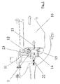
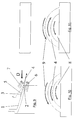
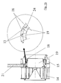
- Fig. 1 shows a schematic side sectional view of a Combustion chamber 10 with associated fuel injection.
- a schematic view of the supply of air to a inner swirler 14 and an outer swirler 15 are shown.
- the fuel-air mixture 13 flows in a known manner in the combustion chamber 10 a.
- the stabilization of the combustion takes place almost exclusively with air swirl, which is a recirculation of partially combusted gases allows.
- the fuel is often centrally through a nozzle introduced, which mounted on the center axis of the atomizer is.
- the fuel is often with considerable Overpressure injected into the air flow enough to Penetration to achieve and as much air with fuel to be able to premix.
- These pressure atomizers have to one the function to directly atomize fuel.
- the fuel gets through the air on a nebulizer lip accelerated and at the downstream end of this lip Torn into small drops and mixed with the air.
- a another way of putting the fuel on this nebulizer lip to raise, consists with a so-called film depositor, wherein Fuel is distributed as uniformly as possible in a film.
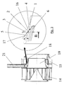
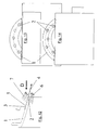
- FIG. 2 Another way of keeping the fuel as intense as possible to mix with a large part of the air, consists in one decentralized injection (Fig. 2) from the outer boundary a flow channel formed by a film feeder 1, which the majority of the air leads. This can be from a nebulizer lip or else from the outer nozzle contour.
- This injection is characterized in that, different as with a film-maker, the fuel is one defined Penetration into the main air flow should learn.
- the fuel nozzles are often through one in the radial direction very uneven velocity and mass flow distribution characterized. Due to the swirl of the air, which needed to stabilize the subsequent combustion is, the local air mass flow in the area of the radial outer boundary wall largest. Is the fuel out a few openings introduced into the flow, on the one hand the homogeneity of the fuel in the air in the circumferential direction impaired, on the other hand, the fuel can be very penetrate deeply into the flow and thus unintentionally in Regions mix and vaporize where not sufficient Air is available. This can also be done with a decentralized Injection occur.
- the invention is based on the object, a fuel injector to create the type mentioned, which at simple construction and reliable operation a uniform Mixing of fuel and air ensured.
- This essentially Parallel arrangement can also be up to a range of the absolute Diverge in parallelism through an acute angle is marked. Purely for structural reasons, it is not always possible, the fuel injection completely parallel perform. According to the invention, it is important that the fuel injection has a high axial component and the fuel thus not injected radially.
- the fuel openings may be on a radially inner wall
- the filmmaker can be created, but you can also at a Leave the rear edge of the same.
- the film-maker or the area of injection of the fuel is preferably arranged between two swirlers.
- the fuel openings in addition are inclined in the twisting direction of the air, i. an additional Have circumferential component. This can be in the same direction or be formed in the counter-twist. Furthermore, it is according to the invention possible, the fuel ports single row, multi-row, to arrange flush with each other or staggered to each other.
- the film-maker can also be designed like a lamella be to even better mixing of the air-fuel mixture to reach.
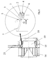
- Fig. 3 shows a simplified representation of a section by the film applicator 1 according to the invention, wherein fuel openings 2, in particular fuel bores 3, shown are whose center axes 5 by an angle ⁇ to the main flow direction 6 (wall-near flow direction in the inner swirl duct) are inclined.
- the reference numeral 16 shows a hired wall element of Filmlegers 1
- the reference numeral 17 shows an aerodynamic adapted film layer surface.
- the reference numeral 21 is a fuel line shown.
- the invention avoids the unwanted intrusion of the liquid Fuel in areas with low flow rates and the associated uneven fuel-air mixture.
- a proposed embodiment is shown in FIG. 3 shown.
- the fuel is here at a film layer not radially inward, i. with a high radial component the exit velocity of the fuel into an inner Injected swirl channel. Rather, in the proposed concept a high axial component of the exit velocity the fuel is present and the fuel is approaching parallel to the main flow direction of the inner swirl duct brought in.
- Fig. 3 are schematically the fuel ports as well as the Ausdüsung of the fuel shown.
- the fuel is initially through the openings shown over a hired against the air flow direction Angle ⁇ injected, which is formed as an acute angle.
- Angle ⁇ injected which is formed as an acute angle.
- the fuel openings in the circumferential direction arranged in the same or counter-rotation to the air flow be.
- the shape of the openings can also be different be executed, i. round, elliptical, etc.
- Construction will be the development of a fuel film in a radially very limited flow layer guaranteed. At the trailing edge of the filmmaker rips the Fuel film decreases and is accelerated by the presence of and twisted air from the outer and inner Flow channel homogeneously mixed.
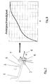
- FIG. 4 Another embodiment of the invention provides the injection of the fuel at the trailing edge of a flow divider between two swirlers before (Fig. 4).
- the speed maxima the accelerated and twisted in the swirl generator Air is near the wall of the formed flow divider, i.e. in the outer flow of the boundary layer both sides of the flow divider.
- Figs. 7 and 8 show the axial acceleration of the flow in the wake of the trailing edge of the flow divider, where x is the axial distance from the trailing edge of the flow divider is.
- FIG. 15 is to schematically illustrated a variant of the filmmaker.
- a Aero engine is aimed at different mass air flows To bring together loss as possible to a total flow.
- the mixture should be in the proposed burner concept however, to an improved mixture formation by a three-dimensional mixing of a twisted air stream with a partially premixed with air fuel flow to lead.
- the twisted air from the outer channel periodically penetrates into the inner channel through the shaping one. With an injection of the fuel in the inner or outer Spinal canal develops as the residence time increases downstream of the coater a fuel-air mixture. This Mixture may also be due to the shaping in the inner Penetrate swirl channel.
- the film layer can thus produce a flow layer be in a very intense mixture of the fuel-air mixture from the inner canal and pure air mixing can be done from the outer swirl duct or vice versa.
- the uniform temperature field with low absolute temperatures and low nitrogen oxide levels.
- Another feature the embodiment shown in Fig. 15 can also be a Flange-adapted spiral geometry of the lamellar film layer be in which the lamellar geometry correspondingly effective adapted to the air swirl near the wall of the filmmaker.
- the advantage of the invention is thus a practice-relevant solution the problem of premixing fuel homogeneously with air and this with as few, relatively large fuel ports a defined and not too large penetration depth of the Fuel into the air flow to achieve.
- Overall goal is the reduction of nitrogen oxide ejection of the gas turbine combustor with a robust and technically feasible fuel injection configuration.
Landscapes
- Engineering & Computer Science (AREA)
- Chemical & Material Sciences (AREA)
- Combustion & Propulsion (AREA)
- Mechanical Engineering (AREA)
- General Engineering & Computer Science (AREA)
- Spray-Type Burners (AREA)
- Nozzles For Spraying Of Liquid Fuel (AREA)
Abstract
Description
Die Erfindung bezieht sich auf eine Kraftstoffeinspritzdüse nach den Merkmalen des Oberbegriffs des Hauptanspruchs.The invention relates to a fuel injector according to the features of the preamble of the main claim.
Im Einzelnen bezieht sich die Erfindung auf eine Kraftstoffeinspritzdüse für eine Gasturbinenbrennkammer mit einem Filmleger, an welchem mehrere Kraftstofföffnungen ausgebildet sind.More particularly, the invention relates to a fuel injector for a gas turbine combustor with a film former, on which a plurality of fuel openings formed are.
Die Gemischaufbereitung von Kraftstoff und Luft in Gasturbinenbrennkammern erfolgt auf sehr unterschiedliche Weise und lässt sich grundsätzlich bezüglich ihrer Anwendung für stationäre Gasturbinen oder Fluggasturbinen und somit hinsichtlich der unterschiedlichen Anforderungen unterscheiden. Zur Reduzierung des Schadstoffausstoßes vornehmlich der Stickoxidemissionen, muss jedoch generell der Kraftstoff mit möglichst viel Luft vorgemischt werden, um einen mageren durch Luftüberschuss gekennzeichneten Verbrennungszustand einzustellen. Diese Mischung ist problematisch, da sie durch die Verbrennung stabilisierende Mechanismen beeinträchtigen kann.Mixture preparation of fuel and air in gas turbine combustion chambers takes place in very different ways and leaves basically with regard to their use for inpatient Gas turbines or aircraft gas turbines and thus in terms of different Differentiate requirements. To reduce pollutant emissions, mainly nitrogen oxide emissions, However, the fuel generally needs to be as much air as possible be premixed to a lean one characterized by excess air Set combustion state. This mixture is problematic as it stabilizes by burning May affect mechanisms.
Die Fig. 1 zeigt in schematischer Seiten-Schnittansicht eine
Brennkammer 10 mit zugeordneter Kraftstoffeinspritzung. Dargestellt
ist eine zentrale Zuführung des Kraftstoffs in der
Brennerachse 22 und eine dezentrale Zuführung des Kraftstoffs
23 nahezu senkrecht zur Brennerachse. Durch die Pfeile 11 und
12 ist in schematischer Weise die Zuführung von Luft zu einem
inneren Drallkörper 14 und einem äußeren Drallkörper 15 gezeigt.
Das Kraftstoff-Luftgemisch 13 strömt in bekannter Weise
in die Brennkammer 10 ein.Fig. 1 shows a schematic side sectional view of a
Die Stabilisierung der Verbrennung erfolgt fast ausschließlich mit Luftdrall, der eine Rezirkulation von teilverbrannten Gasen ermöglicht. Der Kraftstoff wird oft zentral durch eine Düse eingebracht, die auf der Mittelachse des Zerstäubers angebracht ist. Der Kraftstoff wird hierbei oftmals mit erheblichem Überdruck in die Luftströmung eingespritzt, um genügend Durchdringung zu erzielen und möglichst viel Luft mit Kraftstoff vormischen zu können. Diese Druckzerstäuber haben zum einen die Funktion, Kraftstoff direkt zu zerstäuben. Bei manchen Bauformen einer Einspritzdüse soll jedoch der Kraftstoff möglichst vollständig auf eine Zerstäuberlippe aufgesprüht werden. Der Kraftstoff wird durch die Luft auf einer Zerstäuberlippe beschleunigt und am stromabwärtigen Ende dieser Lippe in kleine Tropfen zerrissen und mit der Luft gemischt. Eine andere Möglichkeit, den Kraftstoff auf diese Zerstäuberlippe aufzubringen, besteht mit einem sogenannten Filmleger, wobei Kraftstoff möglichst gleichförmig in einem Film verteilt wird.The stabilization of the combustion takes place almost exclusively with air swirl, which is a recirculation of partially combusted gases allows. The fuel is often centrally through a nozzle introduced, which mounted on the center axis of the atomizer is. The fuel is often with considerable Overpressure injected into the air flow enough to Penetration to achieve and as much air with fuel to be able to premix. These pressure atomizers have to one the function to directly atomize fuel. For some Designs of an injector but should the fuel sprayed as completely as possible on a nebulizer lip become. The fuel gets through the air on a nebulizer lip accelerated and at the downstream end of this lip Torn into small drops and mixed with the air. A another way of putting the fuel on this nebulizer lip to raise, consists with a so-called film depositor, wherein Fuel is distributed as uniformly as possible in a film.
Eine weitere Möglichkeit, den Kraftstoff möglichst intensiv
mit einem großen Teil der Luft zu mischen, besteht in einer
dezentralen Einspritzung (Fig. 2) von der äußeren Berandung
eines durch einen Filmleger 1 gebildeten Strömungskanals, welcher
den Großteil der Luft führt. Dies kann von einer Zerstäuberlippe
oder aber auch von der äußeren Düsenkontur aus erfolgen.
Diese Einspritzung ist dadurch gekennzeichnet, dass, anders
als bei einem Filmleger, der Kraftstoff eine definierte
Eindringung in die Hauptluftströmung erfahren soll.Another way of keeping the fuel as intense as possible
to mix with a large part of the air, consists in one
decentralized injection (Fig. 2) from the outer boundary
a flow channel formed by a
Sowohl die Kraftstoffeinspritzung mit zentraler Düse bzw. Druckzerstäuber, als auch eine Ausbringung als Film auf einem Filmleger, sind derart zu optimieren, dass möglichst die gesamte den Zerstäuber durchströmende Luft homogen mit Kraftstoff vor der Verbrennung durchmischt wird. Kennzeichnend für die schadstoffarme speziell stickoxidarme Verbrennung ist eine magere mit Luftüberschuss vorgemischte Kraftstoffaufbereitung. Die Konsequenz sind Kraftstoffdüsen, die große Strömungsquerschnitte besitzen, um den hohen Luftanteil mit Kraftstoff vormischen zu können. Aufgrund der Baugröße dieser Kraftstoffdüsen und das begrenzte Vermögen der Kraftstoffstrahlen und - sprays, bei einer zentralen Einspritzung die immer größer werdenden Luftkanäle zu durchdringen und damit eine homogene Verteilung des Kraftstoff-Luft-Gemisches zu erreichen, sind neuartige Konzepte der Kraftstoffeinspritzung und -vormischung erforderlich.Both the fuel injection with central nozzle or Druckzerstäuber, as well as a application as a film on one Filmleger, are to be optimized so that as much as possible The air flowing through the atomizer homogeneous with fuel is mixed before combustion. Characteristic of the low-emission, low-NOx combustion is one lean super-mixed fuel preparation with air excess. The consequence is fuel nozzles, the large flow cross sections possess to premix the high proportion of air with fuel to be able to. Due to the size of these fuel nozzles and the limited fortune of fuel jets and - sprays, in a central injection the ever-growing Air ducts to penetrate and thus a homogeneous distribution to achieve the fuel-air mixture are novel Concepts of fuel injection and premixing required.
Die homogene Verteilung und Einbringung des Kraftstoffes in große Luftströmungskanäle erfordert eine dezentrale Einspritzung aus möglichst vielen Kraftstofföffnungen, die an den Strömungswänden der Luftströmung angeordnet werden müssen. Eine hohe Anzahl hat zur Konsequenz, dass diese Öffnungen sehr klein sind, was zu Verblockungen bzw. Verstopfungen durch Kraftstoffverunreinigungen führen kann. Da diese Brenner oft bei höheren Lasten des Triebwerks zugeschaltet werden, kann eine Verblockung auch durch Zersetzungsprodukte des Kraftstoffes hervorgerufen werden, wenn nach zuvor erfolgtem Mitteloder Hochlastbetrieb der Brennerbetrieb durch diese Kraftstofföffnungen abgeschaltet wird und sich der in der Kraftstoffdüse verbleibende Kraftstoff erhitzt und zersetzt.The homogeneous distribution and introduction of the fuel in large air flow channels require a decentralized injection from as many fuel holes as possible to the Flow walls of the air flow must be arranged. A high number has the consequence that these openings very are small, resulting in blockages or blockages by Can lead to fuel contamination. Because these burners often can be switched on at higher loads of the engine can a blockage also by decomposition products of the fuel be caused, if after previous medium or High load operation of burner operation through these fuel ports is turned off and in the fuel nozzle remaining fuel is heated and decomposed.
Die Kraftstoffdüsen sind oft durch eine in radialer Richtung sehr ungleichmäßige Geschwindigkeits- und Massenstromverteilung gekennzeichnet. Aufgrund des Dralles der Luft, welcher zur Stabilisierung der nachfolgenden Verbrennung benötigt wird, sind die lokalen Luftmassenströme im Bereich der radial äußeren Begrenzungswand am größten. Wird der Kraftstoff aus wenigen Öffnungen in die Strömung eingebracht, wird zum einen die Homogenität des Kraftstoffes in der Luft in Umfangsrichtung beeinträchtigt, zum anderen aber kann der Kraftstoff sehr tief in die Strömung eindringen und somit unbeabsichtigt in Regionen mischen und verdampfen, in denen nicht ausreichend Luft zur Verfügung steht. Dies kann auch bei einer dezentralen Einspritzung auftreten.The fuel nozzles are often through one in the radial direction very uneven velocity and mass flow distribution characterized. Due to the swirl of the air, which needed to stabilize the subsequent combustion is, the local air mass flow in the area of the radial outer boundary wall largest. Is the fuel out a few openings introduced into the flow, on the one hand the homogeneity of the fuel in the air in the circumferential direction impaired, on the other hand, the fuel can be very penetrate deeply into the flow and thus unintentionally in Regions mix and vaporize where not sufficient Air is available. This can also be done with a decentralized Injection occur.
Der Erfindung liegt die Aufgabe zugrunde, eine Kraftstoffeinspritzdüse der eingangs genannten Art zu schaffen, welche bei einfachem Aufbau und zuverlässiger Wirkungsweise eine gleichmäßige Vermischung von Kraftstoff und Luft gewährleistet.The invention is based on the object, a fuel injector to create the type mentioned, which at simple construction and reliable operation a uniform Mixing of fuel and air ensured.
Erfindungsgemäß wird die Aufgabe durch die Merkmalskombination des Hauptanspruchs gelöst, die Unteransprüche zeigen weitere vorteilhafte Ausgestaltungen der Erfindung.According to the invention, the object is achieved by the feature combination of the main claim, the dependent claims show further advantageous embodiments of the invention.
Erfindungsgemäß ist somit vorgesehen, dass die Mittelachsen der Kraftstofföffnungen durch den Filmleger bezüglich ihrer radialen Ausrichtung im Wesentlichen parallel zur Hauptströmungsrichtung der Luft angeordnet sind. Diese im Wesentlichen parallele Anordnung kann auch bis zu einem Bereich von der absoluten Parallelität abweichen, die durch einen spitzen Winkel gekennzeichnet ist. Rein aus baulichen Gründen ist es nicht immer möglich, die Kraftstoffeinspritzung vollständig parallel durchzuführen. Erfindungsgemäß ist wichtig, dass die Kraftstoffeinspritzung eine hohe Axialkomponente hat und der Kraftstoff somit nicht radial eingespritzt wird.According to the invention it is thus provided that the central axes the fuel holes by the film layer with respect to their radial alignment substantially parallel to the main flow direction the air are arranged. This essentially Parallel arrangement can also be up to a range of the absolute Diverge in parallelism through an acute angle is marked. Purely for structural reasons, it is not always possible, the fuel injection completely parallel perform. According to the invention, it is important that the fuel injection has a high axial component and the fuel thus not injected radially.
Die Kraftstofföffnungen können an einer radial inneren Wandung des Filmlegers angelegt sein, sie können jedoch auch an einer Hinterkante desselben austreten.The fuel openings may be on a radially inner wall The filmmaker can be created, but you can also at a Leave the rear edge of the same.
Der Filmleger bzw. der Bereich der Einspritzung des Kraftstoffs ist bevorzugter Weise zwischen zwei Drallkörpern angeordnet.The film-maker or the area of injection of the fuel is preferably arranged between two swirlers.
Besonders vorteilhaft ist es, wenn die Kraftstofföffnungen zusätzlich in Drallrichtung der Luft geneigt sind, d.h. eine zusätzliche Umfangskomponente haben. Diese kann im Gleichdrall oder im Gegendrall ausgebildet sein. Weiterhin ist es erfindungsgemäß möglich, die Kraftstofföffnungen einreihig, mehrreihig, zueinander fluchtend oder zueinander gestaffelt anzuordnen. It is particularly advantageous if the fuel openings in addition are inclined in the twisting direction of the air, i. an additional Have circumferential component. This can be in the same direction or be formed in the counter-twist. Furthermore, it is according to the invention possible, the fuel ports single row, multi-row, to arrange flush with each other or staggered to each other.
Der Filmleger kann erfindungsgemäß auch lamellenartig ausgebildet sein, um eine noch bessere Durchmischung des Luft-Kraftstoff-Gemisches zu erreichen.According to the invention, the film-maker can also be designed like a lamella be to even better mixing of the air-fuel mixture to reach.
Im Folgenden wird die Erfindung anhand von Ausführungsbeispielen in Verbindung mit der Zeichnung beschrieben. Dabei zeigt:
- Fig. 1
- eine schematische Darstellung eines Längsschnitts durch eine erfindungsgemäße Gasturbinenbrennkammer,
- Fig. 2
- eine Kraftstoffdüse mit dezentraler, nach innen gerichteter Kraftstoffeinspritzung nach dem Stand der Technik mit entsprechender Verdeutlichung des Details,
- Fig. 3
- eine erste erfindungsgemäße Ausgestaltungsform einer Kraftstoffdüse mit dezentraler Einspritzung mit strömungsgerichteter Kraftstoffeindüsung in analoger Darstellung zur Fig. 2,
- Fig. 4
- ein weiteres Ausführungsbeispiel einer Kraftstoffdüse mit dezentraler Einspritzung mit Kraftstoffeindüsung an der Hinterkante eines Filmlegers, ebenfalls in analoger Darstellung zu den Fig. 2 und 3,
- Fig. 5
- eine stirnseitige Schnittansicht in Richtung der Pfeile A, B und C der Fig. 2 bis 4, darstellend die Kraftstoffeinspritzung im Gleichdrall zur Luftströmung,
- Fig. 6
- eine Darstellung analog Fig. 5 mit Darstellung der Kraftstoffeinspritzung im Gegendrall zur Luftströmung,
- Fig. 7
- eine Teil-Seitenansicht, analog Fig. 4,
- Fig. 8
- den Verlauf der Axialgeschwindigkeit der Luft über einer lokalen Koordinate x, die den axialen Abstand von der Hinterkante der Kraftstoffeinspritzdüse angibt,
- Fig. 9
- eine verdeutlichende Darstellung, analog Fig. 7, zur Erläuterung der Fig. 10 und 11,
- Fig. 10
- eine Ansicht in Pfeilrichtung D von Fig. 9 zur Darstellung der äußeren und der inneren Luftverdrallung sowie der Verdrallung des Kraftstoffs im Gleichdrall,
- Fig. 11
- eine Darstellung, analog Fig. 10, bei einer Eindüsung des Kraftstoffs im Gegendrall zur Luftströmung,
- Fig. 12
- eine verdeutlichende Ansicht zur Darstellung der Abbildungen
der Fig. 13
und 14, - Fig. 13
- eine Ansicht in Richtung des Pfeils D gemäß Fig. 12 zur Darstellung einer einreihigen Anordnung von Kraftstoffbohrungen,
- Fig. 14
- eine analoge Darstellung zur Fig. 13 mit gestaffelter Anordnung der Kraftstoffbohrungen,
- Fig. 15
- eine weitere Ausgestaltungsvariante mit einer lamellenartigen Ausführung der Filmlegeroberfläche.
- Fig. 1
- FIG. 2 a schematic representation of a longitudinal section through a gas turbine combustion chamber according to the invention, FIG.
- Fig. 2
- a fuel nozzle with decentralized, inwardly directed fuel injection according to the prior art with corresponding clarification of the details,
- Fig. 3
- a first embodiment of a fuel nozzle according to the invention with decentralized injection with flow-oriented fuel injection in an analogous representation to Fig. 2,
- Fig. 4
- 2 shows a further exemplary embodiment of a fuel nozzle with decentralized injection with fuel injection at the trailing edge of a film applicator, likewise analogous to FIGS. 2 and 3;
- Fig. 5
- 4 is an end sectional view in the direction of the arrows A, B and C of FIGS. 2 to 4, illustrating the fuel injection in the same direction to the air flow,
- Fig. 6
- a representation analogous to FIG. 5 with representation of the fuel injection in the counter-rotation to the air flow,
- Fig. 7
- a partial side view, analogous to FIG. 4,
- Fig. 8
- the course of the axial velocity of the air over a local coordinate x, which indicates the axial distance from the rear edge of the fuel injection nozzle,
- Fig. 9
- an explanatory illustration, analogous to FIG. 7, for explaining FIGS. 10 and 11,
- Fig. 10
- a view in the direction of arrow D of Figure 9 showing the outer and the inner Luftverdrallung and the twisting of the fuel in the co-rotating,
- Fig. 11
- a representation, analogous to FIG. 10, with an injection of the fuel in the counter-rotation to the air flow,
- Fig. 12
- 3 is an explanatory view illustrating the illustrations of FIGS. 13 and 14;
- Fig. 13
- a view in the direction of arrow D of FIG. 12 showing a single-row arrangement of fuel holes,
- Fig. 14
- an analogous representation of Figure 13 with staggered arrangement of the fuel bores,
- Fig. 15
- a further embodiment variant with a lamellar design of the film applicator surface.
In den Figuren sind gleiche Teile jeweils mit gleichen Bezugsziffern versehen.In the figures, the same parts are each given the same reference numerals Mistake.
Die Fig. 3 zeigt in vereinfachter Darstellung einen Schnitt
durch den erfindungsgemäßen Filmleger 1, wobei Kraftstofföffnungen
2, insbesondere Kraftstoffbohrungen 3, dargestellt
sind, deren Mittelachsen 5 um einen Winkel α zur Hauptströmungsrichtung
6 (wandnahe Strömungsrichtung im inneren Drallkanal)
geneigt sind.Fig. 3 shows a simplified representation of a section
by the
Das Bezugszeichen 16 zeigt ein angestelltes Wandelement des
Filmlegers 1, das Bezugszeichen 17 zeigt eine aerodynamisch
angepasste Filmlegeroberfläche. Mit dem Bezugszeichen 21 ist
eine Kraftstoffleitung dargestellt.The
Die Erfindung vermeidet das ungewollte Eindringen des flüssigen Kraftstoffs in Gebiete mit niedrigen Strömungsgeschwindigkeiten und der damit verbundenen ungleichmässigen Kraftstoff-Luft-Mischung. Eine vorgeschlagene Ausführungsform ist in Fig. 3 dargestellt. Der Kraftstoff wird hier an einem Filmleger nicht radial nach innen, d.h. mit einer hohen Radialkomponente der Austrittsgeschwindigkeit des Kraftstoffs in einen inneren Drallkanal eingedüst. Vielmehr ist in dem vorgeschlagenen Konzept eine hohe Axialkomponente der Austrittsgeschwindigkeit des Kraftstoffs vorhanden und der Kraftstoff wird annähernd parallel zur Hauptströmungsrichtung des inneren Drallkanals eingebracht. In Fig. 3 sind schematisch die Kraftstofföffnungen sowie die Ausdüsung des Kraftstoffs dargestellt.The invention avoids the unwanted intrusion of the liquid Fuel in areas with low flow rates and the associated uneven fuel-air mixture. A proposed embodiment is shown in FIG. 3 shown. The fuel is here at a film layer not radially inward, i. with a high radial component the exit velocity of the fuel into an inner Injected swirl channel. Rather, in the proposed concept a high axial component of the exit velocity the fuel is present and the fuel is approaching parallel to the main flow direction of the inner swirl duct brought in. In Fig. 3 are schematically the fuel ports as well as the Ausdüsung of the fuel shown.
Der Kraftstoff wird zunächst über die dargestellten Öffnungen über einen gegenüber der Luftströmungsrichtung angestellten Winkel α eingedüst, der als spitzer Winkel ausgebildet ist. Außerdem können die Kraftstofföffnungen auch in Umfangsrichtung im Gleich- bzw. Gegendrall zur Luftströmung angeordnet sein. Durch die Anstellung kann die Anzahl der Kraftstofföffnungen reduziert werden, gleichzeitig wird auch die Eindringtiefe kontrolliert, da die Regionen hoher Luftgeschwindigkeit und somit hoher lokaler Luftmassenströme im wandnahen Bereich der äußeren Wand des verdrallten Luftstromes auftreten. Der flüssige Kraftstoff gelangt nach einer kurzen Lauflänge nach der Ausdüsung auf die Oberfläche eines angestellten Wandelements des Filmlegers, auf der eine Verteilung bzw. Filmbildung des Kraftstoffs in axialer und in Umfangsrichtung stattfindet (siehe Fig. 3). Durch die hohe Strömungsbeschleunigung in der Wandnähe des Filmlegers wird der sich ausbildende Kraftstofffilm weiter stromab in Grenzschichtnähe der nachfolgenden Kontur des Filmlegers gehalten. Durch eine aerodynamisch günstige d.h. verlustarme Gestaltung der Filmlegergeometrie vor den Austrittsbohrungen des Kraftstoffs, findet somit bereits ab der Eindüsungsstelle des Kraftstoffs eine Vermischung mit der verdrallten Luft statt. Außerdem wird die Strömungsbeschleunigung der Luft ausgenutzt, um ein Eindringen von unverdampften Kraftstofftropfen in Richtung der Brennerachse zu vermeiden. Im Gegensatz zu den bisher bekannten Kraftstoffdüsen mit dezentraler Einspritzung (siehe Fig. 2) kann erfindungsgemäß die Ausbildung eines ungestörten sich entlang des Filmlegers sich entwickelnden Kraftstofffilms gewährleistet werden. Aus konstruktiven Gründen kann die in Fig. 3 dargestellte Ausführungsform auch als geteilte Bauweise ausgelegt sein. Die Form der Öffnungen kann zudem unterschiedlich ausgeführt sein, d.h. rund, elliptisch etc. Durch die erfindungsgemäße Konstruktion wird die Entwicklung eines Kraftstofffilms in einer radial sehr begrenzten Strömungsschicht gewährleistet. An der Hinterkante des Filmlegers reißt der Kraftstofffilm ab und wird durch das Vorhandensein von beschleunigter und verdrallter Luft aus dem äußeren und inneren Strömungskanal homogen gemischt.The fuel is initially through the openings shown over a hired against the air flow direction Angle α injected, which is formed as an acute angle. In addition, the fuel openings in the circumferential direction arranged in the same or counter-rotation to the air flow be. By hiring the number of fuel holes be reduced, at the same time also the penetration depth controlled, since the regions high air speed and thus high local air mass flows near the wall the outer wall of the twisted air flow occur. Of the liquid fuel gets after a short run length the Ausdüsung on the surface of a hired wall element of the filmmaker, on which a distribution or film formation takes place of the fuel in the axial and circumferential direction (see Fig. 3). Due to the high flow acceleration near the wall of the filmmaker becomes the educating one Fuel film continues downstream near the boundary layer of the following Contour of the filmmaker held. By an aerodynamic favorable i. Low-loss design of the film-forming geometry before the exit holes of the fuel, thus finds already from the injection point of the fuel mixing with the twisted air instead. In addition, the Flow acceleration of the air exploited to prevent penetration of unevaporated fuel droplets in the direction of the burner axis to avoid. In contrast to the previously known Fuel nozzles with decentralized injection (see Fig. 2) can according to the invention the formation of an undisturbed itself along the film layer developing fuel film ensures become. For structural reasons, the in Fig. 3 embodiment designed as a split design be. The shape of the openings can also be different be executed, i. round, elliptical, etc. By the invention Construction will be the development of a fuel film in a radially very limited flow layer guaranteed. At the trailing edge of the filmmaker rips the Fuel film decreases and is accelerated by the presence of and twisted air from the outer and inner Flow channel homogeneously mixed.
Eine weitere Ausführungsform der Erfindung sieht die Eindüsung des Kraftstoffs an der Hinterkante eines Strömungsteilers zwischen zwei Drallerzeugern vor (Fig. 4). Die Geschwindigkeitsmaxima der in der Drallerzeugern beschleunigten und verdrallten Luft befindet sich in Wandnähe des ausgebildeten Strömungsteilers, d.h. in der Außenströmung der Grenzschicht auf beiden Seiten des Strömungsteilers. Im Nachlauf des Strömungsteilers findet eine kontinuierliche Beschleunigung der Luft bei hoher Luftverdrallung statt. Fig. 7 und 8 zeigen dazu die axiale Beschleunigung der Strömung im Nachlauf der Hinterkante des Strömungsteilers, wobei x der axiale Abstand von der Hinterkante des Strömungsteilers ist. CFD-Untersuchungen haben gezeigt, dass mit dieser Ausführungsform eine sehr homogene Kraftstoff-Luft-Mischung im Nachlaufbereich des Strömungsteilers erreicht werden kann, wobei der Kraftstoff in axial beschleunigte Strömungsgebiete eingebracht wird. Bei im Mittel niedrigen Temperaturen lassen sich sehr niedrige Stickoxidemissionen erreichen. Das Hauptmerkmal dieser Ausführungsform ist das Vermeiden von signifikanten radialen Geschwindigkeitskomponenten des eingedüsten Kraftstoffs, sodass ein Eindringen von einzelnen Tropfenklassen in die Nähe der Brennerachse, d.h. in Gebiete mit niedrigen Strömungsgeschwindigkeiten, grundsätzlich vermieden wird. Durch die sich ausbildende Scherschicht zwischen den verdrallten Luftströmungen erfolgt bei hohen Relativgeschwindigkeiten zwischen Kraftstoff und Luft eine sehr intensive Mischung. Unterschiedliche Eindüsungsvarianten sind in den Fig. 9 bis 14 gezeigt. Die Eindüsung des Kraftstoffs kann sowohl im Gleich- als auch Gegendrall zum inneren bzw. äußeren Luftdrall erfolgen. Außerdem kann die Anordnung der Kraftstoffbohrungen sowohl einreihig als auch mehrreihig, fluchtend als auch gestaffelt zueinander angeordnet sein.Another embodiment of the invention provides the injection of the fuel at the trailing edge of a flow divider between two swirlers before (Fig. 4). The speed maxima the accelerated and twisted in the swirl generator Air is near the wall of the formed flow divider, i.e. in the outer flow of the boundary layer both sides of the flow divider. In the wake of the flow divider finds a continuous acceleration of the air at high Luftverdrallung instead. Figs. 7 and 8 show the axial acceleration of the flow in the wake of the trailing edge of the flow divider, where x is the axial distance from the trailing edge of the flow divider is. Have CFD exams shown that with this embodiment a very homogeneous Fuel-air mixture in the wake area of the flow divider can be achieved, the fuel in accelerated axially Flow areas is introduced. On average Low temperatures can be very low nitrogen oxide emissions to reach. The main feature of this embodiment is the avoidance of significant radial velocity components of the injected fuel, allowing penetration of individual drop classes in the vicinity of the burner axis, i.e. in areas with low flow velocities, is avoided in principle. By the training Shear layer between the twisted air flows takes place at high relative speeds between fuel and Air a very intense mix. Different injection variants are shown in Figs. 9 to 14. The injection of the fuel can be both in the DC and counter-rotating take place to the inner or outer air swirl. Furthermore The arrangement of the fuel bores can both single row as well as multi-row, aligned as well as staggered to each other be arranged.
Eine weitere Ausführungsform der Erfindung sieht eine lamellenartige Formgebung des Filmlegers vor. In Fig. 15 ist dazu schematisch eine Variante des Filmlegers dargestellt. In Anlehnung an die verlustarme Gestaltung des Abgasmischers eines Flugtriebwerkes wird angestrebt, unterschiedliche Luftmassenströme möglichst verlustarm zu einer Gesamtströmung zusammenzuführen. Die Mischung soll in dem vorgeschlagenen Brennerkonzept allerdings zu einer verbesserten Gemischbildung durch eine dreidimensionale Vermischung eines verdrallten Luftstroms mit einer bereits mit Kraftstoff teilweise vorgemischten Luftströmung führen. Die verdrallte Luft aus dem äußeren Kanal dringt durch die Formgebung periodisch in den inneren Kanal ein. Bei einer Eindüsung des Kraftstoffs im inneren bzw. äußeren Drallkanal entwickelt sich bei Erhöhung der Aufenthaltszeit stromab des Filmlegers ein Kraftstoff-Luft-Gemisch. Dieses Gemisch kann ebenfalls durch die Formgebung in den inneren Drallkanal eindringen. Innerhalb einer geeigneten "Auslenkung" s bis maximal ±15% von der nominalen Mittellinie der Hinterkante des Filmlegers kann somit eine Strömungsschicht erzeugt werden, in der eine sehr intensive Mischung des Kraftstoff-Luft-Gemisches aus dem inneren Kanal und reiner Luftzumischung aus dem äußeren Drallkanal oder umgekehrt erfolgen kann. Damit lässt sich ein sehr homogenes Gemisch erzeugen, das ein gleichmäßiges Temperaturfeld mit niedrigen Absoluttemperaturen und geringen Stickoxid-Werten ermöglicht. Ein weiteres Merkmal der in Fig. 15 dargestellten Ausführungsform kann auch eine umfangsangepasste Spiralgeometrie des lamellenförmigen Filmlegers sein, bei der die Lamellengeometrie entsprechend effektiv dem Luftdrall in Wandnähe des Filmlegers angepasst ist.Another embodiment of the invention provides a lamellar Shaping the filmmaker before. In Fig. 15 is to schematically illustrated a variant of the filmmaker. On the basis to the low-loss design of the exhaust gas mixer a Aero engine is aimed at different mass air flows To bring together loss as possible to a total flow. The mixture should be in the proposed burner concept however, to an improved mixture formation by a three-dimensional mixing of a twisted air stream with a partially premixed with air fuel flow to lead. The twisted air from the outer channel periodically penetrates into the inner channel through the shaping one. With an injection of the fuel in the inner or outer Spinal canal develops as the residence time increases downstream of the coater a fuel-air mixture. This Mixture may also be due to the shaping in the inner Penetrate swirl channel. Within a suitable "deflection" s up to ± 15% of the nominal centerline of the trailing edge The film layer can thus produce a flow layer be in a very intense mixture of the fuel-air mixture from the inner canal and pure air mixing can be done from the outer swirl duct or vice versa. In order to can be a very homogeneous mixture produce, the uniform temperature field with low absolute temperatures and low nitrogen oxide levels. Another feature the embodiment shown in Fig. 15 can also be a Flange-adapted spiral geometry of the lamellar film layer be in which the lamellar geometry correspondingly effective adapted to the air swirl near the wall of the filmmaker.
Der Vorteil der Erfindung ist somit eine praxisrelevante Lösung der Problematik, Kraftstoff mit Luft homogen vorzumischen und hierbei mit möglichst wenigen, relativ großen Kraftstofföffnungen eine definierte und nicht zu große Eindringtiefe des Kraftstoffs in die Luftströmung zu erzielen. Gesamtziel ist die Reduzierung des Stickoxidaustoßes der Gasturbinenbrennkammer mit einer robusten und technisch umsetzbaren Kraftstoffeinspritzkonfiguration.The advantage of the invention is thus a practice-relevant solution the problem of premixing fuel homogeneously with air and this with as few, relatively large fuel ports a defined and not too large penetration depth of the Fuel into the air flow to achieve. Overall goal is the reduction of nitrogen oxide ejection of the gas turbine combustor with a robust and technically feasible fuel injection configuration.
- 11
- Filmlegerfilm applicator
- 22
- KraftstofföffnungFuel opening
- 33
- KraftstoffbohrungFuel hole
- 44
- KraftstoffrichtungFuel direction
- 55
- Mittelachse der KraftstofföffnungenCenter axis of the fuel ports
- 66
- Wandnahe Hauptströmungsrichtung (innerer Drallkanal)Near-wall main flow direction (inner swirl channel)
- 77
- Wandnahe Hauptströmungsrichtung (äußerer Drallkanal)Near-wall main flow direction (outer swirl channel)
- 88th
- Luftdrall (innerer Drallkanal)Air swirl (inner swirl channel)
- 99
- Luftdrall (äußerer Drallkanal)Air swirl (outer swirl channel)
- 1010
- Brennkammercombustion chamber
- 1111
- Luftzuführung (innerer Drallkanal)Air supply (inner swirl duct)
- 1212
- Luftzuführung (äußerer Drallkanal)Air supply (outer swirl duct)
- 1313
- Kraftstoff-/LuftgemischAir / fuel mixture
- 1414
- Innerer Drallkörper Inner swirler
- 1515
- Äußerer DrallkörperOuter swirler
- 1616
- Wandelementwall element
- 1717
- FilmlegeroberflächeFilm applicator surface
- 1818
- Äußerer Drallkanal (Luft)Outer swirl duct (air)
- 1919
- Innerer Drallkanal (Luft)Inner swirl duct (air)
- 2020
- FilmlegeroberflächeFilm applicator surface
- 2121
- KraftstoffleitungFuel line
- 2222
- Kraftstoffzuführung (zentral)Fuel supply (central)
- 2323
- Kraftstoffzuführung (dezentral)Fuel supply (decentralized)
- 2424
- Lamellenförmiger FilmlegerLamellar film-maker
Claims (13)
Applications Claiming Priority (2)
| Application Number | Priority Date | Filing Date | Title |
|---|---|---|---|
| DE2003148604 DE10348604A1 (en) | 2003-10-20 | 2003-10-20 | Fuel injector with filmy fuel placement |
| DE10348604 | 2003-10-20 |
Publications (2)
| Publication Number | Publication Date |
|---|---|
| EP1526332A2 true EP1526332A2 (en) | 2005-04-27 |
| EP1526332A3 EP1526332A3 (en) | 2012-02-15 |
Family
ID=34384376
Family Applications (1)
| Application Number | Title | Priority Date | Filing Date |
|---|---|---|---|
| EP20040023823 Withdrawn EP1526332A3 (en) | 2003-10-20 | 2004-10-06 | Fuel injection nozzle |
Country Status (3)
| Country | Link |
|---|---|
| US (1) | US9033263B2 (en) |
| EP (1) | EP1526332A3 (en) |
| DE (1) | DE10348604A1 (en) |
Cited By (4)
| Publication number | Priority date | Publication date | Assignee | Title |
|---|---|---|---|---|
| RU2523519C2 (en) * | 2009-03-17 | 2014-07-20 | Сименс Акциенгезелльшафт | Method of burner use, burner, in particular for gas turbine and gas turbine |
| EP3076082A1 (en) * | 2015-03-31 | 2016-10-05 | Delavan Inc | Fuel nozzles |
| US10309651B2 (en) | 2011-11-03 | 2019-06-04 | Delavan Inc | Injectors for multipoint injection |
| US10385809B2 (en) | 2015-03-31 | 2019-08-20 | Delavan Inc. | Fuel nozzles |
Families Citing this family (10)
| Publication number | Priority date | Publication date | Assignee | Title |
|---|---|---|---|---|
| US20060283181A1 (en) * | 2005-06-15 | 2006-12-21 | Arvin Technologies, Inc. | Swirl-stabilized burner for thermal management of exhaust system and associated method |
| US8453454B2 (en) * | 2010-04-14 | 2013-06-04 | General Electric Company | Coannular oil injection nozzle |
| CN106164592B (en) * | 2014-04-03 | 2019-08-30 | 西门子公司 | Burner, gas turbine and fuel nozzle having such a burner |
| US10508812B2 (en) | 2014-05-12 | 2019-12-17 | General Electric Company | Pre-film liquid fuel cartridge |
| US10132500B2 (en) | 2015-10-16 | 2018-11-20 | Delavan Inc. | Airblast injectors |
| US20180058696A1 (en) * | 2016-08-23 | 2018-03-01 | General Electric Company | Fuel-air mixer assembly for use in a combustor of a turbine engine |
| US10876477B2 (en) | 2016-09-16 | 2020-12-29 | Delavan Inc | Nozzles with internal manifolding |
| US10344981B2 (en) | 2016-12-16 | 2019-07-09 | Delavan Inc. | Staged dual fuel radial nozzle with radial liquid fuel distributor |
| US20180335214A1 (en) * | 2017-05-18 | 2018-11-22 | United Technologies Corporation | Fuel air mixer assembly for a gas turbine engine combustor |
| US11149948B2 (en) | 2017-08-21 | 2021-10-19 | General Electric Company | Fuel nozzle with angled main injection ports and radial main injection ports |
Citations (6)
| Publication number | Priority date | Publication date | Assignee | Title |
|---|---|---|---|---|
| US3866413A (en) * | 1973-01-22 | 1975-02-18 | Parker Hannifin Corp | Air blast fuel atomizer |
| DE3819898A1 (en) | 1988-06-11 | 1989-12-14 | Daimler Benz Ag | Combustion chamber for a thermal turbo-engine |
| FR2673705A1 (en) * | 1991-03-06 | 1992-09-11 | Snecma | Combustion chamber of a turbine engine equipped with an anti-coking device for the bottom of said chamber |
| DE19532264A1 (en) | 1995-09-01 | 1997-03-06 | Mtu Muenchen Gmbh | Device for the preparation of a mixture of fuel and air in combustion chambers for gas turbine engines |
| EP1087178A1 (en) * | 1999-09-23 | 2001-03-28 | Nuovo Pignone Holding S.P.A. | Pre-mixing chamber for gas turbines |
| EP1331441A1 (en) | 2002-01-21 | 2003-07-30 | National Aerospace Laboratory of Japan | Liquid atomizing nozzle |
Family Cites Families (46)
| Publication number | Priority date | Publication date | Assignee | Title |
|---|---|---|---|---|
| US3955361A (en) * | 1971-12-15 | 1976-05-11 | Phillips Petroleum Company | Gas turbine combustor with controlled fuel mixing |
| SE371685B (en) | 1972-04-21 | 1974-11-25 | Stal Laval Turbin Ab | |
| GB1421399A (en) | 1972-11-13 | 1976-01-14 | Snecma | Fuel injectors |
| US3930369A (en) * | 1974-02-04 | 1976-01-06 | General Motors Corporation | Lean prechamber outflow combustor with two sets of primary air entrances |
| US3980233A (en) * | 1974-10-07 | 1976-09-14 | Parker-Hannifin Corporation | Air-atomizing fuel nozzle |
| US4170108A (en) * | 1975-04-25 | 1979-10-09 | Rolls-Royce Limited | Fuel injectors for gas turbine engines |
| US4141213A (en) * | 1977-06-23 | 1979-02-27 | General Motors Corporation | Pilot flame tube |
| US4218020A (en) * | 1979-02-23 | 1980-08-19 | General Motors Corporation | Elliptical airblast nozzle |
| US4425755A (en) | 1980-09-16 | 1984-01-17 | Rolls-Royce Limited | Gas turbine dual fuel burners |
| CH670296A5 (en) | 1986-02-24 | 1989-05-31 | Bbc Brown Boveri & Cie | Gas turbine fuel nozzle - has externally-supported premixing chamber for liq. fuel and air |
| CA1306873C (en) * | 1987-04-27 | 1992-09-01 | Jack R. Taylor | Low coke fuel injector for a gas turbine engine |
| DE4228816C2 (en) * | 1992-08-29 | 1998-08-06 | Mtu Muenchen Gmbh | Burners for gas turbine engines |
| US5251447A (en) * | 1992-10-01 | 1993-10-12 | General Electric Company | Air fuel mixer for gas turbine combustor |
| US5505045A (en) | 1992-11-09 | 1996-04-09 | Fuel Systems Textron, Inc. | Fuel injector assembly with first and second fuel injectors and inner, outer, and intermediate air discharge chambers |
| FR2698157B1 (en) * | 1992-11-18 | 1994-12-16 | Snecma | Aerodynamic combustion chamber injection system. |
| US5303554A (en) | 1992-11-27 | 1994-04-19 | Solar Turbines Incorporated | Low NOx injector with central air swirling and angled fuel inlets |
| DE4316474A1 (en) | 1993-05-17 | 1994-11-24 | Abb Management Ag | Premix burner for operating an internal combustion engine, a combustion chamber of a gas turbine group or a combustion system |
| US5479781A (en) | 1993-09-02 | 1996-01-02 | General Electric Company | Low emission combustor having tangential lean direct injection |
| US5351477A (en) * | 1993-12-21 | 1994-10-04 | General Electric Company | Dual fuel mixer for gas turbine combustor |
| DE4424597B4 (en) | 1994-07-13 | 2006-03-23 | Alstom | incinerator |
| US5701732A (en) | 1995-01-24 | 1997-12-30 | Delavan Inc. | Method and apparatus for purging of gas turbine injectors |
| US5680766A (en) * | 1996-01-02 | 1997-10-28 | General Electric Company | Dual fuel mixer for gas turbine combustor |
| US5778676A (en) * | 1996-01-02 | 1998-07-14 | General Electric Company | Dual fuel mixer for gas turbine combustor |
| GB2319078B (en) * | 1996-11-08 | 1999-11-03 | Europ Gas Turbines Ltd | Combustor arrangement |
| JP3619626B2 (en) * | 1996-11-29 | 2005-02-09 | 株式会社東芝 | Operation method of gas turbine combustor |
| US5816049A (en) * | 1997-01-02 | 1998-10-06 | General Electric Company | Dual fuel mixer for gas turbine combustor |
| DE19729246C2 (en) | 1997-07-09 | 2001-06-28 | Deutsch Zentr Luft & Raumfahrt | Atomizer nozzle for atomizing fuel in burners |
| US5966937A (en) * | 1997-10-09 | 1999-10-19 | United Technologies Corporation | Radial inlet swirler with twisted vanes for fuel injector |
| GB9726697D0 (en) | 1997-12-18 | 1998-02-18 | Secr Defence | Fuel injector |
| GB2333832A (en) * | 1998-01-31 | 1999-08-04 | Europ Gas Turbines Ltd | Multi-fuel gas turbine engine combustor |
| DE19803879C1 (en) * | 1998-01-31 | 1999-08-26 | Mtu Muenchen Gmbh | Dual fuel burner |
| US6119459A (en) * | 1998-08-18 | 2000-09-19 | Alliedsignal Inc. | Elliptical axial combustor swirler |
| EP0994300B1 (en) | 1998-10-14 | 2003-11-26 | ALSTOM (Switzerland) Ltd | Burner for operating a heat generator |
| EP1096201A1 (en) * | 1999-10-29 | 2001-05-02 | Siemens Aktiengesellschaft | Burner |
| US6272840B1 (en) | 2000-01-13 | 2001-08-14 | Cfd Research Corporation | Piloted airblast lean direct fuel injector |
| US6363726B1 (en) * | 2000-09-29 | 2002-04-02 | General Electric Company | Mixer having multiple swirlers |
| US6474071B1 (en) * | 2000-09-29 | 2002-11-05 | General Electric Company | Multiple injector combustor |
| DE10056243A1 (en) * | 2000-11-14 | 2002-05-23 | Alstom Switzerland Ltd | Combustion chamber and method for operating this combustion chamber |
| FR2836986B1 (en) * | 2002-03-07 | 2004-11-19 | Snecma Moteurs | MULTI-MODEL INJECTION SYSTEM FOR AN AIR / FUEL MIXTURE IN A COMBUSTION CHAMBER |
| AU2003225181A1 (en) * | 2002-04-26 | 2003-11-10 | Rolls-Royce Corporation | Fuel premixing module for gas turbine engine combustor |
| DE10219354A1 (en) * | 2002-04-30 | 2003-11-13 | Rolls Royce Deutschland | Gas turbine combustion chamber with targeted fuel introduction to improve the homogeneity of the fuel-air mixture |
| US6986255B2 (en) * | 2002-10-24 | 2006-01-17 | Rolls-Royce Plc | Piloted airblast lean direct fuel injector with modified air splitter |
| JP4065947B2 (en) * | 2003-08-05 | 2008-03-26 | 独立行政法人 宇宙航空研究開発機構 | Fuel / air premixer for gas turbine combustor |
| DE10340826A1 (en) * | 2003-09-04 | 2005-03-31 | Rolls-Royce Deutschland Ltd & Co Kg | Homogeneous mixture formation by twisted injection of the fuel |
| US6968255B1 (en) * | 2004-10-22 | 2005-11-22 | Pulse Microsystems, Ltd. | Method and system for automatically deriving stippling stitch designs in embroidery patterns |
| JP2006300448A (en) * | 2005-04-22 | 2006-11-02 | Mitsubishi Heavy Ind Ltd | Combustor for gas turbine |
-
2003
- 2003-10-20 DE DE2003148604 patent/DE10348604A1/en not_active Withdrawn
-
2004
- 2004-10-06 EP EP20040023823 patent/EP1526332A3/en not_active Withdrawn
- 2004-10-19 US US10/967,320 patent/US9033263B2/en not_active Expired - Fee Related
Patent Citations (6)
| Publication number | Priority date | Publication date | Assignee | Title |
|---|---|---|---|---|
| US3866413A (en) * | 1973-01-22 | 1975-02-18 | Parker Hannifin Corp | Air blast fuel atomizer |
| DE3819898A1 (en) | 1988-06-11 | 1989-12-14 | Daimler Benz Ag | Combustion chamber for a thermal turbo-engine |
| FR2673705A1 (en) * | 1991-03-06 | 1992-09-11 | Snecma | Combustion chamber of a turbine engine equipped with an anti-coking device for the bottom of said chamber |
| DE19532264A1 (en) | 1995-09-01 | 1997-03-06 | Mtu Muenchen Gmbh | Device for the preparation of a mixture of fuel and air in combustion chambers for gas turbine engines |
| EP1087178A1 (en) * | 1999-09-23 | 2001-03-28 | Nuovo Pignone Holding S.P.A. | Pre-mixing chamber for gas turbines |
| EP1331441A1 (en) | 2002-01-21 | 2003-07-30 | National Aerospace Laboratory of Japan | Liquid atomizing nozzle |
Cited By (7)
| Publication number | Priority date | Publication date | Assignee | Title |
|---|---|---|---|---|
| RU2523519C2 (en) * | 2009-03-17 | 2014-07-20 | Сименс Акциенгезелльшафт | Method of burner use, burner, in particular for gas turbine and gas turbine |
| US9032736B2 (en) | 2009-03-17 | 2015-05-19 | Siemens Aktiengesellschaft | Method for operating a burner and burner, in particular for a gas turbine |
| US10309651B2 (en) | 2011-11-03 | 2019-06-04 | Delavan Inc | Injectors for multipoint injection |
| EP3076082A1 (en) * | 2015-03-31 | 2016-10-05 | Delavan Inc | Fuel nozzles |
| US9897321B2 (en) | 2015-03-31 | 2018-02-20 | Delavan Inc. | Fuel nozzles |
| US10385809B2 (en) | 2015-03-31 | 2019-08-20 | Delavan Inc. | Fuel nozzles |
| US11111888B2 (en) | 2015-03-31 | 2021-09-07 | Delavan Inc. | Fuel nozzles |
Also Published As
| Publication number | Publication date |
|---|---|
| US20050133642A1 (en) | 2005-06-23 |
| DE10348604A1 (en) | 2005-07-28 |
| US9033263B2 (en) | 2015-05-19 |
| EP1526332A3 (en) | 2012-02-15 |
Similar Documents
| Publication | Publication Date | Title |
|---|---|---|
| EP0623786B1 (en) | Combustion chamber | |
| DE4426351B4 (en) | Combustion chamber for a gas turbine | |
| EP0433790B1 (en) | Burner | |
| DE10304386B4 (en) | Double fluid swirl nozzle with self-cleaning spigot | |
| EP1802915B1 (en) | Gas turbine burner | |
| EP0899508B1 (en) | Burner for a heat producing device | |
| EP1526332A2 (en) | Fuel injection nozzle | |
| EP2423597B1 (en) | Premix burner for a gas turbine | |
| CH687832A5 (en) | Fuel supply for combustion. | |
| EP0775869B1 (en) | Premix burner | |
| EP1512912A2 (en) | Homogeneous mixture formation by swirled injection of the fuel | |
| DE102009026130A1 (en) | Gas turbine premixer with crater-type fuel injection points | |
| EP0851172B1 (en) | Burner and method for operating a combustion chamber with a liquid and/or gaseous fuel | |
| EP1359376B1 (en) | Combustion chamber for gas turbine with precise fuel injection to increase the homogeneity of the air-fuel mixture | |
| DE19532264C2 (en) | Device for the preparation of a mixture of fuel and air in combustion chambers for gas turbine engines | |
| DE102017118165B4 (en) | Burner head, burner system and use of the burner system | |
| EP1878972A2 (en) | Fuel injection device for a propellant gas turbine | |
| EP0833104B1 (en) | Burner for operating a combustion chamber | |
| EP0961905B1 (en) | Fuel combustion device and method | |
| EP0913630B1 (en) | Burner for the operation of a heat generator | |
| EP0730121A2 (en) | Premix burner | |
| DE69727899T2 (en) | Tangential fuel inlet nozzle | |
| DE102023103446A1 (en) | Supply arrangement for supplying oxidizer and liquid fuel into a combustion chamber, burner system and method | |
| WO2009109452A1 (en) | Burner arrangement, and use of such a burner arrangement | |
| DE19542164A1 (en) | Burner with premixing of gaseous or liquid fuel in air |
Legal Events
| Date | Code | Title | Description |
|---|---|---|---|
| PUAI | Public reference made under article 153(3) epc to a published international application that has entered the european phase |
Free format text: ORIGINAL CODE: 0009012 |
|
| AK | Designated contracting states |
Kind code of ref document: A2 Designated state(s): AT BE BG CH CY CZ DE DK EE ES FI FR GB GR HU IE IT LI LU MC NL PL PT RO SE SI SK TR |
|
| AX | Request for extension of the european patent |
Extension state: AL HR LT LV MK |
|
| RIN1 | Information on inventor provided before grant (corrected) |
Inventor name: RACKWITZ, LEIF |
|
| PUAL | Search report despatched |
Free format text: ORIGINAL CODE: 0009013 |
|
| AK | Designated contracting states |
Kind code of ref document: A3 Designated state(s): AT BE BG CH CY CZ DE DK EE ES FI FR GB GR HU IE IT LI LU MC NL PL PT RO SE SI SK TR |
|
| AX | Request for extension of the european patent |
Extension state: AL HR LT LV MK |
|
| RIC1 | Information provided on ipc code assigned before grant |
Ipc: F23R 3/28 20060101ALI20120112BHEP Ipc: F23D 11/10 20060101AFI20120112BHEP |
|
| 17P | Request for examination filed |
Effective date: 20120814 |
|
| AKX | Designation fees paid |
Designated state(s): DE FR GB |
|
| 17Q | First examination report despatched |
Effective date: 20130618 |
|
| STAA | Information on the status of an ep patent application or granted ep patent |
Free format text: STATUS: THE APPLICATION IS DEEMED TO BE WITHDRAWN |
|
| 18D | Application deemed to be withdrawn |
Effective date: 20160310 |