US10876477B2 - Nozzles with internal manifolding - Google Patents

Nozzles with internal manifolding Download PDF

Info

Publication number
US10876477B2
US10876477B2 US15/268,211 US201615268211A US10876477B2 US 10876477 B2 US10876477 B2 US 10876477B2 US 201615268211 A US201615268211 A US 201615268211A US 10876477 B2 US10876477 B2 US 10876477B2
Authority
US
United States
Prior art keywords
liquid
nozzle
nozzle body
spray axis
circuit
Prior art date
Legal status (The legal status is an assumption and is not a legal conclusion. Google has not performed a legal analysis and makes no representation as to the accuracy of the status listed.)
Active
Application number
US15/268,211
Other versions
US20180080384A1 (en
Inventor
Lev Alexander Prociw
Jason A. Ryon
Current Assignee (The listed assignees may be inaccurate. Google has not performed a legal analysis and makes no representation or warranty as to the accuracy of the list.)
Collins Engine Nozzles Inc
Original Assignee
Delavan Inc
Priority date (The priority date is an assumption and is not a legal conclusion. Google has not performed a legal analysis and makes no representation as to the accuracy of the date listed.)
Filing date
Publication date
Application filed by Delavan Inc filed Critical Delavan Inc
Priority to US15/268,211 priority Critical patent/US10876477B2/en
Assigned to DELAVAN INC reassignment DELAVAN INC ASSIGNMENT OF ASSIGNORS INTEREST (SEE DOCUMENT FOR DETAILS). Assignors: PROCIW, LEV A., Ryon, Jason A.
Priority to EP19183683.2A priority patent/EP3567314B1/en
Priority to EP17191544.0A priority patent/EP3296639B1/en
Publication of US20180080384A1 publication Critical patent/US20180080384A1/en
Priority to US17/129,299 priority patent/US11680527B2/en
Application granted granted Critical
Publication of US10876477B2 publication Critical patent/US10876477B2/en
Assigned to Collins Engine Nozzles, Inc. reassignment Collins Engine Nozzles, Inc. CHANGE OF NAME (SEE DOCUMENT FOR DETAILS). Assignors: DELAVAN INC
Priority to US18/201,971 priority patent/US20230296054A1/en
Active legal-status Critical Current
Anticipated expiration legal-status Critical

Links

Images

Classifications

    • FMECHANICAL ENGINEERING; LIGHTING; HEATING; WEAPONS; BLASTING
    • F02COMBUSTION ENGINES; HOT-GAS OR COMBUSTION-PRODUCT ENGINE PLANTS
    • F02CGAS-TURBINE PLANTS; AIR INTAKES FOR JET-PROPULSION PLANTS; CONTROLLING FUEL SUPPLY IN AIR-BREATHING JET-PROPULSION PLANTS
    • F02C7/00Features, components parts, details or accessories, not provided for in, or of interest apart form groups F02C1/00 - F02C6/00; Air intakes for jet-propulsion plants
    • F02C7/22Fuel supply systems
    • F02C7/222Fuel flow conduits, e.g. manifolds
    • FMECHANICAL ENGINEERING; LIGHTING; HEATING; WEAPONS; BLASTING
    • F23COMBUSTION APPARATUS; COMBUSTION PROCESSES
    • F23RGENERATING COMBUSTION PRODUCTS OF HIGH PRESSURE OR HIGH VELOCITY, e.g. GAS-TURBINE COMBUSTION CHAMBERS
    • F23R3/00Continuous combustion chambers using liquid or gaseous fuel
    • F23R3/28Continuous combustion chambers using liquid or gaseous fuel characterised by the fuel supply
    • F23R3/283Attaching or cooling of fuel injecting means including supports for fuel injectors, stems, or lances
    • BPERFORMING OPERATIONS; TRANSPORTING
    • B05SPRAYING OR ATOMISING IN GENERAL; APPLYING FLUENT MATERIALS TO SURFACES, IN GENERAL
    • B05BSPRAYING APPARATUS; ATOMISING APPARATUS; NOZZLES
    • B05B1/00Nozzles, spray heads or other outlets, with or without auxiliary devices such as valves, heating means
    • B05B1/34Nozzles, spray heads or other outlets, with or without auxiliary devices such as valves, heating means designed to influence the nature of flow of the liquid or other fluent material, e.g. to produce swirl
    • B05B1/3405Nozzles, spray heads or other outlets, with or without auxiliary devices such as valves, heating means designed to influence the nature of flow of the liquid or other fluent material, e.g. to produce swirl to produce swirl
    • B05B1/341Nozzles, spray heads or other outlets, with or without auxiliary devices such as valves, heating means designed to influence the nature of flow of the liquid or other fluent material, e.g. to produce swirl to produce swirl before discharging the liquid or other fluent material, e.g. in a swirl chamber upstream the spray outlet
    • BPERFORMING OPERATIONS; TRANSPORTING
    • B05SPRAYING OR ATOMISING IN GENERAL; APPLYING FLUENT MATERIALS TO SURFACES, IN GENERAL
    • B05BSPRAYING APPARATUS; ATOMISING APPARATUS; NOZZLES
    • B05B7/00Spraying apparatus for discharge of liquids or other fluent materials from two or more sources, e.g. of liquid and air, of powder and gas
    • B05B7/02Spray pistols; Apparatus for discharge
    • B05B7/10Spray pistols; Apparatus for discharge producing a swirling discharge
    • FMECHANICAL ENGINEERING; LIGHTING; HEATING; WEAPONS; BLASTING
    • F23COMBUSTION APPARATUS; COMBUSTION PROCESSES
    • F23DBURNERS
    • F23D14/00Burners for combustion of a gas, e.g. of a gas stored under pressure as a liquid
    • F23D14/46Details, e.g. noise reduction means
    • F23D14/72Safety devices, e.g. operative in case of failure of gas supply
    • F23D14/78Cooling burner parts
    • FMECHANICAL ENGINEERING; LIGHTING; HEATING; WEAPONS; BLASTING
    • F05INDEXING SCHEMES RELATING TO ENGINES OR PUMPS IN VARIOUS SUBCLASSES OF CLASSES F01-F04
    • F05DINDEXING SCHEME FOR ASPECTS RELATING TO NON-POSITIVE-DISPLACEMENT MACHINES OR ENGINES, GAS-TURBINES OR JET-PROPULSION PLANTS
    • F05D2220/00Application
    • F05D2220/30Application in turbines
    • F05D2220/32Application in turbines in gas turbines

Abstract

A nozzle includes a nozzle body defining a liquid circuit extending from a liquid inlet to a liquid outlet. The liquid circuit includes a plurality of spiral liquid passages spiraling radially inward relative to a spray axis. The spiral liquid passages all lie in a plane normal to the spray axis. A manifold assembly includes a plurality of such nozzles. A manifold ring is in fluid communication with the liquid inlet of each of the nozzles to deliver liquid to the nozzles. The nozzles are circumferentially spaced apart around the manifold ring.

Description

BACKGROUND OF THE INVENTION 1. Field of the Invention
The present disclosure relates to nozzles, and more particularly to fuel nozzles such as those used in combustors of gas turbine engines.
2. Description of Related Art
A variety of engines typically incorporate fuel injectors or nozzles in their combustion sections in which fuel and air are mixed and combusted. Efficiency of combustion is related to a variety of factors including fuel-to-air ratio, ignition source location and degree of fuel atomization. Fuel is typically sprayed from a pressure atomizer and then mixed with flows of air.
Conventional fuel nozzles are bulky components and require numerous apertures in their high pressure combustor cases, i.e., where fuel injectors and/or fuel manifolds enter the combustor case. Although conventional fuel nozzles admit a large amount of air into the combustor, more air is usually required to protect the area in the combustor around the nozzle opening, meaning that not all of the air can enter the combustor through the nozzles themselves. Fuel is usually concentrated around conventional nozzles because it is admitted through nozzle components with very small diameters.
Such conventional methods and systems have generally been considered satisfactory for their intended purpose. However, there is an ongoing need in the art for improved fuel nozzles. The present disclosure provides a solution for this need.
SUMMARY OF THE INVENTION
A nozzle includes a nozzle body defining a liquid circuit extending from a liquid inlet to a liquid outlet. The liquid circuit includes one or more spiral liquid passages spiraling radially inward relative to a spray axis. Each of the spiral liquid passages lies in a plane normal to the spray axis.
Each spiral liquid passage can define a respective outlet orifice of the liquid outlet. Each outlet orifice can define an orifice axis that has a tangential component relative to the spray axis and lies in the plane normal to the spray axis.
The nozzle body can include an inner air circuit passing inboard of the liquid outlet. The inner air circuit can extend radially inward from an inlet thereof and turns in an axial direction to an outlet thereof radially inboard of the liquid outlet. A radial air swirler can be mounted to the nozzle body, wherein radial air slots defined in the radial air swirler define an inlet of the inner air circuit. The inner air circuit and liquid circuit can be in a co-swirling configuration.
The nozzle body can include an outer air circuit passing outboard of the liquid outlet. The outer air circuit can extend radially inward from an inlet thereof and can turn in an axial direction to an outlet thereof radially outboard of the liquid outlet. The nozzle body can include a plurality of spacers extending from an annular face of the nozzle body in a parallel direction to the spray axis. A heat shield can be mounted to the nozzle body, spaced apart from the nozzle body by the spacers, wherein the outer air circuit is defined between the nozzle body, spacers, and heat shield. The spacers can define a non-tangential flow path for non-swirling issue of air through the outer air circuit.
The nozzle body can include inner and outer manifold ring segments, wherein at least one of the ring segments includes a liquid manifold passage in fluid communication with the liquid inlet of the liquid circuit. At least one of the ring segments can include a bayonet feature configured to receive a corresponding bayonet feature of a combustor wall or combustor sliding support.
A manifold assembly includes a plurality of nozzles as described above. A manifold ring is in fluid communication with the liquid inlet of each of the nozzles to deliver liquid to the nozzles. The nozzles are circumferentially spaced apart around the manifold ring.
The manifold ring can be a first manifold ring, and the assembly can include a second manifold ring, wherein the fuel nozzles extend radially between the first and second manifold rings. Each manifold ring can include bayonet features, wherein the bayonet features of each manifold ring are interlocked with a bayonet feature of a combustor wall or combustor sliding support.
Each of the nozzles can include a heat shield mounted to a downstream face thereof, wherein the heat shields define an upstream combustor dome wall. Each nozzle can include an inner air circuit passing inboard of the liquid outlet and an outer air circuit passing outboard of the liquid outlet, wherein the inner and outer air circuits are the only pathway for air to pass through the combustor dome wall.
A method of assembling a liquid circuit includes abutting a liquid swirler with at least one groove defined therein against a nozzle body so the at least one groove forms a spiral liquid passage that spirals radially inward relative to a spray axis, each of the at least one spiral liquid passages laying in a plane normal to the spray axis.
These and other features of the systems and methods of the subject disclosure will become more readily apparent to those skilled in the art from the following detailed description of the preferred embodiments taken in conjunction with the drawings.
BRIEF DESCRIPTION OF THE DRAWINGS
So that those skilled in the art to which the subject disclosure appertains will readily understand how to make and use the devices and methods of the subject disclosure without undue experimentation, preferred embodiments thereof will be described in detail herein below with reference to certain figures, wherein:
FIG. 1 is a perspective view of an exemplary embodiment of a nozzle constructed in accordance with the present disclosure, showing the manifold rings, heat shield, and bayonet features on the hot side of the nozzle;
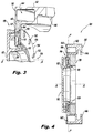
FIG. 2 is a perspective view of the nozzle of FIG. 1, showing the cold side of the nozzle;
FIG. 3 is a cross-sectional perspective view of a portion of the nozzle of FIG. 1, showing the liquid swirler and showing the outer air circuit with the heat shield removed;
FIG. 4 is a cross-sectional side elevation view of the nozzle of FIG. 1, showing the radial air swirler assembled onto the nozzle body;
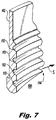
FIG. 5 is a perspective view of a the liquid swirler of FIG. 3, schematically showing one of the spiral liquid passages;
FIG. 6 is a perspective view of a portion of the nozzle of FIG. 1, showing the liquid swirler;
FIG. 7 is a cross-sectional perspective view of a portion of the liquid swirler of FIG. 6, showing one of the outlet orifices;
FIG. 8 is a cross-sectional elevation view of a portion of the nozzle of FIG. 1, schematically showing the inner air circuit, liquid circuit, and outer air circuit;
FIG. 9 is perspective view of the radial air swirler of FIG. 4, showing the radial swirl slots;
FIG. 10 is a perspective view of a plurality of nozzles of FIG. 1 assembled into a manifold assembly.
DETAILED DESCRIPTION OF THE PREFERRED EMBODIMENTS
Reference will now be made to the drawings wherein like reference numerals identify similar structural features or aspects of the subject disclosure. For purposes of explanation and illustration, and not limitation, a partial view of an exemplary embodiment of a nozzle in accordance with the disclosure is shown in FIG. 1 and is designated generally by reference character 100. Other embodiments of nozzles in accordance with the disclosure, or aspects thereof, are provided in FIGS. 2-10, as will be described. The systems and methods described herein can be used to atomize liquids, such as in atomizing fuel in a gas turbine engine.
Nozzle 100 includes a nozzle body 102 defining a liquid circuit 104 (identified in FIG. 3) extending from a liquid inlet 106 to a liquid outlet 108. Nozzle 100 is an assembly of components, one of which is the nozzle body 102, and other components of the assembly are descried herein below. FIG. 1 shows nozzle 100 from a downstream, hot side, e.g., from within a combustor into which nozzle 100 issues a spray of fuel. FIG. 2 shows nozzle 100 from an upstream cold side, e.g., from within a compressor that supplies pressurized air through nozzle 100 for combustion in on the hot side.
With reference to FIG. 3, the liquid circuit 104 includes a plurality of grooves for spiral liquid passages 110 spiraling radially inward relative to a spray axis A. Each of the spiral liquid passages lies in a plane P normal to the spray axis A. Plane P is identified in FIG. 4. Those skilled in the art will readily appreciate that while all of the spiral liquid passages 110 are defined in a common plane P, it is also possible for each spiral liquid passage to be defined in a separate respective plane perpendicular to the spray axis A without departing from the scope of this disclosure. An upstream heat shield 107 is mounted to an upstream portion of nozzle body 102.
With reference now to FIG. 5, the spiral liquid passages 110 are defined on an annular liquid swirler 112. FIG. 5 only shows one of the spiral liquid passages 110, but FIGS. 6 and 7 show four spiral liquid passages 110. Each spiral liquid passage 110 defines a respective inlet 111 and an outlet orifice 114 of the liquid outlet 108. Each outlet orifice 114 defines an orifice axis S that is has a tangential component relative to the spray axis A and lies in the plane P normal to the spray axis A (spray axis A and plane P are shown in FIG. 4). The angle of spray axis S relative to a true tangent about axis A is somewhat exaggerated in FIGS. 5 and 7 for sake of clarity, as spray axis S is nearly tangential to a circumferential direction about axis A (which is identified in FIG. 4). The swirl direction induced on liquid issuing from outlet orifices 114 is indicated by the larger arrow in FIG. 7. There can be more than four passages 110 depending on the diameter of the nozzle. In many applications, one exit occurs every 1 to 1.5 inches (2.54 to 3.81 cm) around the liquid swirler 112. One of the benefits of these passages 110 is they provide a certain resistance to the liquid flow due to friction. They can be relative large (e.g. greater than 0.020 inches or 0.0508 cm) in flow area which is desired to avoid flow blockage but provide sufficient resistance based on length to divide the flow uniformly around the circumference. The relatively long length helps in cooling the wetted surface of the liquid swirler 112 despite it being immersed in substantial hot, flowing air.
With reference now to FIG. 8, the nozzle body 102 includes an inner air circuit 116 passing inboard of the liquid outlet 108. The inner air circuit 116 extends radially inward from an inlet 118 thereof and turns in an axial direction, parallel with axis A in FIG. 4, to an outlet 120 thereof radially inboard of the liquid outlet 108. A radial air swirler 122 is mounted to the nozzle body 102. As shown in FIG. 9, radial air slots 124 are defined in the radial air swirler 122 to define an inlet 118 of the inner air circuit 116 shown in FIG. 8. The inner air circuit 116 and liquid circuit are in a co-swirling configuration, i.e. both circuits swirl in the same direction, however those skilled in the art will readily appreciate that any other suitable configuration can be used, including counter-swirling, without departing from the scope of this disclosure. Mixing therefor occurs in a very thin sheet at the exit of nozzle 100.
With continued reference to FIG. 8, the nozzle body 102 can include an outer air circuit 126 passing outboard of the liquid outlet 108. The outer air circuit 126 extends radially inward from an inlet 128 thereof and can turn in an axial direction, parallel to axis A shown in FIG. 4, to an outlet 130 thereof radially outboard of the liquid outlet 108. As shown in FIG. 3, the nozzle body 102 includes a plurality of spacers 132 extending from an annular face 134 of a downstream heat shield 136 of the nozzle body 102. The spacers 132 extend in a parallel direction to the spray axis A of FIG. 4. As shown in FIG. 8, a main heat shield 138 is mounted to the nozzle body 102 on a downstream face thereof, spaced apart from the nozzle body 102 by the spacers 132 (shown in FIG. 3), wherein the outer air circuit 128 is defined between the nozzle body 102, spacers 132, and heat shield 138. The spacers 132 define a non-tangential flow path for non-swirling issue of air through the outer air circuit 126. Inner and outer air circuits 116 and 128 sandwich the liquid from circuit 104 therebetween and shear the liquid for atomization. It is contemplated that the ratio of air flow can range from 50:50 to 40:60 inner to outer air flow, or any other suitable ratio. In an embodiment the nozzle body 102 comprises radial air swirler 122, upstream heat shield 107, liquid swirler 112, and downstream heat shield 136, which could be made as one additively manufactured component, or could be assembled as separate comments joined together.
With reference again to FIG. 4, nozzle body 102 includes an inner manifold ring segment 140 and an outer manifold ring segment 142, wherein outer ring segment 142 includes a liquid manifold passage 144 in fluid communication with the liquid inlet 106 of the liquid circuit 104. Inner ring segment 140 can optionally provide a similar liquid manifold passage, e.g., for multiple spray circuits or the like. Both the ring segments 140 and 142 include a bayonet features 146 configured to receive a corresponding bayonet feature of a combustor wall or combustor sliding support 148, shown in FIG. 1.
With reference now to FIG. 10, a manifold assembly 150 includes a plurality of nozzles 100 as described above. An outer manifold ring 152, made up of outer ring segments 142 of the respective nozzles 100, is in fluid communication with the liquid inlet 106 of each of the nozzles 100 to deliver liquid to the nozzles 100. The outer ring segments 142 are continuous with one another to form a continuous manifold ring 152. The nozzles 100 are circumferentially spaced apart around the manifold ring 152.
Assembly 150 includes an inner manifold ring 154, e.g. made up of inner ring segments 140 of the respective nozzles 100. The fuel nozzles 100 extend radially between the first and second manifold rings 152 and 154. Each manifold ring 152 and 154 can include bayonet features 146 as described above. Inner manifold ring 154 in the example shown in FIG. 10 is segmented as a stiffener ring, and is not therefore used for fuel manifolding. This accommodates thermal growth and shrinking of the nozzles 100 and outer manifold ring 152 relative to inner manifold ring 154. Outer ring 152 and nozzles 100 can be manufactured as a single integral component, e.g., using additive manufacturing. The heat shields 138 (shown in FIGS. 1 and 2) tile together to define an upstream combustor dome wall 156 (for sake of clarity only some of the heat shields 138 are shown tiled together in FIG. 10). Due to the tiling of wall 156, the inner and outer air circuits 116 and 126 (shown in FIG. 8) are the only pathway for air to pass through the combustor dome wall 156.
Potential advantages of nozzles and assemblies as described herein include elimination of bulk compared to conventional nozzles, e.g. with fuel passages defined in conical geometries. This very compact (flat) design does not take up much axial length and can reduce the axial length of the engine (shafts, case, and the like) saving substantial weight as well as reduce drag on the engine nacelle. Fuel can be distributed in a relatively large diameter using a serpentine distributor, e.g., liquid swirler 112. Air that is admitted as part of the nozzle can also be used to cool the backside of the combustor, e.g., the cold side of nozzles 100, before it enters the combustor. An internal fuel manifold, e.g., in the manifold rings 152 and 154, can reduce weight and eliminate numerous holes in the combustor case used for traditional fuel injectors to access the interior of the combustor case. Light weight ceramic matrix composite (CMC) materials can be advantageously used in the construction of the major elements.
The methods and systems of the present disclosure, as described above and shown in the drawings, provide for liquid injection with superior properties including compactness, light weight, and advantageous spray patternation. While the apparatus and methods of the subject disclosure have been shown and described with reference to preferred embodiments, those skilled in the art will readily appreciate that changes and/or modifications may be made thereto without departing from the scope of the subject disclosure.

Claims (11)

What is claimed is:
1. A nozzle comprising:
a nozzle body defining a liquid circuit extending from a liquid inlet to a liquid outlet, wherein the liquid circuit includes at least one spiral liquid passage spiraling radially inward relative to a spray axis, wherein each of the at least one spiral liquid passages lies in a plane normal to the spray axis, wherein each of the at least one spiral liquid passage defines a respective outlet orifice of the liquid outlet, wherein each outlet orifice defines an orifice axis that is tangential relative to the spray axis and lies in the plane normal to the spray axis, wherein a radial cross-section through the nozzle body, relative to the spray axis, cuts through all spiral liquid passages, namely a cross-section as viewed in a cross-sectional side-elevation view, viewing toward the spray axis, which runs in a direction going across the view, wherein each spiral liquid passage is defined in and issues from a plane perpendicular to the spray axis into a respective air passage that follows a path parallel to the spray axis.
2. A nozzle as recited in claim 1, wherein the nozzle body includes an inner air circuit passing inboard of the liquid outlet.
3. A nozzle as recited in claim 2, wherein the inner air circuit extends radially inward with a tangential swirl from an inlet thereof and turns in an axial direction to an outlet thereof radially inboard of the liquid outlet.
4. A nozzle as recited in claim 2, further comprising a radial air swirler mounted to the nozzle body, wherein radial air slots defined in the radial air swirler define an inlet of the inner air circuit.
5. A nozzle as recited in claim 2, wherein the inner air circuit and liquid circuit are in a co-swirling configuration.
6. A nozzle as recited in claim 1, wherein the nozzle body includes an outer air circuit passing outboard of the liquid outlet.
7. A nozzle as recited in claim 6, wherein the outer air circuit extends radially inward from an inlet thereof and turns in an axial direction to an outlet thereof radially outboard of the liquid outlet.
8. A nozzle as recited in claim 1, wherein the nozzle body includes inner and outer manifold ring segments, wherein at least one of the ring segments includes a liquid manifold passage in fluid communication with the liquid inlet of the liquid circuit.
9. A nozzle as recited in claim 8, wherein at least one of the ring segments includes a bayonet feature configured to receive a corresponding bayonet feature of a combustor wall or combustor sliding support.
10. A nozzle comprising:
a nozzle body defining a liquid circuit extending from a liquid inlet to a liquid outlet, wherein the liquid circuit includes at least one spiral liquid passage spiraling radially inward relative to a spray axis, wherein each of the at least one spiral liquid passages lies in a plane normal to the spray axis, wherein a radial cross-section through the nozzle body, relative to the spray axis, cuts through all spiral liquid passages, namely a cross-section as viewed in a cross-sectional side-elevation view, viewing toward the spray axis, which runs in a direction going across the view, wherein the nozzle body includes an outer air circuit passing outboard of the liquid outlet, wherein the nozzle body includes a plurality of spacers extending from an annular face of the nozzle body in a parallel direction to the spray axis, and further comprising a heat shield mounted to the nozzle body, spaced apart from the nozzle body by the plurality of spacers, wherein the outer air circuit is defined between the nozzle body, the plurality of spacers, and heat shield, wherein each spiral liquid passage is defined in and issues from a plane perpendicular to the spray axis into a respective air passage that follows a path parallel to the spray axis.
11. A nozzle as recited in claim 10, wherein the spacers define a non-tangential flow path for non-swirling flow of air through the outer air circuit.
US15/268,211 2016-09-16 2016-09-16 Nozzles with internal manifolding Active US10876477B2 (en)

Priority Applications (5)

Application Number Priority Date Filing Date Title
US15/268,211 US10876477B2 (en) 2016-09-16 2016-09-16 Nozzles with internal manifolding
EP19183683.2A EP3567314B1 (en) 2016-09-16 2017-09-18 Nozzles with internal manifolding
EP17191544.0A EP3296639B1 (en) 2016-09-16 2017-09-18 Nozzles with internal manifolding
US17/129,299 US11680527B2 (en) 2016-09-16 2020-12-21 Nozzles with internal manifolding
US18/201,971 US20230296054A1 (en) 2016-09-16 2023-05-25 Nozzles with internal manifolding

Applications Claiming Priority (1)

Application Number Priority Date Filing Date Title
US15/268,211 US10876477B2 (en) 2016-09-16 2016-09-16 Nozzles with internal manifolding

Related Child Applications (1)

Application Number Title Priority Date Filing Date
US17/129,299 Division US11680527B2 (en) 2016-09-16 2020-12-21 Nozzles with internal manifolding

Publications (2)

Publication Number Publication Date
US20180080384A1 US20180080384A1 (en) 2018-03-22
US10876477B2 true US10876477B2 (en) 2020-12-29

Family

ID=59901416

Family Applications (3)

Application Number Title Priority Date Filing Date
US15/268,211 Active US10876477B2 (en) 2016-09-16 2016-09-16 Nozzles with internal manifolding
US17/129,299 Active 2036-12-16 US11680527B2 (en) 2016-09-16 2020-12-21 Nozzles with internal manifolding
US18/201,971 Pending US20230296054A1 (en) 2016-09-16 2023-05-25 Nozzles with internal manifolding

Family Applications After (2)

Application Number Title Priority Date Filing Date
US17/129,299 Active 2036-12-16 US11680527B2 (en) 2016-09-16 2020-12-21 Nozzles with internal manifolding
US18/201,971 Pending US20230296054A1 (en) 2016-09-16 2023-05-25 Nozzles with internal manifolding

Country Status (2)

Country Link
US (3) US10876477B2 (en)
EP (2) EP3296639B1 (en)

Families Citing this family (3)

* Cited by examiner, † Cited by third party
Publication number Priority date Publication date Assignee Title
FR3084731B1 (en) * 2019-02-19 2020-07-03 Safran Aircraft Engines COMBUSTION CHAMBER FOR A TURBOMACHINE
US11187155B2 (en) * 2019-07-22 2021-11-30 Delavan Inc. Sectional fuel manifolds
EP3904768B1 (en) 2020-04-28 2024-04-17 Collins Engine Nozzles, Inc. Fluid nozzle

Citations (25)

* Cited by examiner, † Cited by third party
Publication number Priority date Publication date Assignee Title
US2172383A (en) 1936-03-23 1939-09-12 Honn Harlan Verne Fuel injection device
US3570242A (en) * 1970-04-20 1971-03-16 United Aircraft Corp Fuel premixing for smokeless jet engine main burner
US3853273A (en) * 1973-10-01 1974-12-10 Gen Electric Axial swirler central injection carburetor
US3901446A (en) * 1974-05-09 1975-08-26 Us Air Force Induced vortex swirler
US4180974A (en) * 1977-10-31 1980-01-01 General Electric Company Combustor dome sleeve
US4653278A (en) 1985-08-23 1987-03-31 General Electric Company Gas turbine engine carburetor
US4842197A (en) * 1986-12-10 1989-06-27 Mtu Motoren-Und Turbinen-Union Gmbh Fuel injection apparatus and associated method
US4887962A (en) 1988-02-17 1989-12-19 Shell Oil Company Partial combustion burner with spiral-flow cooled face
US5353599A (en) * 1993-04-29 1994-10-11 United Technologies Corporation Fuel nozzle swirler for combustors
US6003781A (en) 1996-11-07 1999-12-21 Bmw Rolls-Royce Gmbh Fuel injection device with a liquid-cooled injection nozzle for a combustion chamber of a gas turbine
US6247317B1 (en) 1998-05-22 2001-06-19 Pratt & Whitney Canada Corp. Fuel nozzle helical cooler
US6775984B2 (en) 2000-11-21 2004-08-17 Snecma Moteurs Full cooling of main injectors in a two-headed combustion chamber
US20050133642A1 (en) 2003-10-20 2005-06-23 Leif Rackwitz Fuel injection nozzle with film-type fuel application
US20050279862A1 (en) * 2004-06-09 2005-12-22 Chien-Pei Mao Conical swirler for fuel injectors and combustor domes and methods of manufacturing the same
US7654088B2 (en) 2004-02-27 2010-02-02 Pratt & Whitney Canada Corp. Dual conduit fuel manifold for gas turbine engine
US7891193B2 (en) 2006-01-09 2011-02-22 Snecma Cooling of a multimode fuel injector for combustion chambers, in particular of a jet engine
US8074452B2 (en) 2002-08-30 2011-12-13 Pratt & Whitney Canada Corp. Nested channel ducts for nozzle construction and the like
US8186163B2 (en) 2007-08-10 2012-05-29 Snecma Multipoint injector for turbomachine
US20120186259A1 (en) 2011-01-26 2012-07-26 United Technologies Corporation Fuel injector assembly
US20120228397A1 (en) 2011-03-10 2012-09-13 Delavan Inc Systems and method for cooling a staged airblast fuel injector
US8347630B2 (en) 2008-09-03 2013-01-08 United Technologies Corp Air-blast fuel-injector with shield-cone upstream of fuel orifices
US20140318137A1 (en) 2008-04-11 2014-10-30 General Electric Company Fuel nozzle
US20140339339A1 (en) 2011-11-03 2014-11-20 Delavan Inc Airblast injectors for multipoint injection and methods of assembly
US20150014444A1 (en) * 2012-02-15 2015-01-15 Toyota Jidosha Kabushiki Kaisha Fuel injection valve, and fuel injection apparatus provided with the same
WO2015092206A1 (en) 2013-12-20 2015-06-25 Snecma Annular combustion chamber in a turbine engine

Family Cites Families (4)

* Cited by examiner, † Cited by third party
Publication number Priority date Publication date Assignee Title
US4813398A (en) * 1988-05-09 1989-03-21 Hobart Corporation Convection oven
US4867132A (en) * 1988-11-23 1989-09-19 Garland Commercial Industries, Inc. Gas fired convection oven with improved air delivery and heat exchange structure
US4963091A (en) * 1989-10-23 1990-10-16 Surface Combustion, Inc. Method and apparatus for effecting convective heat transfer in a cylindrical, industrial heat treat furnace
US6925809B2 (en) * 1999-02-26 2005-08-09 R. Jan Mowill Gas turbine engine fuel/air premixers with variable geometry exit and method for controlling exit velocities

Patent Citations (28)

* Cited by examiner, † Cited by third party
Publication number Priority date Publication date Assignee Title
US2172383A (en) 1936-03-23 1939-09-12 Honn Harlan Verne Fuel injection device
US3570242A (en) * 1970-04-20 1971-03-16 United Aircraft Corp Fuel premixing for smokeless jet engine main burner
US3853273A (en) * 1973-10-01 1974-12-10 Gen Electric Axial swirler central injection carburetor
US3901446A (en) * 1974-05-09 1975-08-26 Us Air Force Induced vortex swirler
US4180974A (en) * 1977-10-31 1980-01-01 General Electric Company Combustor dome sleeve
US4653278A (en) 1985-08-23 1987-03-31 General Electric Company Gas turbine engine carburetor
US4842197A (en) * 1986-12-10 1989-06-27 Mtu Motoren-Und Turbinen-Union Gmbh Fuel injection apparatus and associated method
US4887962A (en) 1988-02-17 1989-12-19 Shell Oil Company Partial combustion burner with spiral-flow cooled face
US5353599A (en) * 1993-04-29 1994-10-11 United Technologies Corporation Fuel nozzle swirler for combustors
US6003781A (en) 1996-11-07 1999-12-21 Bmw Rolls-Royce Gmbh Fuel injection device with a liquid-cooled injection nozzle for a combustion chamber of a gas turbine
US6247317B1 (en) 1998-05-22 2001-06-19 Pratt & Whitney Canada Corp. Fuel nozzle helical cooler
US6775984B2 (en) 2000-11-21 2004-08-17 Snecma Moteurs Full cooling of main injectors in a two-headed combustion chamber
US8074452B2 (en) 2002-08-30 2011-12-13 Pratt & Whitney Canada Corp. Nested channel ducts for nozzle construction and the like
US20050133642A1 (en) 2003-10-20 2005-06-23 Leif Rackwitz Fuel injection nozzle with film-type fuel application
US9033263B2 (en) 2003-10-20 2015-05-19 Rolls-Royce Deutschland Ltd & Co Kg Fuel injection nozzle with film-type fuel application
US7654088B2 (en) 2004-02-27 2010-02-02 Pratt & Whitney Canada Corp. Dual conduit fuel manifold for gas turbine engine
US20050279862A1 (en) * 2004-06-09 2005-12-22 Chien-Pei Mao Conical swirler for fuel injectors and combustor domes and methods of manufacturing the same
US7891193B2 (en) 2006-01-09 2011-02-22 Snecma Cooling of a multimode fuel injector for combustion chambers, in particular of a jet engine
US8186163B2 (en) 2007-08-10 2012-05-29 Snecma Multipoint injector for turbomachine
US20120186083A1 (en) 2007-08-10 2012-07-26 Snecma Multipoint injector for turbomachine
US8959772B2 (en) * 2007-08-10 2015-02-24 Snecma Multipoint injector for turbomachine
US20140318137A1 (en) 2008-04-11 2014-10-30 General Electric Company Fuel nozzle
US8347630B2 (en) 2008-09-03 2013-01-08 United Technologies Corp Air-blast fuel-injector with shield-cone upstream of fuel orifices
US20120186259A1 (en) 2011-01-26 2012-07-26 United Technologies Corporation Fuel injector assembly
US20120228397A1 (en) 2011-03-10 2012-09-13 Delavan Inc Systems and method for cooling a staged airblast fuel injector
US20140339339A1 (en) 2011-11-03 2014-11-20 Delavan Inc Airblast injectors for multipoint injection and methods of assembly
US20150014444A1 (en) * 2012-02-15 2015-01-15 Toyota Jidosha Kabushiki Kaisha Fuel injection valve, and fuel injection apparatus provided with the same
WO2015092206A1 (en) 2013-12-20 2015-06-25 Snecma Annular combustion chamber in a turbine engine

Non-Patent Citations (2)

* Cited by examiner, † Cited by third party
Title
Extended European Search Report dated Aug. 1, 2019, issued during the prosecution of European Patent Application No. EP 19183683.2.
Extended European Search Report dated Jan. 22, 2018, issued during the prosecution of European Patent Application No. 17191544.0 (8 pages).

Also Published As

Publication number Publication date
US11680527B2 (en) 2023-06-20
EP3296639B1 (en) 2019-07-10
US20230296054A1 (en) 2023-09-21
EP3567314B1 (en) 2020-12-30
EP3567314A1 (en) 2019-11-13
US20180080384A1 (en) 2018-03-22
US20210108565A1 (en) 2021-04-15
EP3296639A1 (en) 2018-03-21

Similar Documents

Publication Publication Date Title
US11680527B2 (en) Nozzles with internal manifolding
US11111888B2 (en) Fuel nozzles
CA2845146C (en) Combustor for gas turbine engine
EP3143334B1 (en) Pre-film liquid fuel cartridge
US10570821B2 (en) Pre-film liquid fuel cartridge
US20140291418A1 (en) Multi-circuit airblast fuel nozzle
US20140041390A1 (en) Lean burn injectors having multiple pilot circuits
US20150354517A1 (en) Direct injection multipoint nozzle
CA2845145C (en) Combustor for gas turbine engine
US10731862B2 (en) Systems and methods for a multi-fuel premixing nozzle with integral liquid injectors/evaporators
EP3156732B1 (en) Airblast fuel injectors
US20230071579A1 (en) Airblast fuel nozzle
US7021562B2 (en) Macrolaminate direct injection nozzle
EP2778370B1 (en) Combustor for gas turbine engine
CN108474556B (en) Fuel injector with multi-tube gas distribution
EP4001764B1 (en) Fuel swirler for pressure fuel nozzles
US11454395B2 (en) Thermal resistant air caps

Legal Events

Date Code Title Description
AS Assignment

Owner name: DELAVAN INC, IOWA

Free format text: ASSIGNMENT OF ASSIGNORS INTEREST;ASSIGNORS:PROCIW, LEV A.;RYON, JASON A.;REEL/FRAME:039776/0207

Effective date: 20160916

STPP Information on status: patent application and granting procedure in general

Free format text: FINAL REJECTION MAILED

STPP Information on status: patent application and granting procedure in general

Free format text: DOCKETED NEW CASE - READY FOR EXAMINATION

STPP Information on status: patent application and granting procedure in general

Free format text: NON FINAL ACTION MAILED

STPP Information on status: patent application and granting procedure in general

Free format text: RESPONSE TO NON-FINAL OFFICE ACTION ENTERED AND FORWARDED TO EXAMINER

STPP Information on status: patent application and granting procedure in general

Free format text: FINAL REJECTION MAILED

STPP Information on status: patent application and granting procedure in general

Free format text: DOCKETED NEW CASE - READY FOR EXAMINATION

STCF Information on status: patent grant

Free format text: PATENTED CASE

AS Assignment

Owner name: COLLINS ENGINE NOZZLES, INC., IOWA

Free format text: CHANGE OF NAME;ASSIGNOR:DELAVAN INC;REEL/FRAME:060158/0981

Effective date: 20220106