EP1526321B1 - Werkzeug zum Erzeugen einer Öffnung in einer Fluidleitung - Google Patents
Werkzeug zum Erzeugen einer Öffnung in einer Fluidleitung Download PDFInfo
- Publication number
- EP1526321B1 EP1526321B1 EP04104943A EP04104943A EP1526321B1 EP 1526321 B1 EP1526321 B1 EP 1526321B1 EP 04104943 A EP04104943 A EP 04104943A EP 04104943 A EP04104943 A EP 04104943A EP 1526321 B1 EP1526321 B1 EP 1526321B1
- Authority
- EP
- European Patent Office
- Prior art keywords
- hole
- wall
- fluid line
- tool according
- lever
- Prior art date
- Legal status (The legal status is an assumption and is not a legal conclusion. Google has not performed a legal analysis and makes no representation as to the accuracy of the status listed.)
- Expired - Lifetime
Links
- 239000012530 fluid Substances 0.000 title claims abstract description 29
- XLYOFNOQVPJJNP-UHFFFAOYSA-N water Substances O XLYOFNOQVPJJNP-UHFFFAOYSA-N 0.000 claims abstract description 6
- 239000002184 metal Substances 0.000 claims abstract description 5
- 230000035515 penetration Effects 0.000 claims description 3
- 229910000760 Hardened steel Inorganic materials 0.000 claims description 2
- 238000005096 rolling process Methods 0.000 claims description 2
- 229910010293 ceramic material Inorganic materials 0.000 claims 1
- 238000006073 displacement reaction Methods 0.000 claims 1
- 230000000149 penetrating effect Effects 0.000 abstract description 2
- 238000005553 drilling Methods 0.000 description 4
- 230000008719 thickening Effects 0.000 description 2
- 230000005540 biological transmission Effects 0.000 description 1
- 239000000919 ceramic Substances 0.000 description 1
- 238000003780 insertion Methods 0.000 description 1
- 230000037431 insertion Effects 0.000 description 1
- 230000002262 irrigation Effects 0.000 description 1
- 238000003973 irrigation Methods 0.000 description 1
- 239000007788 liquid Substances 0.000 description 1
- 238000005476 soldering Methods 0.000 description 1
- 238000003466 welding Methods 0.000 description 1
Images

Classifications
-
- F—MECHANICAL ENGINEERING; LIGHTING; HEATING; WEAPONS; BLASTING
- F16—ENGINEERING ELEMENTS AND UNITS; GENERAL MEASURES FOR PRODUCING AND MAINTAINING EFFECTIVE FUNCTIONING OF MACHINES OR INSTALLATIONS; THERMAL INSULATION IN GENERAL
- F16L—PIPES; JOINTS OR FITTINGS FOR PIPES; SUPPORTS FOR PIPES, CABLES OR PROTECTIVE TUBING; MEANS FOR THERMAL INSULATION IN GENERAL
- F16L41/00—Branching pipes; Joining pipes to walls
- F16L41/04—Tapping pipe walls, i.e. making connections through the walls of pipes while they are carrying fluids; Fittings therefor
- F16L41/06—Tapping pipe walls, i.e. making connections through the walls of pipes while they are carrying fluids; Fittings therefor making use of attaching means embracing the pipe
- F16L41/065—Tapping pipe walls, i.e. making connections through the walls of pipes while they are carrying fluids; Fittings therefor making use of attaching means embracing the pipe without removal of material
-
- B—PERFORMING OPERATIONS; TRANSPORTING
- B21—MECHANICAL METAL-WORKING WITHOUT ESSENTIALLY REMOVING MATERIAL; PUNCHING METAL
- B21D—WORKING OR PROCESSING OF SHEET METAL OR METAL TUBES, RODS OR PROFILES WITHOUT ESSENTIALLY REMOVING MATERIAL; PUNCHING METAL
- B21D28/00—Shaping by press-cutting; Perforating
- B21D28/24—Perforating, i.e. punching holes
- B21D28/28—Perforating, i.e. punching holes in tubes or other hollow bodies
Definitions
- the invention relates to a tool for producing an opening in the wall of a fluid line, in particular a metal tube for pressurized water, with a receptacle for the fluid line, with a punch for penetrating the wall, with a hand-operated lever for driving the punch and with fixing means for fixing the Fluid line in the receptacle.
- US 3,395,724 shows such a tool for piercing conduits to remove the liquid in a conduit system.
- fluid lines can be provided with an opening to thereby create a branch for attaching a branch line or a nozzle.
- Such tools are used primarily for creating openings in plastic pipes, which serve for the guidance of water under low pressure, for example for irrigation systems.
- high forces are required to introduce such an opening in the wall by means of a hand-operated lever. If you do not work the same with sufficient force to penetrate the wall, it is necessary with below that is set again. In this case, it may happen that the fluid line slips in the receptacle and thus adjacent to the subsequent opening damage to the walls occur. This can lead to unwanted leaks.
- No. 6,367,362 B1 discloses a cam mechanism with which high forces can be generated.
- US 3,939,683 describes a drill with an angled surface.
- the problem underlying the invention is to provide a tool for generating an opening in the wall of a fluid line, with which the opening can be generated safely, reliably and with little effort at a predetermined location.
- the punch has a front first area with a first angle and a second area adjacent to the first area with a smaller second angle.
- the first area with the relatively large first angle is used when attaching the punch to the wall first.
- This first area causes a denting and a piercing of the wall in a relatively small area.
- This relatively large forces are transmitted.
- the opening of the wall increases more and more. So that in this case no undesirably large forces occur, the opening angle in the second region with a larger diameter is relatively small.
- the fixing cause thereby a reliable fixing of the fluid line in the recording. Even with a settling and reapplying the tool remains at the once set position. In this way, an opening in the wall of a fluid line at a desired position can be easily and reliably create even if, for example, the opening in the wall of a metal tube for pressurized water to be generated, so that this large forces are required.
- the receptacle is formed in a clampable to a base jaw.
- the fluid line can be securely clamped between the jaw and the base.
- It may also be provided by means of a handle operable articulated lever for clamping the jaw to the base.
- an adjusting means for adjusting the fixing force can be as a simple and reliable operation for clamping the fluid line in the receptacle in the manner of a grip pliers achieve.
- the punch is coupled by means of a gear with the lever.
- the transmission may be, for example, a cam mechanism.
- the cam gear has an eccentrically mounted cam with a cam track which cooperates with a cam for driving the punch.
- the cam has a rotatably mounted for rolling on the cam track ball or roller.
- This ball or roller may be made of ceramic or hardened steel.
- the punch may also be slidably disposed in a housing having the receptacle.
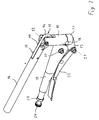
- Fig. 1 shows a tool for creating an opening in the wall of a fluid conduit with the invention features.
- the tool has a housing 10 which is rigidly connected to a lever 11.
- the lever 11 may be screwed, riveted or even integrally with the housing 10, for example be educated.
- an eccentric disc 13 is arranged, which has a cam track 14.
- the eccentric disc 13 is connected at its side facing away from the housing 10 by means of two bolts 15 with a lever 16.
- a jaw 17 is arranged at the end facing away from the axis 12 of the housing 10 facing this .
- the housing 10 and the jaw 17 each have on their mutually facing surfaces on a partially cylindrical recess, which together form a receptacle 18 for receiving a fluid line.
- the clamping jaw 17 is rigidly connected to an articulated lever 19.
- the rigid connection can be ensured for example by means of screwing, soldering or welding or by means of a one-piece design.
- the articulated lever 19 is pivotally mounted on the lever 11 by means of a first axis 20 and also pivotally mounted on a handle 22 by means of a second axis 21.
- the handle 22 is in turn connected by means of a lever not shown in the figure with a knurled screw 24 which is screwed into a nut 23 at the end facing away from the housing 10 of the lever 11.
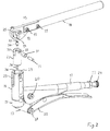
- Fig. 2 shows an exploded view of the tool of Fig. 1.
- the eccentric disk 13 has a recess 25 concentric with the cam track 14.
- a guide 27 is arranged for a punch 28 beyond.
- the housing 10 also has two slots 29 for the eccentric disc 13.
- the punch 28 is arranged in a bore of the guide 27.
- the guide 27 has an approximately cylindrical shape and has at its the eccentric disk 13 side facing one of these associated slots 30.
- the eccentric disc 13 is arranged in the region of the slit 30, wherein a roller 31 is arranged in the recess 25 and fixed by means of a bolt 32 in a bore 33 of the guide 27.
- a screw 34 serves to attach the punch 28 to the guide 27.
- the screw 34 has on its side facing the roller 31 a hexagon socket 35 on.
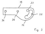
- Fig. 3 shows the eccentric disc 13 in an enlarged view.
- the eccentric disk has two bores 36 assigned to the bolts 15 and a bore 37 assigned to the axis 12.
- the recess 25 and the cam track 14 are concentric with each other and arranged eccentrically to the bore 37.
- Fig. 4 shows the punch 28 in an enlarged view.
- the punch 28 has at its tip a first region 38 and a second region 39 adjacent thereto.
- the first area 38 is relatively blunt, while the second area 39 is sharper, that is, has a smaller angle than the first area 38.
- the punch 28 has a thickening 40, by means of which on the one hand falling out of the punch 28 is prevented from the guide 27 and the other hand serves as a repository for the cam 34.
- a fluid line to be processed is first placed in the receptacle 18 and fixed there by pressing the handle 22 against the lever 11.
- the angle of attack of the articulated lever 19 in a closed state of the tool in which the handle 22 rests against the lever 11, by screwing the knurled screw 24 into the nut 23 can be adjusted.
- the punch 28 is driven by pivoting down the lever 16 from a nearly right angle to the lever 11 position in a nearly parallel to the lever 11 position in the wall of the fluid line.
- the first area 38 of the punch 28 comes into contact with the wall, where it causes it to deform in a relatively small area. If then the first portion 38 deformed the wall so far or has already pressed a small opening in this, that the second portion 39 comes into contact with the wall, is here because of the smaller pitch of the second portion 39 at a same stroke of the punch 28 only still causes a smaller increase in the opening in the wall of the fluid line. In this way the required force is reduced.
- the eccentric arrangement of the cam track 14 to the axis 12, that at the beginning of generating the opening in the wall of the fluid line in the state in which the lever 16 is arranged almost perpendicular to the lever 11, between the contact point of the cam track 14 and the axis 12 is formed only a relatively small lever arm. As a result, a particularly large force is generated for piercing the first region into the wall of the fluid line.
- the lever arm between the respective position on the cam track 14 and the axis 12 is more and more increased, wherein an operator in this ever further swung down state can spend an ever greater force, so that in combination with the lower slope of the second portion 39 a effortless penetration of the punch 28 is ensured in the wall of the fluid line.
- the roller 31 is disposed in the interior of the recess 25 and causes when opening, so in the right-angled position pivoting of the lever 16, an upward pull of the guide 27 from the housing 10. When pivoting down the lever 16, the roller 31 rolls on the cam track 14 and can transfer the force thus generated to the punch 28 so virtually frictionless.
Landscapes
- Engineering & Computer Science (AREA)
- General Engineering & Computer Science (AREA)
- Mechanical Engineering (AREA)
- Perforating, Stamping-Out Or Severing By Means Other Than Cutting (AREA)
- Punching Or Piercing (AREA)
- Drilling Tools (AREA)
Description
- Die Erfindung betrifft ein Werkzeug zum Erzeugen einer Öffnung in der Wandung einer Fluidleitung, insbesondere eines Metallrohres für Druckwasser, mit einer Aufnahme für die Fluidleitung, mit einem Lochstempel zum Durchdringen der Wandung, mit einem handbetätigbaren Hebel zum Antreiben des Lochstempels und mit Fixiermitteln zum Fixieren der Fluidleitung in der Aufnahme.
- Die US 3,395,724 zeigt ein solches Werkzeug zum Anstechen von Leitungen, um die in einem Leitungssystem befindliche Flüssigkeit zu entfernen.
- Mittels eines solchen Werkzeuges lassen sich Fluidleitungen mit einer Öffnung versehen, um hierdurch eine Abzweigung zum Anbringen einer Verzweigungsleitung oder einer Düse zu erstellen. Derartige Werkzeuge werden vornehmlich zum Erstellen von Öffnungen in Kunststoffleitungen verwendet, die für die Leitung von Wasser unter geringem Druck beispielsweise für Bewässerungsanlagen dienen. Insbesondere zum Erzeugen einer Öffnung in der Wandung eines Metallrohres, beispielsweise eines solchen für Druckwasser, sind hohe Kräfte erforderlich, um mittels eines handbetätigten Hebels eine solche Öffnung in die Wandung einzubringen. Wenn nicht gleich mit ausreichender Kraft zum Durchdringen der Wandung gearbeitet wird, ist es mit unter erforderlich, daß erneut angesetzt wird. In diesem Fall kann es vorkommen, daß die Fluidleitung in der Aufnahme verrutscht und somit benachbart der späteren Öffnung Beschädigungen der Wandungen auftreten. Dies kann zu unerwünschten Leckagen führen.
- Der US 6,367,362 B1 ist ein Kurvengetriebe zu entnehmen, mit dem sich hohe Kräfte erzeugen lassen. Die US 3,939,683 beschreibt einen Bohrer mit einer gewinkelten Oberfläche.
- Das der Erfindung zugrunde liegende Problem ist es, ein Werkzeug zum Erzeugen einer Öffnung in der Wandung einer Fluidleitung anzugeben, mit dem sich die Öffnung an einer vorgegebenen Stelle sicher, zuverlässig und mit geringem Kraftaufwand erzeugen läßt.
- Das Problem wird erfindungsgemäß dadurch gelöst, daß bei einem Werkzeug der eingangs genannten Art der Lochstempel einen vorderen ersten Bereich mit einem ersten Winkel und einen dem ersten Bereich benachbarten zweiten Bereich mit einem kleineren zweiten Winkel aufweist.
- Auf diese Weise kommt beim Ansetzen des Lochstempels an die Wandung zunächst der erste Bereich mit dem verhältnismäßig großen ersten Winkel zum Einsatz. Dieser erste Bereich bewirkt ein Eindellen und ein Einstechen der Wandung in einem verhältnismäßig kleinen Bereich. Hierbei werden relativ große Kräfte übertragen. Nachdem der erste Bereich in die Wandung eingedrungen ist, vergrößert sich die Öffnung der Wandung mehr und mehr. Damit hierbei keine unerwünscht großen Kräfte auftreten, ist der Öffnungswinkel in dem zweiten Bereich mit größerem Durchmesser verhältnismäßig klein. Dadurch bewirkt ein verhältnismäßig großes Einschieben des Lochstempels in die Öffnung nur eine verhältnismäßig geringe Änderung des Durchmessers der Öffnung. Dies ist mit verhältnismäßig geringem Kraftaufwand möglich. Die Fixiermittel bewirken dabei ein zuverlässiges Fixieren der Fluidleitung in der Aufnahme. Selbst bei einem Absetzen und erneuten Ansetzen verbleibt das Werkzeug an der einmal eingestellten Position. Auf diese Weise läßt sich einfach und zuverlässig auch dann eine Öffnung in der Wandung einer Fluidleitung an einer gewünschten Position erstellen, wenn beispielsweise die Öffnung in der Wandung eines Metallrohres für Druckwasser erzeugt werden soll, so daß hierfür große Kraftanstrengungen erforderlich sind.
- Bei einer Weiterbildung der Erfindung ist die Aufnahme in einer an eine Basis klemmbaren Klemmbacke ausgebildet. Auf diese Weise kann die Fluidleitung sicher zwischen der Klemmbacke und der Basis festgeklemmt werden. Es kann außerdem ein mittels eines Griffstückes betätigbarer Gelenkhebel zum Klemmen der Klemmbacke an die Basis vorgesehen sein. Insbesondere in Verbindung mit einem Verstellmittel zum Verstellen der Fixierkraft läßt sich so ein einfaches und zuverlässiges Bedienen zum Festklemmen der Fluidleitung in der Aufnahme nach Art einer Gripzange erreichen.
- Eine andere Weiterbildung der Erfindung zeichnet sich dadurch aus, daß der Lochstempel mittels eines Getriebes mit dem Hebel gekoppelt ist. Auf diese Weise läßt sich die erforderliche Kraft zum Eintreiben des Lochstempels in die Wandung der Fluidleitung reduzieren. Dadurch wird die Betätigung besonders einfach. Das Getriebe kann beispielsweise ein Kurvengetriebe sein. Eine Weiterbildung zeichnet sich dadurch aus, daß das Kurvengetriebe eine exzentrisch gelagerte Kurvenscheibe mit einer Nockenbahn aufweist, die mit einer Nocke zum Antreiben des Lochstempels zusammenwirkt. Vorzugsweise weist die Nocke eine drehbar zum Abrollen auf der Nockenbahn gelagerte Kugel oder Rolle auf. Diese Kugel oder Rolle kann aus Keramik oder gehärtetem Stahl bestehen. Dieser Aufbau ist besonders einfach und liefert gleichermaßen zuverlässig eine hohe Druckkraft zum Einpressen des Lochstempels in die Wandung der Fluidleitung, ohne daß hierzu ein besonders hoher Kraftaufwand an dem handbetätigbaren Hebel erforderlich ist.
- Der Lochstempel kann außerdem verschiebbar in einem die Aufnahme aufweisenden Gehäuse angeordnet sein. Insbesondere bietet sich eine Führung für den Lochstempel an. Dadurch läßt sich ein großer Hub des Lochstempels bei gleichzeitig präziser Führung zum Erzeugen einer Öffnung hoher Qualität in der Wandung der Fluidleitung erzielen.
- Im folgenden wird ein Ausführungsbeispiel der Erfindung anhand der Zeichnungen näher beschrieben. Es zeigen:
- Fig. 1
- eine perspektivische Darstellung eines Werkzeugs mit den Erfindungsmerkmalen,
- Fig. 2
- eine Explosionsdarstellung des Werkzeugs von Fig. 1,
- Fig. 3
- eine Draufsicht auf eine Exzenterscheibe des Werkzeugs mit den Erfindungsmerkmalen, und
- Fig. 4
- einen Lochstempel des Werkzeugs mit den Erfindungsmerkmalen.
- Fig. 1 zeigt ein Werkzeug zum Erzeugen einer Öffnung in der Wandung einer Fluidleitung mit den Erfindungsmerkmalen. Das Werkzeug weist ein Gehäuse 10 auf, das mit einem Hebel 11 starr verbunden ist. Der Hebel 11 kann mit dem Gehäuse 10 beispielsweise verschraubt, vernietet oder auch einstückig mit diesem ausgebildet sein. In einem oberen Bereich des Gehäuses 10 ist schwenkbar um eine Achse 12 eine Exzenterscheibe 13 angeordnet, die eine Nockenbahn 14 aufweist. Die Exzenterscheibe 13 ist an ihrer von dem Gehäuse 10 abgewandten Seite mittels zweier Bolzen 15 mit einem Hebel 16 verbunden.
- An dem von der Achse 12 abgewandten Ende des Gehäuses 10 ist diesen zugewandt eine Klemmbacke 17 angeordnet. Das Gehäuse 10 und die Klemmbacke 17 weisen an ihren einander zugewandten Flächen jeweils eine teilzylinderförmige Aussparung auf, die gemeinsam eine Aufnahme 18 zum Aufnehmen einer Fluidleitung bilden.
- Am von der Aufnahme 18 abgewandten Ende ist die Klemmbacke 17 starr mit einem Gelenkhebel 19 verbunden. Die starre Verbindung kann beispielsweise mittels Verschrauben, Verlöten oder Verschweißen oder auch mittels einer einstückigen Ausführung gewährleistet sein. Der Gelenkhebel 19 ist mittels einer ersten Achse 20 schwenkbar an dem Hebel 11 und mittels einer zweiten Achse 21 ebenfalls schwenkbar an einem Griffstück 22 angeordnet. Das Griffstück 22 ist wiederum mittels eines nicht in der Fig. dargestellten Hebels mit einer Rändelschraube 24 verbunden, die in eine Mutter 23 am von dem Gehäuse 10 abgewandten Ende des Hebels 11 geschraubt ist. Auf diese Weise kann mittels Einschrauben der Rändelschraube 24 in die Mutter 23 ein Verstellen des Anstellwinkels des Gelenkhebels 19 in einem Zustand, bei den das Griffstück 22 an den Hebel 11 anliegt nach Art einer sogenannten Gripzange, bewirkt werden.
- Fig. 2 zeigt eine Explosionsdarstellung des Werkzeugs von Fig. 1. Gleiche Elemente tragen die gleichen Bezugsziffern. Wie sich der Fig. entnehmen läßt, weist die Exzenterscheibe 13 eine zu der Nockenbahn 14 konzentrische Aussparung 25 auf. In einer zylindrischen Bohrung 26 des Gehäuses 10 ist darüber hinaus eine Führung 27 für einen Lochstempel 28 angeordnet. Das Gehäuse 10 weist darüber hinaus zwei Schlitze 29 für die Exzenterscheibe 13 auf.
- Der Lochstempel 28 ist in einer Bohrung der Führung 27 angeordnet. Die Führung 27 hat eine in etwa zylinderförmige Gestalt und weist an ihrem der Exzenterscheibe 13 zugewandten Seite eine dieser zugeordnete Schlitzung 30 auf. Im montierten Zustand ist die Exzenterscheibe 13 im Bereich der Schlitzung 30 angeordnet, wobei eine Rolle 31 in der Aussparung 25 angeordnet und mittels eines Bolzens 32 in einer Bohrung 33 der Führung 27 fixiert ist. Eine Schraube 34 dient zum Befestigen des Lochstempels 28 an der Führung 27. Die Schraube 34 weist an ihrer der Rolle 31 zugewandten Seite einen Innensechskant 35 auf.
- Fig. 3 zeigt die Exzenterscheibe 13 in einer vergrößerten Darstellung. Die Exzenterscheibe weist zwei den Bolzen 15 zugeordnete Bohrungen 36 sowie eine der Achse 12 zugeordnete Bohrung 37 auf. Wie sich der Fig. entnehmen läßt, sind die Aussparung 25 und die Nockenbahn 14 konzentrisch zueinander und exzentrisch zu der Bohrung 37 angeordnet.
- Fig. 4 zeigt den Lochstempel 28 in einer vergrößerten Darstellung. Der Lochstempel 28 weist an seiner Spitze einen ersten Bereich 38 und einen diesem benachbarten zweiten Bereich 39 auf. Wie sich der Fig. entnehmen läßt, ist der erste Bereich 38 verhältnismäßig stumpf, während der zweite Bereich 39 spitzer ist, das heißt einen kleineren Winkel aufweist als der erste Bereich 38. An dem von den Bereichen 38, 39 abgewandten Ende hat der Lochstempel 28 eine Verdickung 40, mittels derer einerseits ein Herausfallen des Lochstempels 28 aus der Führung 27 verhindert wird und die andererseits als Wiederlager für die Nocke 34 dient.
- Bei einem Betätigen des in den Fig. 1 bis 4 dargestellten Werkzeuges mit den Erfindungsmerkmalen wird zunächst eine zu bearbeitende Fluidleitung in der Aufnahme 18 plaziert und mittels Herandrücken des Griffstückes 22 an den Hebel 11 dort fixiert. Zum Einstellen der Aufnahme 18 auf den jeweils verwendeten Durchmesser der Fluidleitung läßt sich der Anstellwinkel des Gelenkhebels 19 in einem geschlossenen Zustand des Werkzeuges, in dem das Griffstück 22 an dem Hebel 11 anliegt, mittels Einschrauben der Rändelschraube 24 in die Mutter 23 verstellen. Nachdem die Fluidleitung in der Aufnahme 18 fixiert worden ist, wird der Lochstempel 28 mittels Herunterschwenken des Hebels 16 aus einer zu dem Hebel 11 nahezu rechtwinkligen Position in eine zu dem Hebel 11 nahezu parallele Position in die Wandung der Fluidleitung hineingetrieben. Dabei kommt zunächst der erste Bereich 38 des Lochstempels 28 in Kontakt mit der Wandung und bewirkt dort ein Deformieren derselben in einem verhältnismäßig kleinen Bereich. Wenn dann der erste Bereich 38 die Wandung soweit deformiert beziehungsweise bereits eine kleine Öffnung in diese hineingedrückt hat, daß der zweite Bereich 39 in Kontakt mit der Wandung gelangt, wird hier wegen der kleineren Steigung des zweiten Bereichs 39 bei einem gleichen Hub des Lochstempels 28 nur noch eine geringere Vergrößerung der Öffnung in der Wandung der Fluidleitung bewirkt. Auf diese Weise wird die erforderliche Kraft reduziert. Weiter bewirkt die exzentrische Anordnung der Nockenbahn 14 zu der Achse 12, daß zu Beginn des Erzeugens der Öffnung in der Wandung der Fluidleitung in dem Zustand, in dem der Hebel 16 nahezu rechtwinklig zu dem Hebel 11 angeordnet ist, zwischen dem Auflagepunkt der Nockenbahn 14 und der Achse 12 nur ein verhältnismäßig geringer Hebelarm ausgebildet ist. Dadurch wird eine besonders große Kraft zum Einstechen des ersten Bereiches in die Wandung der Fluidleitung erzeugt. Mit zunehmendem Herunterschwenken des Hebels 16 in eine zu dem Hebel 11 nahezu parallele Position wird der Hebelarm zwischen der jeweiligen Position an der Nockenbahn 14 und der Achse 12 mehr und mehr vergrößert, wobei eine Bedienperson in diesem immer weiter heruntergeschwenkten Zustand eine immer größere Kraft aufwenden kann, so daß in Kombination mit der geringeren Steigung des zweiten Bereiches 39 ein müheloses Eindringen des Lochstempels 28 in die Wandung der Fluidleitung gewährleistet ist. Die Rolle 31 ist im Innern der Aussparung 25 angeordnet und bewirkt beim Öffnen, also dem in die rechtwinklige Position Schwenken des Hebels 16 ein Aufwärtsziehen der Führung 27 aus dem Gehäuse 10. Beim Abwärtsschwenken des Hebels 16 rollt die Rolle 31 auf der Nockenbahn 14 ab und kann so nahezu reibungsfrei die so erzeugte Kraft auf den Lochstempel 28 übertragen.
-
- 10
- Gehäuse
- 11
- Hebel
- 12
- Achse
- 13
- Exzenterscheibe
- 14
- Nockenbahn
- 15
- Bolzen
- 16
- Hebel
- 17
- Klemmbacke
- 18
- Aufnahme
- 19
- Gelenkhebel
- 20
- Achse
- 21
- Achse
- 22
- Griffstück
- 23
- Mutter
- 24
- Rändelschraube
- 25
- Aussparung
- 26
- Bohrung
- 27
- Führung
- 28
- Lochstempel
- 29
- Schlitz
- 30
- Schlitzung
- 31
- Rolle
- 32
- Bolzen
- 33
- Bohrung
- 34
- Schraube
- 35
- Kugel
- 36
- Bohrung
- 37
- Bohrung
- 38
- erster Bereich
- 39
- zweiter Bereich
- 40
- Verdickung
Claims (9)
- Werkzeug zum Erzeugen einer Öffnung in der Wandung einer Fluidleitung, insbesondere eines Metallrohres für Druckwasser, mit einer Aufnahme (18) für die Fluidleitung, mit einem Lochstempel (28) zum Durchdringen der Wandung, mit einem handbetätigbaren Hebel (16) zum Antreiben des Lochstempels (28), und mit Fixiermitteln (17, 19, 22) zum Fixieren der Fluidleitung in der Aufnahme (18), dadurch gekennzeichnet, daß der Lochstempel (28) einen vorderen ersten Bereich (38) mit einem ersten Winkel und einen dem ersten Bereich benachbarten zweiten Bereich (39) mit einem kleineren zweiten Winkel aufweist, so daß nachdem der erste Bereich in die Wandung eingedrungen ist, sich die Öffnung in die Wandung mehr und mehr vergrößert.
- Werkzeug nach Anspruch 1, dadurch gekennzeichnet, daß die Aufnahme (18) in einer an eine Basis klemmbaren Klemmbacke (17) ausgebildet ist.
- Werkzeug nach Anspruch 2, gekennzeichnet durch einen mittels eines Griffstückes (22) betätigbaren Gelenkhebel (19) zum Klemmen der Klemmbacke (17) an die Basis.
- Werkzeug nach einem der vorhergehenden Ansprüche, gekennzeichnet durch Verstellmittel (23, 24) zum Verstellen der Fixierkraft.
- Werkzeug nach einem der vorhergehenden Ansprüche, dadurch gekennzeichnet, daß der Lochstempel (28) mittels eines Getriebes (14, 34) mit dem Hebel (16) gekoppelt ist, insbesondere mittels eines Kurvengetriebes (14, 34).
- Werkzeug nach Anspruch 5, dadurch gekennzeichnet, daß das Kurvengetriebe eine exzentrisch gelagerte Kurvenscheibe (13) mit einer Nockenbahn (14) aufweist, die mit einer Nocke (31) zum Antreiben des Lochstempels (28) zusammenwirkt.
- Werkzeug nach Anspruch 6, dadurch gekennzeichnet, daß die Nocke (34) eine drehbar zum Abrollen auf der Nockenbahn (14) gelagerte Kugel oder Rolle (31), insbesondere aus Keramik oder gehärtetem Stahl, aufweist.
- Werkzeug nach einem der vorhergehenden Ansprüche, dadurch gekennzeichnet, daß der Lochstempel (28) verschiebbar in einem die Aufnahme (18) aufweisenden Gehäuse (10) angeordnet ist.
- Werkzeug nach einem der vorhergehenden Ansprüche, gekennzeichnet durch eine Führung (26, 27) für den Lochstempel (28).
Applications Claiming Priority (4)
| Application Number | Priority Date | Filing Date | Title |
|---|---|---|---|
| DE10349214 | 2003-10-20 | ||
| DE10349214 | 2003-10-20 | ||
| DE102004003015 | 2004-01-20 | ||
| DE102004003015A DE102004003015A1 (de) | 2003-10-20 | 2004-01-20 | Werkzeug zum Erzeugen einer Öffnung in einer Fluidleitung |
Publications (2)
| Publication Number | Publication Date |
|---|---|
| EP1526321A1 EP1526321A1 (de) | 2005-04-27 |
| EP1526321B1 true EP1526321B1 (de) | 2007-02-28 |
Family
ID=34395064
Family Applications (1)
| Application Number | Title | Priority Date | Filing Date |
|---|---|---|---|
| EP04104943A Expired - Lifetime EP1526321B1 (de) | 2003-10-20 | 2004-10-08 | Werkzeug zum Erzeugen einer Öffnung in einer Fluidleitung |
Country Status (3)
| Country | Link |
|---|---|
| EP (1) | EP1526321B1 (de) |
| AT (1) | ATE355487T1 (de) |
| DE (1) | DE502004003015D1 (de) |
Families Citing this family (3)
| Publication number | Priority date | Publication date | Assignee | Title |
|---|---|---|---|---|
| IL162538A (en) * | 2004-06-15 | 2010-05-31 | Mordechai Eldar | Punch tool for layflat irrigation hose |
| CN103537527B (zh) * | 2012-07-13 | 2016-08-24 | 北汽福田汽车股份有限公司 | 一种手动钣金冲孔装置 |
| US9744581B2 (en) | 2013-10-24 | 2017-08-29 | Wubbers Llc | Hole punching pliers and method of using same |
Family Cites Families (3)
| Publication number | Priority date | Publication date | Assignee | Title |
|---|---|---|---|---|
| US3395724A (en) * | 1965-10-22 | 1968-08-06 | Union Carbide Corp | Piercing valve |
| NL160499B (nl) * | 1974-11-28 | 1979-06-15 | Geffen Tech Adviesbureau Bv | Doorn voor het maken van een door een kraag omgeven gat in een metalen plaat of wand van een metalen buis. |
| US6367362B1 (en) * | 1998-02-16 | 2002-04-09 | Ryobi North America, Inc. | Apparatus for punching steel studs |
-
2004
- 2004-10-08 EP EP04104943A patent/EP1526321B1/de not_active Expired - Lifetime
- 2004-10-08 AT AT04104943T patent/ATE355487T1/de active
- 2004-10-08 DE DE502004003015T patent/DE502004003015D1/de not_active Expired - Lifetime
Also Published As
| Publication number | Publication date |
|---|---|
| ATE355487T1 (de) | 2006-03-15 |
| EP1526321A1 (de) | 2005-04-27 |
| DE502004003015D1 (de) | 2007-04-12 |
Similar Documents
| Publication | Publication Date | Title |
|---|---|---|
| EP0417674B1 (de) | Aufweitewerkzeug für hohle Werkstücke | |
| EP1223008A2 (de) | Presszange | |
| EP0309699A2 (de) | Aufweitewerkzeug für hohle Werkstücke | |
| DE102005003617B3 (de) | Presszange zm Einpressen mehrerer Kerben auf dem Umfang eines Kontaktelementes | |
| WO2006027269A1 (de) | Wechselvorrichtung für spannköpfe mit mehreren spannbacken | |
| EP1526321B1 (de) | Werkzeug zum Erzeugen einer Öffnung in einer Fluidleitung | |
| EP1319456A1 (de) | Kabelschneider | |
| EP1459825A1 (de) | Trennvorrichtung für Werkstücke, wie Stangen, Bolzen und dergleichen, insbesondere für Gewindestangen | |
| EP0619153B1 (de) | Aufweitewerkzeug für hohle Werkstücke | |
| EP4279659A1 (de) | Schlitzwandgerät und verfahren zum erstellen eines schlitzes im boden | |
| EP2287513B1 (de) | Vorrichtung und Verfahren zum Bewegen eines Arbeitsmittels im Erdreich | |
| EP2082821A1 (de) | Zerspanungswerkzeug | |
| EP1157758B1 (de) | Vorrichtung zum Entfernen von Beulen aus Blech | |
| DE102004003015A1 (de) | Werkzeug zum Erzeugen einer Öffnung in einer Fluidleitung | |
| EP3292931A1 (de) | Werkzeug, insbesondere für die spanabhebende werkstückbearbeitung | |
| LU85612A1 (fr) | Greifvorrichtung fuer in das stichloch von metallurgischen ofen eintreibbare und aus diesem herausziehbare stangen,insbesondere abstichstangen | |
| DE20200370U1 (de) | Gelenkstativ | |
| DE102007001076B4 (de) | Werkzeug zum Abziehen von Lagern, Buchsen oder dergleichen | |
| DE29920822U1 (de) | Bördelgerät zum Bördeln von Rohrenden | |
| DE10110712C2 (de) | Austreibvorrichtung zum Herauslösen des Kegelschafts eines Werkzeugs aus einer Werkzeugaufnahme | |
| DE202007018107U1 (de) | Vorrichtung zum Öffnen von Nuten | |
| EP1579955A1 (de) | Stösselspannvorrichtung | |
| DE19646159C2 (de) | Vorrichtung zum Stanzen von Öffnungen | |
| DE202006001058U1 (de) | Variabel einstellbare Vorrichtung zum Einspannen von Rohren | |
| DE102007063030A1 (de) | Vorrichtung zum Öffnen von Nuten |
Legal Events
| Date | Code | Title | Description |
|---|---|---|---|
| PUAI | Public reference made under article 153(3) epc to a published international application that has entered the european phase |
Free format text: ORIGINAL CODE: 0009012 |
|
| AK | Designated contracting states |
Kind code of ref document: A1 Designated state(s): AT BE BG CH CY CZ DE DK EE ES FI FR GB GR HU IE IT LI LU MC NL PL PT RO SE SI SK TR |
|
| AX | Request for extension of the european patent |
Extension state: AL HR LT LV MK |
|
| 17P | Request for examination filed |
Effective date: 20051027 |
|
| AKX | Designation fees paid |
Designated state(s): AT BE BG CH CY CZ DE DK EE ES FI FR GB GR HU IE IT LI LU MC NL PL PT RO SE SI SK TR |
|
| GRAP | Despatch of communication of intention to grant a patent |
Free format text: ORIGINAL CODE: EPIDOSNIGR1 |
|
| GRAS | Grant fee paid |
Free format text: ORIGINAL CODE: EPIDOSNIGR3 |
|
| GRAA | (expected) grant |
Free format text: ORIGINAL CODE: 0009210 |
|
| AK | Designated contracting states |
Kind code of ref document: B1 Designated state(s): AT BE BG CH CY CZ DE DK EE ES FI FR GB GR HU IE IT LI LU MC NL PL PT RO SE SI SK TR |
|
| PG25 | Lapsed in a contracting state [announced via postgrant information from national office to epo] |
Ref country code: DK Free format text: LAPSE BECAUSE OF FAILURE TO SUBMIT A TRANSLATION OF THE DESCRIPTION OR TO PAY THE FEE WITHIN THE PRESCRIBED TIME-LIMIT Effective date: 20070228 Ref country code: FI Free format text: LAPSE BECAUSE OF FAILURE TO SUBMIT A TRANSLATION OF THE DESCRIPTION OR TO PAY THE FEE WITHIN THE PRESCRIBED TIME-LIMIT Effective date: 20070228 Ref country code: PL Free format text: LAPSE BECAUSE OF FAILURE TO SUBMIT A TRANSLATION OF THE DESCRIPTION OR TO PAY THE FEE WITHIN THE PRESCRIBED TIME-LIMIT Effective date: 20070228 Ref country code: IE Free format text: LAPSE BECAUSE OF FAILURE TO SUBMIT A TRANSLATION OF THE DESCRIPTION OR TO PAY THE FEE WITHIN THE PRESCRIBED TIME-LIMIT Effective date: 20070228 Ref country code: NL Free format text: LAPSE BECAUSE OF FAILURE TO SUBMIT A TRANSLATION OF THE DESCRIPTION OR TO PAY THE FEE WITHIN THE PRESCRIBED TIME-LIMIT Effective date: 20070228 Ref country code: SI Free format text: LAPSE BECAUSE OF FAILURE TO SUBMIT A TRANSLATION OF THE DESCRIPTION OR TO PAY THE FEE WITHIN THE PRESCRIBED TIME-LIMIT Effective date: 20070228 |
|
| REG | Reference to a national code |
Ref country code: GB Ref legal event code: FG4D Free format text: NOT ENGLISH |
|
| REG | Reference to a national code |
Ref country code: CH Ref legal event code: EP |
|
| REF | Corresponds to: |
Ref document number: 502004003015 Country of ref document: DE Date of ref document: 20070412 Kind code of ref document: P |
|
| REG | Reference to a national code |
Ref country code: IE Ref legal event code: FG4D Free format text: LANGUAGE OF EP DOCUMENT: GERMAN |
|
| PG25 | Lapsed in a contracting state [announced via postgrant information from national office to epo] |
Ref country code: BG Free format text: LAPSE BECAUSE OF FAILURE TO SUBMIT A TRANSLATION OF THE DESCRIPTION OR TO PAY THE FEE WITHIN THE PRESCRIBED TIME-LIMIT Effective date: 20070529 |
|
| PG25 | Lapsed in a contracting state [announced via postgrant information from national office to epo] |
Ref country code: SE Free format text: LAPSE BECAUSE OF FAILURE TO SUBMIT A TRANSLATION OF THE DESCRIPTION OR TO PAY THE FEE WITHIN THE PRESCRIBED TIME-LIMIT Effective date: 20070531 |
|
| PG25 | Lapsed in a contracting state [announced via postgrant information from national office to epo] |
Ref country code: ES Free format text: LAPSE BECAUSE OF FAILURE TO SUBMIT A TRANSLATION OF THE DESCRIPTION OR TO PAY THE FEE WITHIN THE PRESCRIBED TIME-LIMIT Effective date: 20070608 |
|
| GBT | Gb: translation of ep patent filed (gb section 77(6)(a)/1977) |
Effective date: 20070530 |
|
| PG25 | Lapsed in a contracting state [announced via postgrant information from national office to epo] |
Ref country code: PT Free format text: LAPSE BECAUSE OF FAILURE TO SUBMIT A TRANSLATION OF THE DESCRIPTION OR TO PAY THE FEE WITHIN THE PRESCRIBED TIME-LIMIT Effective date: 20070730 |
|
| NLV1 | Nl: lapsed or annulled due to failure to fulfill the requirements of art. 29p and 29m of the patents act | ||
| REG | Reference to a national code |
Ref country code: IE Ref legal event code: FD4D |
|
| PG25 | Lapsed in a contracting state [announced via postgrant information from national office to epo] |
Ref country code: SK Free format text: LAPSE BECAUSE OF FAILURE TO SUBMIT A TRANSLATION OF THE DESCRIPTION OR TO PAY THE FEE WITHIN THE PRESCRIBED TIME-LIMIT Effective date: 20070228 |
|
| RAP2 | Party data changed (patent owner data changed or rights of a patent transferred) |
Owner name: AKE ZENTRI-JET KENTER GMBH & CO. KG. |
|
| PG25 | Lapsed in a contracting state [announced via postgrant information from national office to epo] |
Ref country code: RO Free format text: LAPSE BECAUSE OF FAILURE TO SUBMIT A TRANSLATION OF THE DESCRIPTION OR TO PAY THE FEE WITHIN THE PRESCRIBED TIME-LIMIT Effective date: 20070228 Ref country code: CZ Free format text: LAPSE BECAUSE OF FAILURE TO SUBMIT A TRANSLATION OF THE DESCRIPTION OR TO PAY THE FEE WITHIN THE PRESCRIBED TIME-LIMIT Effective date: 20070228 |
|
| PLBE | No opposition filed within time limit |
Free format text: ORIGINAL CODE: 0009261 |
|
| STAA | Information on the status of an ep patent application or granted ep patent |
Free format text: STATUS: NO OPPOSITION FILED WITHIN TIME LIMIT |
|
| 26N | No opposition filed |
Effective date: 20071129 |
|
| PG25 | Lapsed in a contracting state [announced via postgrant information from national office to epo] |
Ref country code: GR Free format text: LAPSE BECAUSE OF FAILURE TO SUBMIT A TRANSLATION OF THE DESCRIPTION OR TO PAY THE FEE WITHIN THE PRESCRIBED TIME-LIMIT Effective date: 20070529 Ref country code: IT Free format text: LAPSE BECAUSE OF FAILURE TO SUBMIT A TRANSLATION OF THE DESCRIPTION OR TO PAY THE FEE WITHIN THE PRESCRIBED TIME-LIMIT Effective date: 20070228 |
|
| PG25 | Lapsed in a contracting state [announced via postgrant information from national office to epo] |
Ref country code: EE Free format text: LAPSE BECAUSE OF FAILURE TO SUBMIT A TRANSLATION OF THE DESCRIPTION OR TO PAY THE FEE WITHIN THE PRESCRIBED TIME-LIMIT Effective date: 20070228 |
|
| PG25 | Lapsed in a contracting state [announced via postgrant information from national office to epo] |
Ref country code: CY Free format text: LAPSE BECAUSE OF FAILURE TO SUBMIT A TRANSLATION OF THE DESCRIPTION OR TO PAY THE FEE WITHIN THE PRESCRIBED TIME-LIMIT Effective date: 20070228 |
|
| PG25 | Lapsed in a contracting state [announced via postgrant information from national office to epo] |
Ref country code: TR Free format text: LAPSE BECAUSE OF FAILURE TO SUBMIT A TRANSLATION OF THE DESCRIPTION OR TO PAY THE FEE WITHIN THE PRESCRIBED TIME-LIMIT Effective date: 20070228 Ref country code: HU Free format text: LAPSE BECAUSE OF FAILURE TO SUBMIT A TRANSLATION OF THE DESCRIPTION OR TO PAY THE FEE WITHIN THE PRESCRIBED TIME-LIMIT Effective date: 20070901 |
|
| REG | Reference to a national code |
Ref country code: DE Ref legal event code: R082 Ref document number: 502004003015 Country of ref document: DE Representative=s name: ZACCO DR. PETERS UND PARTNER, DE Ref country code: DE Ref legal event code: R082 Ref document number: 502004003015 Country of ref document: DE Representative=s name: JABBUSCH SIEKMANN & WASILJEFF, DE Ref country code: DE Ref legal event code: R082 Ref document number: 502004003015 Country of ref document: DE Representative=s name: PATENTANWAELTE JABBUSCH SIEKMANN & WASILJEFF, DE |
|
| REG | Reference to a national code |
Ref country code: DE Ref legal event code: R082 Ref document number: 502004003015 Country of ref document: DE Representative=s name: JABBUSCH SIEKMANN & WASILJEFF, DE Ref country code: DE Ref legal event code: R082 Ref document number: 502004003015 Country of ref document: DE Representative=s name: PATENTANWAELTE JABBUSCH SIEKMANN & WASILJEFF, DE |
|
| REG | Reference to a national code |
Ref country code: FR Ref legal event code: PLFP Year of fee payment: 12 |
|
| REG | Reference to a national code |
Ref country code: FR Ref legal event code: PLFP Year of fee payment: 13 |
|
| REG | Reference to a national code |
Ref country code: FR Ref legal event code: PLFP Year of fee payment: 14 |
|
| REG | Reference to a national code |
Ref country code: FR Ref legal event code: PLFP Year of fee payment: 15 |
|
| PGFP | Annual fee paid to national office [announced via postgrant information from national office to epo] |
Ref country code: LU Payment date: 20191022 Year of fee payment: 16 |
|
| PGFP | Annual fee paid to national office [announced via postgrant information from national office to epo] |
Ref country code: DE Payment date: 20191024 Year of fee payment: 16 Ref country code: MC Payment date: 20191024 Year of fee payment: 16 |
|
| PGFP | Annual fee paid to national office [announced via postgrant information from national office to epo] |
Ref country code: FR Payment date: 20191022 Year of fee payment: 16 Ref country code: BE Payment date: 20191022 Year of fee payment: 16 |
|
| PGFP | Annual fee paid to national office [announced via postgrant information from national office to epo] |
Ref country code: CH Payment date: 20191023 Year of fee payment: 16 Ref country code: AT Payment date: 20191023 Year of fee payment: 16 |
|
| PGFP | Annual fee paid to national office [announced via postgrant information from national office to epo] |
Ref country code: GB Payment date: 20191023 Year of fee payment: 16 |
|
| REG | Reference to a national code |
Ref country code: DE Ref legal event code: R119 Ref document number: 502004003015 Country of ref document: DE |
|
| REG | Reference to a national code |
Ref country code: CH Ref legal event code: PL |
|
| REG | Reference to a national code |
Ref country code: AT Ref legal event code: MM01 Ref document number: 355487 Country of ref document: AT Kind code of ref document: T Effective date: 20201008 |
|
| GBPC | Gb: european patent ceased through non-payment of renewal fee |
Effective date: 20201008 |
|
| PG25 | Lapsed in a contracting state [announced via postgrant information from national office to epo] |
Ref country code: LU Free format text: LAPSE BECAUSE OF NON-PAYMENT OF DUE FEES Effective date: 20201008 Ref country code: MC Free format text: LAPSE BECAUSE OF NON-PAYMENT OF DUE FEES Effective date: 20201103 |
|
| REG | Reference to a national code |
Ref country code: BE Ref legal event code: MM Effective date: 20201031 |
|
| PG25 | Lapsed in a contracting state [announced via postgrant information from national office to epo] |
Ref country code: DE Free format text: LAPSE BECAUSE OF NON-PAYMENT OF DUE FEES Effective date: 20210501 Ref country code: FR Free format text: LAPSE BECAUSE OF NON-PAYMENT OF DUE FEES Effective date: 20201031 |
|
| PG25 | Lapsed in a contracting state [announced via postgrant information from national office to epo] |
Ref country code: BE Free format text: LAPSE BECAUSE OF NON-PAYMENT OF DUE FEES Effective date: 20201031 Ref country code: CH Free format text: LAPSE BECAUSE OF NON-PAYMENT OF DUE FEES Effective date: 20201031 Ref country code: AT Free format text: LAPSE BECAUSE OF NON-PAYMENT OF DUE FEES Effective date: 20201008 Ref country code: GB Free format text: LAPSE BECAUSE OF NON-PAYMENT OF DUE FEES Effective date: 20201008 Ref country code: LI Free format text: LAPSE BECAUSE OF NON-PAYMENT OF DUE FEES Effective date: 20201031 |