EP1526312B1 - Ventil - Google Patents
Ventil Download PDFInfo
- Publication number
- EP1526312B1 EP1526312B1 EP20040256301 EP04256301A EP1526312B1 EP 1526312 B1 EP1526312 B1 EP 1526312B1 EP 20040256301 EP20040256301 EP 20040256301 EP 04256301 A EP04256301 A EP 04256301A EP 1526312 B1 EP1526312 B1 EP 1526312B1
- Authority
- EP
- European Patent Office
- Prior art keywords
- water
- sleeve
- tube
- flow
- valve
- Prior art date
- Legal status (The legal status is an assumption and is not a legal conclusion. Google has not performed a legal analysis and makes no representation as to the accuracy of the status listed.)
- Expired - Lifetime
Links
Images


Classifications
-
- F—MECHANICAL ENGINEERING; LIGHTING; HEATING; WEAPONS; BLASTING
- F16—ENGINEERING ELEMENTS AND UNITS; GENERAL MEASURES FOR PRODUCING AND MAINTAINING EFFECTIVE FUNCTIONING OF MACHINES OR INSTALLATIONS; THERMAL INSULATION IN GENERAL
- F16K—VALVES; TAPS; COCKS; ACTUATING-FLOATS; DEVICES FOR VENTING OR AERATING
- F16K39/00—Devices for relieving the pressure on the sealing faces
- F16K39/02—Devices for relieving the pressure on the sealing faces for lift valves
- F16K39/024—Devices for relieving the pressure on the sealing faces for lift valves using an auxiliary valve on the main valve
-
- F—MECHANICAL ENGINEERING; LIGHTING; HEATING; WEAPONS; BLASTING
- F16—ENGINEERING ELEMENTS AND UNITS; GENERAL MEASURES FOR PRODUCING AND MAINTAINING EFFECTIVE FUNCTIONING OF MACHINES OR INSTALLATIONS; THERMAL INSULATION IN GENERAL
- F16K—VALVES; TAPS; COCKS; ACTUATING-FLOATS; DEVICES FOR VENTING OR AERATING
- F16K19/00—Arrangements of valves and flow lines specially adapted for mixing fluids
-
- F—MECHANICAL ENGINEERING; LIGHTING; HEATING; WEAPONS; BLASTING
- F16—ENGINEERING ELEMENTS AND UNITS; GENERAL MEASURES FOR PRODUCING AND MAINTAINING EFFECTIVE FUNCTIONING OF MACHINES OR INSTALLATIONS; THERMAL INSULATION IN GENERAL
- F16K—VALVES; TAPS; COCKS; ACTUATING-FLOATS; DEVICES FOR VENTING OR AERATING
- F16K3/00—Gate valves or sliding valves, i.e. cut-off apparatus with closing members having a sliding movement along the seat for opening and closing
- F16K3/22—Gate valves or sliding valves, i.e. cut-off apparatus with closing members having a sliding movement along the seat for opening and closing with sealing faces shaped as surfaces of solids of revolution
- F16K3/24—Gate valves or sliding valves, i.e. cut-off apparatus with closing members having a sliding movement along the seat for opening and closing with sealing faces shaped as surfaces of solids of revolution with cylindrical valve members
-
- Y—GENERAL TAGGING OF NEW TECHNOLOGICAL DEVELOPMENTS; GENERAL TAGGING OF CROSS-SECTIONAL TECHNOLOGIES SPANNING OVER SEVERAL SECTIONS OF THE IPC; TECHNICAL SUBJECTS COVERED BY FORMER USPC CROSS-REFERENCE ART COLLECTIONS [XRACs] AND DIGESTS
- Y10—TECHNICAL SUBJECTS COVERED BY FORMER USPC
- Y10T—TECHNICAL SUBJECTS COVERED BY FORMER US CLASSIFICATION
- Y10T137/00—Fluid handling
- Y10T137/8593—Systems
- Y10T137/86493—Multi-way valve unit
- Y10T137/86718—Dividing into parallel flow paths with recombining
- Y10T137/86734—With metering feature
-
- Y—GENERAL TAGGING OF NEW TECHNOLOGICAL DEVELOPMENTS; GENERAL TAGGING OF CROSS-SECTIONAL TECHNOLOGIES SPANNING OVER SEVERAL SECTIONS OF THE IPC; TECHNICAL SUBJECTS COVERED BY FORMER USPC CROSS-REFERENCE ART COLLECTIONS [XRACs] AND DIGESTS
- Y10—TECHNICAL SUBJECTS COVERED BY FORMER USPC
- Y10T—TECHNICAL SUBJECTS COVERED BY FORMER US CLASSIFICATION
- Y10T137/00—Fluid handling
- Y10T137/8593—Systems
- Y10T137/86493—Multi-way valve unit
- Y10T137/86718—Dividing into parallel flow paths with recombining
- Y10T137/86759—Reciprocating
-
- Y—GENERAL TAGGING OF NEW TECHNOLOGICAL DEVELOPMENTS; GENERAL TAGGING OF CROSS-SECTIONAL TECHNOLOGIES SPANNING OVER SEVERAL SECTIONS OF THE IPC; TECHNICAL SUBJECTS COVERED BY FORMER USPC CROSS-REFERENCE ART COLLECTIONS [XRACs] AND DIGESTS
- Y10—TECHNICAL SUBJECTS COVERED BY FORMER USPC
- Y10T—TECHNICAL SUBJECTS COVERED BY FORMER US CLASSIFICATION
- Y10T137/00—Fluid handling
- Y10T137/8593—Systems
- Y10T137/87571—Multiple inlet with single outlet
- Y10T137/87676—With flow control
- Y10T137/87684—Valve in each inlet
Definitions
- the present invention relates to water control device.
- Valves for controlling the flow of water are known. Water mixing valves are also known, to mix water to desired output flow rate and/or temperature. Australian publication number AU 26307/92 discloses an electronically controlled fluid mixing valve.
- US 5,490,535 discloses a valve for controlling flow of a fluid.
- the valve has a tubular inlet member having open outlet regions at one end, as well as a sleeve-shaped control member which surrounds, and is arranged for axial displacement along, the inlet member.
- the control member When the valve is closed, the control member is located in a position such that the outlet regions of the inlet member are covered, and when it is open the control member is displaced along the inlet member so that fluid is able to flow through the outlet regions.
- water control apparatus in accordance with claim 1.
- a water control device is shown in Figure 1.
- the device includes an elongate tube 101.
- the elongate tube 101 includes a first flow opening 102 at an end of the tube.
- one or more second flow openings 103 along the length of the tube.
- three or more openings are provided which are preferably substantially equally spaced circumferentially around tube 101 .
- a second flow opening may for example take the form of a longitudinal slit, circular aperture or helix.
- a sleeve 104 is arranged to slide along the tube 101 during water flow conditions, that is when water is flowing from the first opening 102 out through the second openings 103 , or vice versa.
- the sleeve 104 provides for modulation of water flow between a low rate of flow and a high rate of flow.
- Gap 105 is present so as to allow some water to pass through this gap so as to displace the sleeve 104 radially from the tube. In this way water is allowed to escape through the gap even when the sleeve 104 is in a fully closed condition; that is to say, portions of the sleeve 104 cover all second openings 103 .
- the sleeve positioning device includes at least one electric motor 106 and co-operating gears 107.
- a watertight seal 108 is provided between the motor 106 and gears 107 , and a magnetically coupled seal may be used.
- Figure 2 shows an embodiment of water control apparatus; for clarity a sleeve positioning device is not shown.
- a number of second openings 201 are provided along tube 202 .
- Sleeve 203 is arranged to slide along the tube 202 under control during operation whilst water is flowing through gap 204 between the tube 202 and the sleeve 203 .
- gap 204 allows some water flow through the second openings 201 , which acts as a lubricant to reduce resistance to the sleeve 203 being moved along the tube 202 .
- the tube and the sleeve of a water control device are made from stainless steel, brass, ceramic or other hardwearing material, to avoid pitting (worming). This is of particular relevance to the ends of the tube openings, where water may be forced through at high velocity, especially when the device is in the fully closed condition.
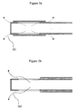
- a flow control device is shown in the fully closed condition, where water flow is minimised but not stopped. In this condition some water 301 flows between the tube and the sleeve. This flow allows the sleeve to be moved relative to the tube with low levels of force. Such flow acts to provide frictionless movement of the sleeve through hydraulically balanced water flow between the sleeve and the tube. Hydraulic balancing achieved, with respect to the central axis of a tube, is dependent upon the dimensioning and positioning of second openings of the tube.
- the flow control device is shown in an open condition in Figure 3B, where water flow 302 is approaching maximised.
- the flow control apparatus allows modulation of water flow from a low level to a higher level.
- Full shut-off of water flow may be effected by a separate water flow shut-off valve, which in some applications is operatively linked to the flow control device.
- the shut-off valve is provided upstream of the flow control apparatus.
- a manually operated shut-off valve may be provided.
- FIG. 4 shows a preferred water control apparatus.
- a water shut-off valve 401 is provided upstream of the water flow device 402 that is connected to the water flow device 402 by a rod 403 .
- the rod 403 is rigidly attached to the sleeve 405 by a pin 406 passing through second openings 407 of the tube 408 .
- the arrangement of the link is such that movement of the sleeve 405 causes the rod 403 to operate the shut-off valve 401.
- the rod 403 is held substantially centrally within the valve 401 by a frame structure 409, that provides axial stability, positions the rod 403 to allow it to move freely along the axis of the tube 408 and is configured to allow water to enter the valve 401.
- the shut-off valve 401 of Figure 4 is a two-stage operation valve.
- the rod 402 is fixed to a minor seal 410 that moves in unison with the sleeve 405.
- the minor seal 410 is shaped so as to act as a small, low area seal that acts on a major seal 411 .
- the major seal 411 floats axially on the rod 403 and is provided with at least one aperture 412.
- the major seal 411 is shaped to provide a larger seal within the tube 408.
- the minor seal 410 is shaped to close off the aperture(s) in the major seal 411 to provide a combined seal.
- a block 414 is fixed to the rod 403 between the major seal 411 and the pin 406, and is located to function as a control device for water flow through the valve 401.
- the block 414 pushes the major seal 411 away from the stop surface to allow water flow through the valve 401 .
- a gap is provided between block 414 and major seal 411 to allow movement of the minor seal 410 without moving the major seal 411 .
- the water control apparatus is configured such that when the valve 401 is closed, the sleeve 405 is in the fully closed condition and no water passes through the valve 401 or flow control device 402.
- FIG. 5A a two stage-operation valve, similar in construction to valve 401, is shown in the closed condition.
- the water acting against both the minor seal 503 and the larger seal 501 is sufficient to retain the seals in the shut position to prevent water flow through the valve.
- FIG. 5B A first stage of opening of the valve is shown in Figure 5B.
- the sleeve 502 of the water control apparatus is moved towards the valve and this causes the smaller seal 503 to open.
- the smaller seal 503 has a low surface area against the water and therefore a relatively small force is required to open the smaller seal 503 .
- Some water will flow through the gap between the tube 505 and the sleeve 502 .
- This flow will facilitate sleeve positioning through reducing resistance to sleeve movement, however, the leakage rate of this flow is sufficiently low to allow the tube 505 to fill with water flowing through the larger seal 504 .
- This flow of water into the tube 505 causes the water pressure on either side of the larger seal 501 to equalise, enabling the larger seal 501 to be thereafter opened with minimal force.
- FIG. 5C A second stage of opening of the valve is shown in Figure 5C.
- the tube 505 is filled with water
- further movement of the sleeve 502 into the open condition causes block 506 to push against the larger seal 501 .
- the larger seal 501 is lifted into the open position with force until water flows through the shut-off valve.
- Subsequent movement of the sleeve 502 into the open position exposes the second openings 507 of the tube 505, thereby increasing water flow through the flow control device.
- Sleeve positioning can then be effected to modulate the water flow through the water control device between low flow and high flow.
- the sleeve 502 is returned to the closed position. This action causes the smaller seal 503 to push against the larger seal 501 to close the gaps 504 in the larger seal 501 and to move the larger seal 501 towards the stop surface provided by 'O' ring 508.
- the water pressure causes both the larger seal 501 and the smaller seal 503 to close tightly, thereby shutting off water flow through the water control device.
- shut-off valve is such that a higher volume of water can flow through the valve with the smaller seal 503 open than through the gap between the tube 505 and the sleeve 502 of the water control apparatus.
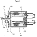
- a flow control device and shut-off valve can be embodied in a three port valve, as illustrated in Figure 6.
- two water control devices providing two ports, are positioned within a housing 601.
- one water control device receives hot water and the other receives cold water.
- Two water controllers 602, 603 are provided, one for each water control device, which are arranged to be independently controlled by individual reversible motors 604, 605 and co-operating gears 606, 607 respectively.
- the water controllers 602, 603 allow water entering the housing 601 to be mixed to a desired temperature.
- a third port 608 is provided.
- Positioning of a sleeve over its associated tube may be determined by a microprocessor, to provide desired output water temperature and/or flow rate, which may be defined by a user or stored in the microprocessor memory.
- Australian publication number AU 26307/92 describes use of a microprocessor.
- a thermistor, or mechanical thermostat, positioned downstream of a fluid mixing chamber may be provided, to produce signals for use in achieving and/or maintaining a desired fluid temperature.
- Figure 7 shows an embodiment in which two flow control devices 701, 702 are arranged parallel to each other within a water tight housing 703 having an exit port 704 .
- the tubes of the flow control devices 701, 702 are each provided with openings 705, 706 respectively, and the openings 705 , 706 are offset from each other, i.e. they are positionally staggered.
- the flow control devices 701, 702 are each provided with a sleeve 707, 708 respectively, and the two sleeves 707, 708 are joined together, in this example into a single sleeve block 709 .
- the position of the sleeve block 709 is variable, to vary the position of the sleeves 707, 708 relative to the tubes of the flow control devices 701, 702 respectively in unison, by means of operation of a lead screw 710 .
- the lead screw 710 enters the housing 703 through a seal 711 , and provides linear control.
- a crank drive may be used.
- a single motor is used to control the position of the sleeve block 709, which controls the relative flows of water through the flow control devices 701, 702 .
- This embodiment may be used in a domestic tap or shower application, in which one of the water control devices delivers hot water and the other cold water.
- the openings are not offset, however the sleeves are offset.
- the actual position of the sleeve block 709 may be determined by a microprocessor to provide mixed water of a desired output temperature, as defined by a user, or stored in the microprocessor memory.
- FIG. 7 provides control over mixed water temperature, but not flow rate.
- a full-shut off valve is not provided.
- the apparatus of Figure 7 may however be combined with an additional flow control valve, upstream.
- Such a valve may take the form of a manually operated gate valve, which can be arranged to provide control of water flow through water inlet ports and to provide full water flow shut-off.
- a user may be provided with both electronic and manual water control, for example, electronic temperature control and manual flow control.
- a visual user display may be provided to supply indications of water flow settings to a user.
- a controlling microprocessor may be used to initiate the sending of a signal to the pump to turn on, turn off, or to provide an intermediate condition.
- signals are transmitted via a wireless medium, for example by electromagnetic radiation.
- a three port valve may be operated from a power supply providing a peak power of less then 1000mW.
- a water control device as described may be used to control water flow through a heating system, for example in a radiator or under floor heating element.
Landscapes
- Engineering & Computer Science (AREA)
- General Engineering & Computer Science (AREA)
- Mechanical Engineering (AREA)
- Multiple-Way Valves (AREA)
- Sliding Valves (AREA)
- Flow Control (AREA)
- Electrically Driven Valve-Operating Means (AREA)
- Temperature-Responsive Valves (AREA)
- Magnetically Actuated Valves (AREA)
- Lift Valve (AREA)
Claims (12)
- Vorrichtung zum Regeln von Wasser, umfassend
ein wasserdichtes Gehäuse, das einen Auslass hat,
ein längliches Rohr (101), das in dem Gehäuse angeordnet ist,
eine erste Durchflussöffnung (102) an einem Ende des Rohres (101),
wenigstens eine zweite Durchflussöffnung (103) entlang der Länge des Rohres (101),
eine Hülse (104), die derart ausgebildet ist, dass sie während des wasserströmenden Zustandes entlang des Rohres (101) gleiten kann und
eine Vorrichtung zum Positionieren der Hülse für das Einstellen der Position der Hülse (104) und dadurch zum Regeln des Wasserdurchflusses,
wobei Wasser der ersten Durchflussöffnung (102) zugeführt wird und durch die zweite Durchflussöffnung (103) austritt,
dadurch gekennzeichnet, dass
zwischen dem Rohr (101) und der Hülse (104) ein Spalt vorhanden ist, um zu ermöglichen, dass etwas Wasser durch den Spalt (105) tritt, um die Hülse (104) von dem Rohr (101) abzulösen und um auch in einem vollständig geschlossenen Zustand etwas Durchfluss zu ermöglichen. - Vorrichtung nach Anspruch 1, wobei das Rohr (101) im Wesentlichen zylindrisch ist.
- Vorrichtung nach Anspruch 1 oder 2, wobei die Hülse (104) die Außenseite des Rohrs (101) umgreift.
- Vorrichtung nach einem der vorausgehenden Ansprüche, umfassend ein separates Absperrventil (401), das stromaufwärts von der Durchflussöffnung mit einem Zufluss verbunden ist.
- Vorrichtung nach Anspruch 4, wobei die Vorrichtung zum Positioniere der Hülse derart ausgebildet ist, dass sie beim Öffnen das Absperrventil (401) öffnet, bevor die Hülse (104) bewegt wird.
- Vorrichtung nach Anspruch 4 oder 5, wobei sie ferner ein Gestänge umfasst, das eine Verbindung zu dem Absperrventil (401) schafft, wobei sich das Gestänge durch das Rohr (408) erstreckt und mit der Hülse (405) verbunden ist, so dass das Bewegen der Hülse eine Bewegung des Gestänges verursacht, um das Absperrventil zu betätigen.
- Vorrichtung nach einem der Ansprüche 5 bis 7, wobei das Absperrventil (401) eine kleine Ventilkomponente (410) umfasst, um einen Druckausgleich zu ermöglichen, und eine große Ventilkomponente (411) umfasst, um einen Volumendurchfluss zu ermöglichen.
- Vorrichtung nach einem der Ansprüche 1 bis 7, wobei die Vorrichtung zum Positionieren der Hülse derart ausgebildet ist, dass sie mit einer zweiten Vorrichtung zum Positionieren einer Hülse einer ähnlichen zweiten Vorrichtung zusammenwirkt, so dass die zweite Vorrichtung zu einer Abnahme des Wasserdurchflusses führt, wenn durch die Vorrichtung der Wasserdurchfluss erhöht wird, und umgekehrt.
- Verfahren zum Regeln eines Wasserdurchflusses, umfassend folgende Schritte:Zuführen von Wasser zu einer ersten Durchflussöffnung (102) an einem Ende eines Rohres (101),Aufnehmen des Wassers von wenigstens einer zweiten Durchflussöffnung (103) entlang der Länge des Rohres (101) in ein Gehäuse, das einen Auslass hat, undPositionieren einer Hülse (104), die derart ausgebildet ist, dass sie während des wasserströmenden Zustandes entlang des Rohres (101) gleiten kann, und dadurch gekennzeichnet, dass
zwischen der Hülse (104) und dem Rohr (101) ein Spalt (105) vorhanden ist, um zu ermöglichen, dass etwas Wasser durch den Spalt (105) tritt, um die Hülse (104) von dem Rohr (101) abzulösen und um auch in einem vollständig geschlossenen Zustand etwas Durchfluss zu ermöglichen. - Verfahren nach Anspruch 9, umfassend den Schritt des Schließens des Wasserdurchflusses mittels eines separaten Absperrventils (401).
- Verfahren nach Anspruch 9 oder 10, in dem eine Vorrichtung zum Positionieren einer Hülse derart ausgebildet ist, dass sie Schritte durchführen kann, wenn ein Wasserdurchfluss ausgelöst wird, die umfassen:Öffnen einer kleinen Ventilkomponente (410), um einen Druckausgleich zu ermöglichen,Öffnen einer großen Ventilkomponente, um einen Volumendurchfluss einschließlich eines Flusses durch den Spalt (105) zu ermöglichen undEinstellen der Position der Hülse (104), um den Durchfluss von Wasser zu regeln.
- Verfahren nach einem der Ansprüche 9 bis 11, in dem heißes mit kaltem Wasser gemischt wird, um für Waschzwecke einen Fluss von warmen Wasser zu bewirken, umfassend folgende Schritte:Zuführen von heißem Wasser zu der ersten Durchflussöffnung (102) an einem Ende des Rohres (101),Aufnehmen des heißen Wassers von der wenigstens einen zweiten Durchflussöffnung (103) entlang der Länge des Rohres (101) in das Gehäuse,Zuführen von kaltem Wasser zu einer ersten Durchflussöffnung (102) an einem Ende eines zweiten Rohres (101),Aufnehmen des kalten Wassers von wenigstens einer zweiten Durchflussöffnung (103) entlang der Länge des zweiten Rohres (101) in das Gehäuse, wobei sich das aufgenommene heiße Wasser mit dem aufgenommenen kalten Wasser mischt, undPositionieren der Hülse (104), die derart ausgebildet ist, dass sie entlang des ersten Rohres (101) gleiten kann, in Kombination mit dem Positionieren einer zweiten Hülse (104), die derart ausgebildet ist, dass sie entlang des zweiten Rohres (101) gleiten kann, wobei zwischen jeder Hülse (104) und ihrem entsprechenden Rohr (101) ein Spalt (105) vorhanden ist, der ermöglicht, das etwas Wasser durch den Spalt (105) tritt, um jede Hülse (104) auch in einem vollständig geschlossenen Zustand von ihrem entsprechenden Rohr (101) abzuheben.
Applications Claiming Priority (4)
| Application Number | Priority Date | Filing Date | Title |
|---|---|---|---|
| GB0324020A GB0324020D0 (en) | 2003-10-14 | 2003-10-14 | Mixer valve using sliding cylinders to control flow |
| GB0324020 | 2003-10-14 | ||
| GB0405423 | 2004-03-11 | ||
| GB0405423A GB0405423D0 (en) | 2004-03-11 | 2004-03-11 | Sliding cylinder valve with modulation and shut off |
Publications (2)
| Publication Number | Publication Date |
|---|---|
| EP1526312A1 EP1526312A1 (de) | 2005-04-27 |
| EP1526312B1 true EP1526312B1 (de) | 2008-01-09 |
Family
ID=34395453
Family Applications (1)
| Application Number | Title | Priority Date | Filing Date |
|---|---|---|---|
| EP20040256301 Expired - Lifetime EP1526312B1 (de) | 2003-10-14 | 2004-10-13 | Ventil |
Country Status (5)
| Country | Link |
|---|---|
| US (1) | US7147203B2 (de) |
| EP (1) | EP1526312B1 (de) |
| AT (1) | ATE383535T1 (de) |
| DE (1) | DE602004011167T2 (de) |
| ES (1) | ES2299802T3 (de) |
Families Citing this family (12)
| Publication number | Priority date | Publication date | Assignee | Title |
|---|---|---|---|---|
| SE531995C2 (sv) * | 2008-07-10 | 2009-09-22 | Lindab Ab | Tryckfördelningslåda |
| US8167174B2 (en) | 2008-09-17 | 2012-05-01 | Harvey Elliott Berger | Inline fluid dispenser |
| WO2011115618A1 (en) * | 2010-03-16 | 2011-09-22 | Harvey Elliott Berger | Inline fluid dispenser |
| US8544628B2 (en) * | 2011-02-24 | 2013-10-01 | Ford Global Technologies, Llc | Pressure and flow continuity through transmission supports |
| US20130247995A1 (en) * | 2012-03-20 | 2013-09-26 | The Aerospace Corporation | Systems and Methods for a Control Valve |
| US9260843B2 (en) | 2012-06-22 | 2016-02-16 | Kohler Mira Limited | Valve disinfecting method |
| GB201220053D0 (en) * | 2012-11-07 | 2012-12-19 | Norgren Ltd C A | Motorized sleeve valve |
| CA2967225A1 (en) * | 2014-11-11 | 2016-05-19 | Chore-Time Europe B.V. | Flow control device for a convector heater |
| US10393281B2 (en) * | 2016-10-25 | 2019-08-27 | The Boeing Company | Compressor surge protection |
| GB2568271B (en) | 2017-11-09 | 2020-04-22 | Kohler Mira Ltd | A plumbing component for controlling the mixture of two supplies of water |
| US11079025B2 (en) * | 2018-03-07 | 2021-08-03 | Vortech Engineering, Inc. | Pressure relief valve apparatus, system and method |
| CN110873159A (zh) * | 2019-11-18 | 2020-03-10 | 上海海事大学 | 一种水下丝杠滑块传动装置 |
Family Cites Families (13)
| Publication number | Priority date | Publication date | Assignee | Title |
|---|---|---|---|---|
| DE512023C (de) | 1930-11-06 | Klein Schanzlin & Becker Akt G | Kolbenventil | |
| US2891761A (en) * | 1955-10-11 | 1959-06-23 | Controls Co Of America | Air prover |
| US3025880A (en) * | 1957-06-21 | 1962-03-20 | Borg Warner | Sleeve valves |
| US3874596A (en) * | 1974-02-11 | 1975-04-01 | Benjamin Baxter | Fluid dispensing device |
| US4540022A (en) * | 1982-06-01 | 1985-09-10 | Harry R. Cove | Choke for drilling or production use |
| US4508138A (en) * | 1983-08-05 | 1985-04-02 | Chas. M. Bailey Co., Inc. | Polyjet valve with backwash |
| US4796803A (en) * | 1985-03-18 | 1989-01-10 | Kelley Winfield L | Air volume regulator valve |
| US5024254A (en) | 1989-04-27 | 1991-06-18 | Hi-Sonic Co., Ltd. | Liquid shut-off valve |
| US4893655A (en) * | 1989-08-23 | 1990-01-16 | The United States Of America As Represented By The Secretary Of The Navy | Double valve mechanism for an acoustic modulator |
| US5072599A (en) * | 1991-03-13 | 1991-12-17 | Simone John J | Air tube control for frozen dessert machine |
| DE4213809C1 (de) | 1992-04-27 | 1993-07-22 | Bebro-Elektronik Bengel & Bross Gmbh, 7443 Frickenhausen, De | |
| JPH08145507A (ja) | 1994-11-24 | 1996-06-07 | Sanyo Electric Co Ltd | 冷媒流量制御弁及び冷媒流量制御弁を用いた冷凍装置 |
| US6929241B2 (en) * | 2001-01-25 | 2005-08-16 | Rufus M. Holloway, Jr. | Hydraulic valve and a liquid flow system |
-
2004
- 2004-10-13 DE DE200460011167 patent/DE602004011167T2/de not_active Expired - Lifetime
- 2004-10-13 US US10/964,558 patent/US7147203B2/en not_active Expired - Fee Related
- 2004-10-13 EP EP20040256301 patent/EP1526312B1/de not_active Expired - Lifetime
- 2004-10-13 AT AT04256301T patent/ATE383535T1/de not_active IP Right Cessation
- 2004-10-13 ES ES04256301T patent/ES2299802T3/es not_active Expired - Lifetime
Also Published As
| Publication number | Publication date |
|---|---|
| DE602004011167D1 (de) | 2008-02-21 |
| EP1526312A1 (de) | 2005-04-27 |
| DE602004011167T2 (de) | 2009-01-15 |
| ES2299802T3 (es) | 2008-06-01 |
| US20050155656A1 (en) | 2005-07-21 |
| US7147203B2 (en) | 2006-12-12 |
| ATE383535T1 (de) | 2008-01-15 |
Similar Documents
| Publication | Publication Date | Title |
|---|---|---|
| EP1526312B1 (de) | Ventil | |
| US12392119B2 (en) | Plumbing component | |
| US6290139B1 (en) | Hydraulically actuated mixing valve | |
| EP2824390B1 (de) | Gas-luftmischvorrichtung für verbrennungsvorrichtung | |
| US10443751B2 (en) | Valve with fail-safe device | |
| AU2003246412A1 (en) | Mixer valve | |
| CN108474486B (zh) | 热水混合水龙头用流体控制阀装置 | |
| JP7224761B2 (ja) | 流量制御装置及びそれを用いた温水器具 | |
| US5427312A (en) | Thermostatic mixing valve and method of use thereof | |
| EP2778485B1 (de) | Ventil | |
| JP2000179715A (ja) | ミキシングバルブ | |
| JP2001336646A (ja) | 湯水混合弁 | |
| JPH05165533A (ja) | 給湯装置 | |
| JP2669084B2 (ja) | 流体制御弁 | |
| CN222633896U (zh) | 一种泄压式恒温阀及恒温调节装置 | |
| CN220249102U (zh) | 一种可调温电磁混水阀 | |
| JP3258700B2 (ja) | 給湯装置の給湯温度調整装置 | |
| RU2339847C1 (ru) | Гидромеханическое устройство для плавной нагрузки гидравлической системы | |
| CN212616432U (zh) | 一种出水控制装置 | |
| WO2018121811A1 (de) | Regelarmatur zur regelung des differenzdruckes und/oder des volumenstromes | |
| GB2428285A (en) | Instantaneous water heater control | |
| JP7214410B2 (ja) | 流体制御装置 | |
| JP2002206810A (ja) | 自動給湯装置 | |
| JPH03199791A (ja) | 湯水混合装置 | |
| PL102484B1 (pl) | Flow control valve for two-component flux |
Legal Events
| Date | Code | Title | Description |
|---|---|---|---|
| PUAI | Public reference made under article 153(3) epc to a published international application that has entered the european phase |
Free format text: ORIGINAL CODE: 0009012 |
|
| AK | Designated contracting states |
Kind code of ref document: A1 Designated state(s): AT BE BG CH CY CZ DE DK EE ES FI FR GB GR HU IE IT LI LU MC NL PL PT RO SE SI SK TR |
|
| AX | Request for extension of the european patent |
Extension state: AL HR LT LV MK |
|
| 17P | Request for examination filed |
Effective date: 20051024 |
|
| AKX | Designation fees paid |
Designated state(s): AT BE BG CH CY CZ DE DK EE ES FI FR GB GR HU IE IT LI LU MC NL PL PT RO SE SI SK TR |
|
| 17Q | First examination report despatched |
Effective date: 20060912 |
|
| GRAP | Despatch of communication of intention to grant a patent |
Free format text: ORIGINAL CODE: EPIDOSNIGR1 |
|
| GRAS | Grant fee paid |
Free format text: ORIGINAL CODE: EPIDOSNIGR3 |
|
| GRAA | (expected) grant |
Free format text: ORIGINAL CODE: 0009210 |
|
| AK | Designated contracting states |
Kind code of ref document: B1 Designated state(s): AT BE BG CH CY CZ DE DK EE ES FI FR GB GR HU IE IT LI LU MC NL PL PT RO SE SI SK TR |
|
| REG | Reference to a national code |
Ref country code: GB Ref legal event code: FG4D |
|
| REG | Reference to a national code |
Ref country code: CH Ref legal event code: EP |
|
| REG | Reference to a national code |
Ref country code: IE Ref legal event code: FG4D |
|
| REF | Corresponds to: |
Ref document number: 602004011167 Country of ref document: DE Date of ref document: 20080221 Kind code of ref document: P |
|
| REG | Reference to a national code |
Ref country code: CH Ref legal event code: NV Representative=s name: MATHIEU NORTH DOCTEUR EN DROIT, AVOCAT |
|
| PG25 | Lapsed in a contracting state [announced via postgrant information from national office to epo] |
Ref country code: NL Free format text: LAPSE BECAUSE OF FAILURE TO SUBMIT A TRANSLATION OF THE DESCRIPTION OR TO PAY THE FEE WITHIN THE PRESCRIBED TIME-LIMIT Effective date: 20080109 Ref country code: SI Free format text: LAPSE BECAUSE OF FAILURE TO SUBMIT A TRANSLATION OF THE DESCRIPTION OR TO PAY THE FEE WITHIN THE PRESCRIBED TIME-LIMIT Effective date: 20080109 |
|
| REG | Reference to a national code |
Ref country code: ES Ref legal event code: FG2A Ref document number: 2299802 Country of ref document: ES Kind code of ref document: T3 |
|
| NLV1 | Nl: lapsed or annulled due to failure to fulfill the requirements of art. 29p and 29m of the patents act | ||
| PG25 | Lapsed in a contracting state [announced via postgrant information from national office to epo] |
Ref country code: FI Free format text: LAPSE BECAUSE OF FAILURE TO SUBMIT A TRANSLATION OF THE DESCRIPTION OR TO PAY THE FEE WITHIN THE PRESCRIBED TIME-LIMIT Effective date: 20080109 |
|
| ET | Fr: translation filed | ||
| PG25 | Lapsed in a contracting state [announced via postgrant information from national office to epo] |
Ref country code: BG Free format text: LAPSE BECAUSE OF FAILURE TO SUBMIT A TRANSLATION OF THE DESCRIPTION OR TO PAY THE FEE WITHIN THE PRESCRIBED TIME-LIMIT Effective date: 20080409 Ref country code: AT Free format text: LAPSE BECAUSE OF FAILURE TO SUBMIT A TRANSLATION OF THE DESCRIPTION OR TO PAY THE FEE WITHIN THE PRESCRIBED TIME-LIMIT Effective date: 20080109 |
|
| PG25 | Lapsed in a contracting state [announced via postgrant information from national office to epo] |
Ref country code: PL Free format text: LAPSE BECAUSE OF FAILURE TO SUBMIT A TRANSLATION OF THE DESCRIPTION OR TO PAY THE FEE WITHIN THE PRESCRIBED TIME-LIMIT Effective date: 20080109 Ref country code: PT Free format text: LAPSE BECAUSE OF FAILURE TO SUBMIT A TRANSLATION OF THE DESCRIPTION OR TO PAY THE FEE WITHIN THE PRESCRIBED TIME-LIMIT Effective date: 20080609 |
|
| PG25 | Lapsed in a contracting state [announced via postgrant information from national office to epo] |
Ref country code: DK Free format text: LAPSE BECAUSE OF FAILURE TO SUBMIT A TRANSLATION OF THE DESCRIPTION OR TO PAY THE FEE WITHIN THE PRESCRIBED TIME-LIMIT Effective date: 20080109 Ref country code: CZ Free format text: LAPSE BECAUSE OF FAILURE TO SUBMIT A TRANSLATION OF THE DESCRIPTION OR TO PAY THE FEE WITHIN THE PRESCRIBED TIME-LIMIT Effective date: 20080109 Ref country code: SK Free format text: LAPSE BECAUSE OF FAILURE TO SUBMIT A TRANSLATION OF THE DESCRIPTION OR TO PAY THE FEE WITHIN THE PRESCRIBED TIME-LIMIT Effective date: 20080109 Ref country code: SE Free format text: LAPSE BECAUSE OF FAILURE TO SUBMIT A TRANSLATION OF THE DESCRIPTION OR TO PAY THE FEE WITHIN THE PRESCRIBED TIME-LIMIT Effective date: 20080409 |
|
| PLBE | No opposition filed within time limit |
Free format text: ORIGINAL CODE: 0009261 |
|
| STAA | Information on the status of an ep patent application or granted ep patent |
Free format text: STATUS: NO OPPOSITION FILED WITHIN TIME LIMIT |
|
| PG25 | Lapsed in a contracting state [announced via postgrant information from national office to epo] |
Ref country code: RO Free format text: LAPSE BECAUSE OF FAILURE TO SUBMIT A TRANSLATION OF THE DESCRIPTION OR TO PAY THE FEE WITHIN THE PRESCRIBED TIME-LIMIT Effective date: 20080109 |
|
| 26N | No opposition filed |
Effective date: 20081010 |
|
| REG | Reference to a national code |
Ref country code: CH Ref legal event code: PCAR Free format text: MATHIEU NORTH, AVOCAT;RUE DE L'HOPITAL 22 CASE POSTALE 2751;2001 NEUCHATEL (CH) |
|
| PG25 | Lapsed in a contracting state [announced via postgrant information from national office to epo] |
Ref country code: EE Free format text: LAPSE BECAUSE OF FAILURE TO SUBMIT A TRANSLATION OF THE DESCRIPTION OR TO PAY THE FEE WITHIN THE PRESCRIBED TIME-LIMIT Effective date: 20080109 |
|
| PG25 | Lapsed in a contracting state [announced via postgrant information from national office to epo] |
Ref country code: MC Free format text: LAPSE BECAUSE OF NON-PAYMENT OF DUE FEES Effective date: 20081031 |
|
| PG25 | Lapsed in a contracting state [announced via postgrant information from national office to epo] |
Ref country code: CY Free format text: LAPSE BECAUSE OF FAILURE TO SUBMIT A TRANSLATION OF THE DESCRIPTION OR TO PAY THE FEE WITHIN THE PRESCRIBED TIME-LIMIT Effective date: 20080109 |
|
| PG25 | Lapsed in a contracting state [announced via postgrant information from national office to epo] |
Ref country code: IE Free format text: LAPSE BECAUSE OF NON-PAYMENT OF DUE FEES Effective date: 20081013 |
|
| PG25 | Lapsed in a contracting state [announced via postgrant information from national office to epo] |
Ref country code: LU Free format text: LAPSE BECAUSE OF NON-PAYMENT OF DUE FEES Effective date: 20081013 Ref country code: HU Free format text: LAPSE BECAUSE OF FAILURE TO SUBMIT A TRANSLATION OF THE DESCRIPTION OR TO PAY THE FEE WITHIN THE PRESCRIBED TIME-LIMIT Effective date: 20080710 |
|
| PG25 | Lapsed in a contracting state [announced via postgrant information from national office to epo] |
Ref country code: TR Free format text: LAPSE BECAUSE OF FAILURE TO SUBMIT A TRANSLATION OF THE DESCRIPTION OR TO PAY THE FEE WITHIN THE PRESCRIBED TIME-LIMIT Effective date: 20080109 |
|
| PG25 | Lapsed in a contracting state [announced via postgrant information from national office to epo] |
Ref country code: GR Free format text: LAPSE BECAUSE OF FAILURE TO SUBMIT A TRANSLATION OF THE DESCRIPTION OR TO PAY THE FEE WITHIN THE PRESCRIBED TIME-LIMIT Effective date: 20080410 |
|
| REG | Reference to a national code |
Ref country code: CH Ref legal event code: NV Representative=s name: CAROLE AUBERT AVOCATE |
|
| PGFP | Annual fee paid to national office [announced via postgrant information from national office to epo] |
Ref country code: CH Payment date: 20111011 Year of fee payment: 8 |
|
| PGFP | Annual fee paid to national office [announced via postgrant information from national office to epo] |
Ref country code: BE Payment date: 20121022 Year of fee payment: 9 |
|
| BERE | Be: lapsed |
Owner name: TERRELL, CHRISTOPHER Effective date: 20131031 |
|
| REG | Reference to a national code |
Ref country code: CH Ref legal event code: PL |
|
| PG25 | Lapsed in a contracting state [announced via postgrant information from national office to epo] |
Ref country code: CH Free format text: LAPSE BECAUSE OF NON-PAYMENT OF DUE FEES Effective date: 20131031 Ref country code: LI Free format text: LAPSE BECAUSE OF NON-PAYMENT OF DUE FEES Effective date: 20131031 |
|
| PG25 | Lapsed in a contracting state [announced via postgrant information from national office to epo] |
Ref country code: BE Free format text: LAPSE BECAUSE OF NON-PAYMENT OF DUE FEES Effective date: 20131031 |
|
| PGFP | Annual fee paid to national office [announced via postgrant information from national office to epo] |
Ref country code: FR Payment date: 20141008 Year of fee payment: 11 Ref country code: ES Payment date: 20141105 Year of fee payment: 11 |
|
| PGFP | Annual fee paid to national office [announced via postgrant information from national office to epo] |
Ref country code: IT Payment date: 20141022 Year of fee payment: 11 |
|
| PG25 | Lapsed in a contracting state [announced via postgrant information from national office to epo] |
Ref country code: IT Free format text: LAPSE BECAUSE OF NON-PAYMENT OF DUE FEES Effective date: 20151013 |
|
| REG | Reference to a national code |
Ref country code: FR Ref legal event code: ST Effective date: 20160630 |
|
| PG25 | Lapsed in a contracting state [announced via postgrant information from national office to epo] |
Ref country code: FR Free format text: LAPSE BECAUSE OF NON-PAYMENT OF DUE FEES Effective date: 20151102 |
|
| REG | Reference to a national code |
Ref country code: ES Ref legal event code: FD2A Effective date: 20161129 |
|
| PGFP | Annual fee paid to national office [announced via postgrant information from national office to epo] |
Ref country code: DE Payment date: 20161011 Year of fee payment: 13 |
|
| PG25 | Lapsed in a contracting state [announced via postgrant information from national office to epo] |
Ref country code: ES Free format text: LAPSE BECAUSE OF NON-PAYMENT OF DUE FEES Effective date: 20151014 |
|
| REG | Reference to a national code |
Ref country code: DE Ref legal event code: R119 Ref document number: 602004011167 Country of ref document: DE |
|
| PG25 | Lapsed in a contracting state [announced via postgrant information from national office to epo] |
Ref country code: DE Free format text: LAPSE BECAUSE OF NON-PAYMENT OF DUE FEES Effective date: 20180501 |
|
| PGFP | Annual fee paid to national office [announced via postgrant information from national office to epo] |
Ref country code: GB Payment date: 20180925 Year of fee payment: 15 |
|
| GBPC | Gb: european patent ceased through non-payment of renewal fee |
Effective date: 20191013 |
|
| PG25 | Lapsed in a contracting state [announced via postgrant information from national office to epo] |
Ref country code: GB Free format text: LAPSE BECAUSE OF NON-PAYMENT OF DUE FEES Effective date: 20191013 |