EP1526289A2 - Ventil für Fluidsystem - Google Patents
Ventil für Fluidsystem Download PDFInfo
- Publication number
- EP1526289A2 EP1526289A2 EP04022742A EP04022742A EP1526289A2 EP 1526289 A2 EP1526289 A2 EP 1526289A2 EP 04022742 A EP04022742 A EP 04022742A EP 04022742 A EP04022742 A EP 04022742A EP 1526289 A2 EP1526289 A2 EP 1526289A2
- Authority
- EP
- European Patent Office
- Prior art keywords
- valve
- fluid
- working
- connections
- valve according
- Prior art date
- Legal status (The legal status is an assumption and is not a legal conclusion. Google has not performed a legal analysis and makes no representation as to the accuracy of the status listed.)
- Granted
Links
Images


Classifications
-
- F—MECHANICAL ENGINEERING; LIGHTING; HEATING; WEAPONS; BLASTING
- F15—FLUID-PRESSURE ACTUATORS; HYDRAULICS OR PNEUMATICS IN GENERAL
- F15B—SYSTEMS ACTING BY MEANS OF FLUIDS IN GENERAL; FLUID-PRESSURE ACTUATORS, e.g. SERVOMOTORS; DETAILS OF FLUID-PRESSURE SYSTEMS, NOT OTHERWISE PROVIDED FOR
- F15B13/00—Details of servomotor systems ; Valves for servomotor systems
- F15B13/02—Fluid distribution or supply devices characterised by their adaptation to the control of servomotors
- F15B13/06—Fluid distribution or supply devices characterised by their adaptation to the control of servomotors for use with two or more servomotors
-
- F—MECHANICAL ENGINEERING; LIGHTING; HEATING; WEAPONS; BLASTING
- F15—FLUID-PRESSURE ACTUATORS; HYDRAULICS OR PNEUMATICS IN GENERAL
- F15B—SYSTEMS ACTING BY MEANS OF FLUIDS IN GENERAL; FLUID-PRESSURE ACTUATORS, e.g. SERVOMOTORS; DETAILS OF FLUID-PRESSURE SYSTEMS, NOT OTHERWISE PROVIDED FOR
- F15B13/00—Details of servomotor systems ; Valves for servomotor systems
- F15B13/02—Fluid distribution or supply devices characterised by their adaptation to the control of servomotors
- F15B13/04—Fluid distribution or supply devices characterised by their adaptation to the control of servomotors for use with a single servomotor
- F15B13/0401—Valve members; Fluid interconnections therefor
- F15B13/0402—Valve members; Fluid interconnections therefor for linearly sliding valves, e.g. spool valves
-
- F—MECHANICAL ENGINEERING; LIGHTING; HEATING; WEAPONS; BLASTING
- F16—ENGINEERING ELEMENTS AND UNITS; GENERAL MEASURES FOR PRODUCING AND MAINTAINING EFFECTIVE FUNCTIONING OF MACHINES OR INSTALLATIONS; THERMAL INSULATION IN GENERAL
- F16K—VALVES; TAPS; COCKS; ACTUATING-FLOATS; DEVICES FOR VENTING OR AERATING
- F16K27/00—Construction of housing; Use of materials therefor
- F16K27/04—Construction of housing; Use of materials therefor of sliding valves
- F16K27/041—Construction of housing; Use of materials therefor of sliding valves cylindrical slide valves
-
- F—MECHANICAL ENGINEERING; LIGHTING; HEATING; WEAPONS; BLASTING
- F16—ENGINEERING ELEMENTS AND UNITS; GENERAL MEASURES FOR PRODUCING AND MAINTAINING EFFECTIVE FUNCTIONING OF MACHINES OR INSTALLATIONS; THERMAL INSULATION IN GENERAL
- F16K—VALVES; TAPS; COCKS; ACTUATING-FLOATS; DEVICES FOR VENTING OR AERATING
- F16K27/00—Construction of housing; Use of materials therefor
- F16K27/04—Construction of housing; Use of materials therefor of sliding valves
- F16K27/048—Electromagnetically actuated valves
Definitions
- the present invention relates to a valve for Fluid systems according to the preamble of claim 1.
- Fluid controls and / or fluid controls require for the Realization of their functions corresponding adjusting elements.
- control elements are, for example, rule or Switching valves.
- the medium is used to drive the actuators, e.g. Cylinder or engines subjected to high pressure.
- the actuators e.g. Cylinder or engines subjected to high pressure.
- pumps are used, which for the Pilot oil flow a pressure of 30 bar and a Reach output of 10 1 per minute, and for the Main oil flow a pressure of 300 bar and a capacity from 100 1 per minute.
- the first disadvantage is that the affected actuator a Performing work movement that is not desired and thus a corresponding potential for harm and danger brings.
- the second disadvantage is the problem that the Actuators for such a one-sided pressurization not are designed. That the mechanical components are over their permissible limits are also subjected to pressure, so that This can cause damage to them. So can for example, in a double-acting cylinder the Cylinder housing to be damaged by the excessive pressure. Corresponding damage can of course also at Hydraulic motors and other components of the hydraulic system occur.
- the object of the present invention is therefore, a Further develop valve for fluid systems so that the above minimized or even eliminated.
- a valve according to the invention is characterized for fluid systems, especially for hydraulic systems, with two first working connections C, D for the inflow and outflow of the Fluids to a first fluid-actuated device and two second working connections E, F for inflow and outflow the fluid to a second fluid actuatable device, and two supply terminals A, B for the supply side and outflow of the fluid thereby, a fluid-conducting short-circuit connection between the in the respective switching position not with the Supply terminals A, B connected working ports C, D or E, F is present.
- valve cartridge in a preferred embodiment it can be provided in that one provided with fluid-conducting connecting elements, suitable for use in a housing valve cartridge is available.
- the advantage of such an embodiment can For example, it is that such a cartridge can be replaced at any time against another cartridge, without that it is necessary to replace the entire valve.
- the reason for changing the valve cartridge can be be diverse nature. Be it that the valve cartridge itself, or components subject to wear the Valve cartridge no longer work properly, or that a modified function of the valve is desired.
- the Cause of the change request is secondary, is essential that by simply replacing the valve cartridge inside shortest time the valve in the desired mode of operation is available again.
- valve cartridge in a further embodiment, it may, for example be provided that one with fluid-conducting Fastener provided housing with a receptacle is provided for the valve cartridge.
- a housing can advantageously valve cartridges in different Embodiments are used so that thereby possibly application-dependent changed functions are feasible.
- valve cartridge comprises a displaceable plunger. This results, for example, a very compact Construction for such a valve.
- the plunger with fluid-conducting fasteners is provided.
- These connecting elements may e.g.
- Holes, grooves, punctures and the like may be more.
- By moving the plunger in the cartridge can For example, realized switching and / or control functions become.
- By training this fluid-conducting Connecting elements in or on the plunger for example a further minimization of space requirements and / or a simple Manufacture of the valve can be achieved.
- the valve is designed as a 6/2-way valve.
- 6/2-way valve has the advantage that it is in Control or rule case directly from a work unit or their direction of movement to the other unit of work or whose direction of motion can switch, with very little Delay times between the two switching states can be achieved.
- valve as a 6/3-way valve is trained.
- Such a 6/3-way valve has the advantage that the first through-working connections longer disconnected from the supply connections and thus are switched off until the second souzugateden Working connections are fluid-conducting through, as this for example, in contrast, the faster switching on the other hand 6/2-way valve embodiment is the case.
- an additional Security Reserve to be achieved so that the previously controlled device or its movement in any case comes to a halt before the next device or whose movement is activated.
- This embodiment offers the advantage of being in one Can be put in a state in which none of Working connections is switched through fluid-conducting.
- These are optionally different embodiments conceivable.
- a first simple embodiment may be provided be that in this switch position all connections, so the both first and second working ports C, D and E, F as well as the supply connections A, B all only are individually closed.
- a magnetic coil is available for the actuation of the valve.
- a magnetic coil By the arrangement of a magnetic coil, the For example, working against a spring, it is possible that Electrically adjust the valve against the force of the spring.
- the magnetic coil as a two-way solenoid is trained.
- This can, for example, a 6/3-way valve can be realized, which by means of spring force is held in the neutral position and depending on the control the solenoid coil the first and second working ports C, D and E, F with the supply ports A, B fluid-conducting turns on.
- a spring for the return of the valve is.
- This spring can, for example, the provision of the Valves effect when the valve is either as above described via a solenoid is activated, or if For example, it is adjusted via a fluid.
- the fluid is then also a hydraulic oil, it But it is also possible, a gaseous medium for to provide the drive.
- the spring causes the return as soon as the on Valve acting force is less than the spring force.
- valve as part of a multi-valve connectable valve block is formed.
- valves or even valve groups to a larger one Switching and / or control unit are interconnected.
- switching and / or Control loops in block form possible. If necessary, you can Such blocks in turn make sense according to their functions further integrated together in a control and / or regulation become.
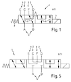
- FIG. 1 shows a circuit diagram symbol for a 6/2-way valve in FIG the embodiment of the invention. These are in the left Switch block the connections C and D of the working connection 2 and in the right switch block the connections E and F of the Work connection 3 provided with short-circuit connections 5. These short-circuit connections ensure that at Break in a leakage oil flow to one of the two ports C or D or E or F of each not through-connected Working connection also necessarily the second connection with the equal oil pressure is applied. This will achieve that both the supply and the return of the affected working port with the same oil pressure be charged. As actuators are a coil. 7 and a spring 8 shown symbolically.
- the left or the right in the illustrated embodiment is the Switching through the pumped by the pump oil flow over the supply connection A to the work connection E or C and the return line via the working port F or D to the Tank connection B realized.
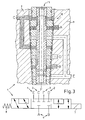
- FIG. 2 shows a circuit diagram symbol for a 6/3-way valve according to the invention and a representation of fluid conducting connections in a valve according to the shown switching position from the schematic diagram.
- the symbol block of the circuit diagram symbol is the working connection 3 for the valve 1 via the switching connections 6 with the Supply connection 4 connected.
- the short-circuit connection 5 formed for the work connection 2 between terminals C and D.
- Fluid-conducting connections symbolize the partial Structure of a valve according to the invention with a housing 9 in which a cartridge 10 is arranged.
- 9 is a part of the short-circuit connection 5 between the Terminal C and the terminal D formed.
- Another Part of this short-circuit connection 5 between the terminals C and D of the working port 2 is in the cartridge 10 educated.
- This part of the short-circuit connection 5 is for Part as a puncture in the outer contour of the cartridge and partly designed as a bore.
- a plunger 11 is arranged inside the cartridge 10. This plunger 11 also has parts of the short-circuit connection 5 on, between the terminal C and the Connection D realized in this switching position of the valve 1 is.
- the switching connection 6 between the terminal A of Supply connection 4 and the connection E of Working connection 3 is also over all three units, Housing 9, cartridge 10 and plunger 11 is distributed.
- the second switching connection 6 from the tank connection, so the Terminal B of the supply terminal 4 to the terminal F of Working connection 3, is also about all three units, Housing 9, cartridge 10 and plunger 11, formed.
- the plunger has an axial in this embodiment trained, through hole on the front side with connected to the terminal F. Connected to this are two axially spaced, radially aligned Cross holes, depending on the switch position part of Switching connection 6 and the short-circuit connection 5 are.
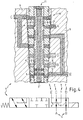
- FIG. 3 again shows the circuit diagram symbol for the Valve 1 and arranged above the fluid-conducting Compounds in a valve exemplified with Valve cartridge 10 and disposed therein plunger 11.
- the plunger against the view in Figure 2 moved axially downwards, leaving no connections between the individual connections of the working and Supply connections 2 to 4 more exist. That is, it is So is neither one of the working ports 2, 3 with the Supply connection 4 connected via switching connections 6, still exist short-circuit connections 5 between the individual terminals C and D or E and F of Working lines. In the schematic diagram this is indicated by the corresponding line terminations in the middle switching block shown.
- FIG. 4 is the complementary one Switching diagram for illustration in Figure 2. This applies for both the schematic and the representation the fluid-conducting connections in the embodiment of the valve 1.
- the schematic diagram the right of the three Symbol blocks with the two working ports 2, 3 and the Supply connection 4 connected. This switching state of course reflected in the above Embodiment again.
- the Plunger 11 By further shifting the Plunger 11 in the axial direction down towards the Representations in Figures 2 and 3 are the compounds A-C and D-B connected by means of the switching connection 6. Again these connections are over all three Elements of the valve 1, so the housing 9, the cartridge 10th and the plunger 11 is formed.
- the short circuit connection is correspondingly shown between the terminals E and F.
- FIG. 5 shows a further circuit diagram symbol for a possible embodiment of a 6/3-way valve.
- the terminals C and D of Working connection 2 and the connections E and F of Working connection 3 in the neutral switching state of the valve. 1 each by short-circuit connections 5 with each other connected.
- the connections A and B of the supply connection 4 are shown separated from each other.
- FIG 6 is an exemplary representation of a Hydraulic circuit diagram with pilot and main oil circuit shown in which a valve according to the invention for Fluid systems used in the form of a 6/2-way valve is.
- the valve 1 is located in the pilot oil circuit and operated, depending on the switching position of the two Main control valves 13 and 14 in the main oil circuit.
- Of the Pilot oil flow is supplied from the oil supply pump 17 generated.
- Pressure for example, in this circuit Pressure of 30 bar at a capacity of 10 1 per Minute.
- the main control valves 13 and 14 for the two working cylinders 15 and 16 driven. in the Main oil flow prevails, for example, a pressure of 300 bar at a supply capacity of 100 1 per minute.
- the two main oil circuits from the respective Oil supplies 18.
- the direction of the oil flowing through in the pilot control circuit is specified by means of the pilot control device 12. Depending on in which control position the pilot control device is activated, the pilot oil flow flows straight or crossed Flow direction through the pilot control device 12 and acts according to the same time through the valve 1 controlled main control valve 13 and 14. Accordingly is the relevant working cylinder 15 or 16 through the respective main control valve 13 or 14 extending or retracting driven.
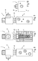
- Figure 7 shows a sectional view a valve 1 according to the invention with the housing 9, the disposed therein cartridge 10 and in the cartridge arranged plunger 11. It is placed on the electromagnetic structure 19 with its corresponding mechanical connecting elements 20 shown.
- FIGs 8 and 9 each show a side view of the Valves 1 of Figure 7 with the visible from the outside housing 9, the electromagnetic structure 19 and its mechanical Connecting elements 20.
- FIG. 10 shows a bottom view of the valve 1 according to FIG Figure 7.
- the housing 9 in a rectangular plan recognizable, centrally in its center the connection F of Häan gleiche 3 and at the top of a part of electromagnetic structure 19.
Landscapes
- Engineering & Computer Science (AREA)
- General Engineering & Computer Science (AREA)
- Mechanical Engineering (AREA)
- Physics & Mathematics (AREA)
- Fluid Mechanics (AREA)
- Electromagnetism (AREA)
- Multiple-Way Valves (AREA)
- Fluid-Driven Valves (AREA)
- Fluid-Pressure Circuits (AREA)
- Magnetically Actuated Valves (AREA)
Abstract
Description
- Figur 1
- Das Schaltbildsymbol eines erfindungsgemäßen 6/2-Wegeventils,
- Figuren 2 bis 4
- die Schaltbildsymbole eines 6/3-Wegeventiles, jeweils zusammen mit einem möglichen Ausführungsbeispiel anhand dargestellter leitender und nicht leitender Schaltverbindungen,
- Figur 5
- ein Schaltbildsymbol für eine weitere Ausführungsform eines erfindungsgemäßen 6/3-Wegeventiles,
- Figur 6
- einen beispielhaften Schaltplan, in dem ein erfindungsgemäßes 6/2-Wegeventil im Stromkreis des Vorsteuerölstroms angeordnet ist,
- Figur 7
- einen Schnitt durch einen beispielhaften Aufbau eines erfindungsgemäßen Ventiles,
- Figuren 8 und 9
- jeweilige Seitenansichten zu einem Ventil entsprechend der Figur 7 und
- Figur 10
- eine Unteransicht auf das Ventil nach Figur 7.
- 1
- Ventil
- 2
- Arbeitsanschluss
- 3
- Arbeitsanschluss
- 4
- Versorgungsanschluss
- 5
- Kurzschluss-Verbindung
- 6
- Schaltverbindung
- 7
- Spule
- 8
- Feder
- 9
- Gehäuse
- 10
- Patrone
- 11
- Stößel
- 12
- Vorsteuergerät
- 13
- Hauptsteuerventil
- 14
- Hauptsteuerventil
- 15
- Arbeitszylinder
- 16
- Arbeitszylinder
- 17
- Ölversorgung
- 18
- Ölversorgung
- 19
- Elektromagnetischer Aufbau
- 20
- Mechanische Verbindungselemente
Claims (15)
- Ventil für Fluidsysteme, insbesondere für Hydrauliksysteme, mit zwei ersten Arbeitsanschlüssen (C, D) für den Zu- und Abfluss des Fluids zu einer ersten, fluidbetätigbaren Vorrichtung, und zwei zweiten Arbeitsanschlüssen (E, F) für den Zu- und Abfluss des Fluids zu einer zweiten fluidbetätigbaren Vorrichtung, und zwei Versorgungsanschlüssen (A, B) für den versorgungsseitigen Zuund Abfluss des Fluids, dadurch gekennzeichnet, dass eine fluidleitende Kurzschluss-Verbindung zwischen den in der jeweiligen Schaltstellung nicht mit den Versorgungsanschlüssen (A, B) verbundenen Arbeitsanschlüssen (C und D bzw. E und F) vorhanden ist.
- Ventil nach Anspruch 1, dadurch gekennzeichnet, dass eine mit fluidleitenden Verbindungselementen versehene, für den Einsatz in einem Gehäuse geeignete Ventilpatrone vorhanden ist.
- Ventil nach einem der vorhergehenden Ansprüche, dadurch gekennzeichnet, dass ein mit fluidleitenden Verbindungselementen versehenes Gehäuse mit einer Aufnahme für die Ventilpatrone vorgesehen ist.
- Ventil nach einem der vorhergehenden Ansprüche, dadurch gekennzeichnet, dass die Ventilpatrone einen verschiebbaren Stößel umfasst.
- Ventil nach einem der vorhergehenden Ansprüche, dadurch gekennzeichnet, dass der Stößel mit fluidleitenden Verbindungselementen versehen ist.
- Ventil nach einem der vorhergehenden Ansprüche, dadurch gekennzeichnet, dass wenigstens ein Teil der Kurzschluss-Verbindung für die Arbeitsanschlüsse (C, D) bzw. (E, F) im Gehäuse für die Aufnahme der Ventilpatrone angeordnet ist.
- Ventil nach einem der vorhergehenden Ansprüche, dadurch gekennzeichnet, dass wenigstens ein Teil der Kurzschluss-Verbindung für die Arbeitsanschlüsse (C, D) bzw. (E, F) in der Ventilpatrone angeordnet ist.
- Ventil nach einem der vorhergehenden Ansprüche, dadurch gekennzeichnet, dass wenigstens ein Teil der Kurzschluss-Verbindung für die Arbeitsanschlüsse (C, D) bzw. (E, F) im Stößel angeordnet ist.
- Ventil nach einem der vorhergehenden Ansprüche, dadurch gekennzeichnet, dass das Ventil als 6/2-Wegeventil ausgebildet ist.
- Ventil nach einem der Ansprüche 1 bis 8, dadurch gekennzeichnet, dass das Ventil als 6/3-Wegeventil ausgebildet ist.
- Ventil nach Anspruch 10, dadurch gekennzeichnet, dass eine neutrale Schaltstellung für das Ventil ausgebildet ist, in der weder die ersten Arbeitsanschlüsse (E, F) noch die zweiten Arbeitsanschlüsse (C, D) mit den Versorgungsanschlüssen (A, B) durchgeschaltet sind.
- Ventil nach einem der vorhergehenden Ansprüche, dadurch gekennzeichnet, dass für die Betätigung des Ventils eine Magnetspule vorhanden ist.
- Ventil nach Anspruch 12, dadurch gekennzeichnet, dass die Magnetspule als Zweiwege-Magnetspule ausgebildet ist.
- Ventil nach einem der vorhergehenden Ansprüche, dadurch gekennzeichnet, dass für die Rückstellung des Ventils eine Feder vorhanden ist.
- Ventil nach einem der vorhergehenden Ansprüche, dadurch gekennzeichnet, dass das Ventil als Teil eines mit mehreren Ventilen verbindbarem Ventilblockes ausgebildet ist.
Applications Claiming Priority (2)
| Application Number | Priority Date | Filing Date | Title |
|---|---|---|---|
| DE10349228 | 2003-10-23 | ||
| DE10349228A DE10349228A1 (de) | 2003-10-23 | 2003-10-23 | Ventil für Fluidsystem |
Publications (3)
| Publication Number | Publication Date |
|---|---|
| EP1526289A2 true EP1526289A2 (de) | 2005-04-27 |
| EP1526289A3 EP1526289A3 (de) | 2005-07-27 |
| EP1526289B1 EP1526289B1 (de) | 2006-09-06 |
Family
ID=34384407
Family Applications (1)
| Application Number | Title | Priority Date | Filing Date |
|---|---|---|---|
| EP04022742A Expired - Lifetime EP1526289B1 (de) | 2003-10-23 | 2004-09-24 | Ventil für Fluidsystem |
Country Status (3)
| Country | Link |
|---|---|
| EP (1) | EP1526289B1 (de) |
| AT (1) | ATE338889T1 (de) |
| DE (2) | DE10349228A1 (de) |
Cited By (3)
| Publication number | Priority date | Publication date | Assignee | Title |
|---|---|---|---|---|
| WO2010141621A1 (en) * | 2009-06-02 | 2010-12-09 | Eaton Corporation | Hydraulic system |
| US8356630B2 (en) | 2008-06-02 | 2013-01-22 | Eaton Corporation | Valve damping system |
| DE102022118889A1 (de) | 2022-07-27 | 2024-02-01 | Liebherr-Aerospace Lindenberg Gmbh | Ventil und Luftfahrzeug |
Family Cites Families (8)
| Publication number | Priority date | Publication date | Assignee | Title |
|---|---|---|---|---|
| BE528346A (de) * | ||||
| US3015344A (en) * | 1958-05-24 | 1962-01-02 | Schlepperwerk Nordhausen Veb | Hydraulic control valve |
| FR1227434A (fr) * | 1959-03-06 | 1960-08-19 | Rech Etudes Production Sarl | Dispositif pour la commande hydraulique à distance de récepteurs indépendants à fonctionnement simultané |
| DE3110210A1 (de) * | 1981-03-17 | 1982-09-30 | Hartmann & Lämmle GmbH & Co KG, 7255 Rutesheim | Hydraulische schalteinrichtung zur steuerung der arbeits- und stillstandsphasen von arbeits- oder werkzeugmaschinen |
| DE3639174C2 (de) * | 1986-11-15 | 1998-02-05 | Bosch Gmbh Robert | Hydraulische Steuereinrichtung |
| DE19633191C2 (de) * | 1996-08-17 | 1998-07-02 | Daimler Benz Ag | Umschaltventil für ein Druckmedium |
| DE19723219A1 (de) * | 1997-06-03 | 1998-12-10 | Frutigen Hydrotechnik Ag | Hydraulisches Mehrwegeventil, insbesondere Lenkartenwählventil für mehrachsig gelenkte Fahrzeuge |
| DE10223717A1 (de) * | 2002-05-28 | 2003-12-11 | Linde Ag | Hydrostatisches Antriebssystem |
-
2003
- 2003-10-23 DE DE10349228A patent/DE10349228A1/de not_active Withdrawn
-
2004
- 2004-09-24 EP EP04022742A patent/EP1526289B1/de not_active Expired - Lifetime
- 2004-09-24 DE DE502004001399T patent/DE502004001399D1/de not_active Expired - Lifetime
- 2004-09-24 AT AT04022742T patent/ATE338889T1/de active
Cited By (11)
| Publication number | Priority date | Publication date | Assignee | Title |
|---|---|---|---|---|
| US8302627B2 (en) | 2008-06-02 | 2012-11-06 | Eaton Corporation | Hydraulic system |
| US8356630B2 (en) | 2008-06-02 | 2013-01-22 | Eaton Corporation | Valve damping system |
| US8464754B2 (en) | 2008-06-02 | 2013-06-18 | Eaton Corporation | Valve manifold |
| US8590570B2 (en) | 2008-06-02 | 2013-11-26 | Eaton Corporation | Two step valve actuator |
| US8646481B2 (en) | 2008-06-02 | 2014-02-11 | Eaton Corporation | Valve having integrated pressure assist mechanism |
| US9435438B2 (en) | 2008-06-02 | 2016-09-06 | Eaton Corporation | Valve manifold |
| WO2010141621A1 (en) * | 2009-06-02 | 2010-12-09 | Eaton Corporation | Hydraulic system |
| CN102459920A (zh) * | 2009-06-02 | 2012-05-16 | 伊顿公司 | 液压系统 |
| CN102459920B (zh) * | 2009-06-02 | 2015-07-15 | 伊顿公司 | 液压系统 |
| DE102022118889A1 (de) | 2022-07-27 | 2024-02-01 | Liebherr-Aerospace Lindenberg Gmbh | Ventil und Luftfahrzeug |
| US12480534B2 (en) | 2022-07-27 | 2025-11-25 | Liebherr-Aerospace Lindenberg Gmbh | Valve and aircraft |
Also Published As
| Publication number | Publication date |
|---|---|
| DE10349228A1 (de) | 2005-05-19 |
| EP1526289B1 (de) | 2006-09-06 |
| EP1526289A3 (de) | 2005-07-27 |
| ATE338889T1 (de) | 2006-09-15 |
| DE502004001399D1 (de) | 2006-10-19 |
Similar Documents
| Publication | Publication Date | Title |
|---|---|---|
| EP0818629B1 (de) | Hydraulische Stelleinheit und Verfahren zum Entlüften einer hydraulischen Stelleinheit | |
| EP0850151B1 (de) | Einrichtung zur rollstabilisierung eines fahrzeugs | |
| EP2960561B1 (de) | Hydraulikventil | |
| EP2234135B1 (de) | Ventilanordnung | |
| DE69704045T2 (de) | Steuerventilverteilerplatte mit innerer oder äusserer Steuerschaltung | |
| DE3347000C2 (de) | ||
| EP0854982A2 (de) | Ventilsystem | |
| EP2488764A1 (de) | Ventilanordnung | |
| EP2855946B1 (de) | Ventil für ventilanordnung | |
| DE102007054137A1 (de) | Hydraulische Ventilvorrichtung | |
| EP3990789B1 (de) | Hydraulik-steuerblock und hydraulische achse mit dem steuerblock | |
| EP0641919B1 (de) | Hydraulische Sicherheitsschaltung | |
| EP2647883B1 (de) | Hydraulische Steuerungsvorrichtung | |
| WO2014056592A1 (de) | Open-center-ventilblock mit zwei pumpenanschlüssen und zugeordneten hilfsschiebern an den hauptschiebern | |
| WO2010112130A1 (de) | Hydromechanischer antrieb für elektrische leistungsschalter | |
| EP1526289B1 (de) | Ventil für Fluidsystem | |
| EP2220378B1 (de) | Hydraulische ventilvorrichtung | |
| EP2163770B1 (de) | Interner Lastdruckabgriff für ein Mehrwege-Mehrstellungs-Schieberventil | |
| EP2360380B1 (de) | Hydraulisches Steuerventil für einen einseitig arbeitenden Differentialzylinder mit fünf Steuerkanten | |
| DE102016216264A1 (de) | Fluidanordnung zum Betätigen von Fahrzeugkomponenten | |
| DE102009034286B3 (de) | Hydraulische Schaltungsanordnung zum Steuern eines doppelt wirkenden Arbeitszylinders mittels eine fünf Anschlüsse aufweisenden Steuerventils | |
| DE3519148C2 (de) | ||
| EP2452078A1 (de) | Anordnung zur bereitstellung eines veränderbaren drosselquerschnitts für einen fluidstrom | |
| DE19613848C2 (de) | Sicherheitsschaltung zum Ansteuern eines hydraulischen Antriebes | |
| DE102012218271A1 (de) | Hydraulische Steuerung für reversierbare hydraulische Verbraucher |
Legal Events
| Date | Code | Title | Description |
|---|---|---|---|
| PUAI | Public reference made under article 153(3) epc to a published international application that has entered the european phase |
Free format text: ORIGINAL CODE: 0009012 |
|
| AK | Designated contracting states |
Kind code of ref document: A2 Designated state(s): AT BE BG CH CY CZ DE DK EE ES FI FR GB GR HU IE IT LI LU MC NL PL PT RO SE SI SK TR |
|
| AX | Request for extension of the european patent |
Extension state: AL HR LT LV MK |
|
| PUAL | Search report despatched |
Free format text: ORIGINAL CODE: 0009013 |
|
| AK | Designated contracting states |
Kind code of ref document: A3 Designated state(s): AT BE BG CH CY CZ DE DK EE ES FI FR GB GR HU IE IT LI LU MC NL PL PT RO SE SI SK TR |
|
| AX | Request for extension of the european patent |
Extension state: AL HR LT LV MK |
|
| RIC1 | Information provided on ipc code assigned before grant |
Ipc: 7F 15B 13/06 B Ipc: 7F 15B 13/04 A |
|
| 17P | Request for examination filed |
Effective date: 20051027 |
|
| AKX | Designation fees paid |
Designated state(s): AT BE BG CH CY CZ DE DK EE ES FI FR GB GR HU IE IT LI LU MC NL PL PT RO SE SI SK TR |
|
| GRAP | Despatch of communication of intention to grant a patent |
Free format text: ORIGINAL CODE: EPIDOSNIGR1 |
|
| GRAS | Grant fee paid |
Free format text: ORIGINAL CODE: EPIDOSNIGR3 |
|
| GRAA | (expected) grant |
Free format text: ORIGINAL CODE: 0009210 |
|
| AK | Designated contracting states |
Kind code of ref document: B1 Designated state(s): AT BE BG CH CY CZ DE DK EE ES FI FR GB GR HU IE IT LI LU MC NL PL PT RO SE SI SK TR |
|
| PG25 | Lapsed in a contracting state [announced via postgrant information from national office to epo] |
Ref country code: IE Free format text: LAPSE BECAUSE OF FAILURE TO SUBMIT A TRANSLATION OF THE DESCRIPTION OR TO PAY THE FEE WITHIN THE PRESCRIBED TIME-LIMIT Effective date: 20060906 Ref country code: RO Free format text: LAPSE BECAUSE OF FAILURE TO SUBMIT A TRANSLATION OF THE DESCRIPTION OR TO PAY THE FEE WITHIN THE PRESCRIBED TIME-LIMIT Effective date: 20060906 Ref country code: PL Free format text: LAPSE BECAUSE OF FAILURE TO SUBMIT A TRANSLATION OF THE DESCRIPTION OR TO PAY THE FEE WITHIN THE PRESCRIBED TIME-LIMIT Effective date: 20060906 Ref country code: SI Free format text: LAPSE BECAUSE OF FAILURE TO SUBMIT A TRANSLATION OF THE DESCRIPTION OR TO PAY THE FEE WITHIN THE PRESCRIBED TIME-LIMIT Effective date: 20060906 Ref country code: FI Free format text: LAPSE BECAUSE OF FAILURE TO SUBMIT A TRANSLATION OF THE DESCRIPTION OR TO PAY THE FEE WITHIN THE PRESCRIBED TIME-LIMIT Effective date: 20060906 Ref country code: SK Free format text: LAPSE BECAUSE OF FAILURE TO SUBMIT A TRANSLATION OF THE DESCRIPTION OR TO PAY THE FEE WITHIN THE PRESCRIBED TIME-LIMIT Effective date: 20060906 Ref country code: NL Free format text: LAPSE BECAUSE OF FAILURE TO SUBMIT A TRANSLATION OF THE DESCRIPTION OR TO PAY THE FEE WITHIN THE PRESCRIBED TIME-LIMIT Effective date: 20060906 |
|
| REG | Reference to a national code |
Ref country code: GB Ref legal event code: FG4D Free format text: NOT ENGLISH |
|
| REG | Reference to a national code |
Ref country code: CH Ref legal event code: EP |
|
| PG25 | Lapsed in a contracting state [announced via postgrant information from national office to epo] |
Ref country code: BE Free format text: LAPSE BECAUSE OF NON-PAYMENT OF DUE FEES Effective date: 20060930 Ref country code: MC Free format text: LAPSE BECAUSE OF NON-PAYMENT OF DUE FEES Effective date: 20060930 |
|
| REG | Reference to a national code |
Ref country code: IE Ref legal event code: FG4D Free format text: LANGUAGE OF EP DOCUMENT: GERMAN |
|
| REF | Corresponds to: |
Ref document number: 502004001399 Country of ref document: DE Date of ref document: 20061019 Kind code of ref document: P |
|
| GBT | Gb: translation of ep patent filed (gb section 77(6)(a)/1977) |
Effective date: 20061003 |
|
| PG25 | Lapsed in a contracting state [announced via postgrant information from national office to epo] |
Ref country code: BG Free format text: LAPSE BECAUSE OF FAILURE TO SUBMIT A TRANSLATION OF THE DESCRIPTION OR TO PAY THE FEE WITHIN THE PRESCRIBED TIME-LIMIT Effective date: 20061206 Ref country code: DK Free format text: LAPSE BECAUSE OF FAILURE TO SUBMIT A TRANSLATION OF THE DESCRIPTION OR TO PAY THE FEE WITHIN THE PRESCRIBED TIME-LIMIT Effective date: 20061206 Ref country code: SE Free format text: LAPSE BECAUSE OF FAILURE TO SUBMIT A TRANSLATION OF THE DESCRIPTION OR TO PAY THE FEE WITHIN THE PRESCRIBED TIME-LIMIT Effective date: 20061206 |
|
| PG25 | Lapsed in a contracting state [announced via postgrant information from national office to epo] |
Ref country code: ES Free format text: LAPSE BECAUSE OF FAILURE TO SUBMIT A TRANSLATION OF THE DESCRIPTION OR TO PAY THE FEE WITHIN THE PRESCRIBED TIME-LIMIT Effective date: 20061217 |
|
| PG25 | Lapsed in a contracting state [announced via postgrant information from national office to epo] |
Ref country code: PT Free format text: LAPSE BECAUSE OF FAILURE TO SUBMIT A TRANSLATION OF THE DESCRIPTION OR TO PAY THE FEE WITHIN THE PRESCRIBED TIME-LIMIT Effective date: 20070219 |
|
| NLV1 | Nl: lapsed or annulled due to failure to fulfill the requirements of art. 29p and 29m of the patents act | ||
| ET | Fr: translation filed | ||
| REG | Reference to a national code |
Ref country code: IE Ref legal event code: FD4D |
|
| PLBE | No opposition filed within time limit |
Free format text: ORIGINAL CODE: 0009261 |
|
| STAA | Information on the status of an ep patent application or granted ep patent |
Free format text: STATUS: NO OPPOSITION FILED WITHIN TIME LIMIT |
|
| 26N | No opposition filed |
Effective date: 20070607 |
|
| BERE | Be: lapsed |
Owner name: TRIES G.M.B.H. & CO. KG Effective date: 20060930 |
|
| PG25 | Lapsed in a contracting state [announced via postgrant information from national office to epo] |
Ref country code: GR Free format text: LAPSE BECAUSE OF FAILURE TO SUBMIT A TRANSLATION OF THE DESCRIPTION OR TO PAY THE FEE WITHIN THE PRESCRIBED TIME-LIMIT Effective date: 20061207 |
|
| PG25 | Lapsed in a contracting state [announced via postgrant information from national office to epo] |
Ref country code: EE Free format text: LAPSE BECAUSE OF FAILURE TO SUBMIT A TRANSLATION OF THE DESCRIPTION OR TO PAY THE FEE WITHIN THE PRESCRIBED TIME-LIMIT Effective date: 20060906 |
|
| PG25 | Lapsed in a contracting state [announced via postgrant information from national office to epo] |
Ref country code: HU Free format text: LAPSE BECAUSE OF FAILURE TO SUBMIT A TRANSLATION OF THE DESCRIPTION OR TO PAY THE FEE WITHIN THE PRESCRIBED TIME-LIMIT Effective date: 20070307 Ref country code: LU Free format text: LAPSE BECAUSE OF NON-PAYMENT OF DUE FEES Effective date: 20060924 Ref country code: TR Free format text: LAPSE BECAUSE OF FAILURE TO SUBMIT A TRANSLATION OF THE DESCRIPTION OR TO PAY THE FEE WITHIN THE PRESCRIBED TIME-LIMIT Effective date: 20060906 |
|
| PG25 | Lapsed in a contracting state [announced via postgrant information from national office to epo] |
Ref country code: CY Free format text: LAPSE BECAUSE OF FAILURE TO SUBMIT A TRANSLATION OF THE DESCRIPTION OR TO PAY THE FEE WITHIN THE PRESCRIBED TIME-LIMIT Effective date: 20060906 |
|
| REG | Reference to a national code |
Ref country code: CH Ref legal event code: PL |
|
| PG25 | Lapsed in a contracting state [announced via postgrant information from national office to epo] |
Ref country code: LI Free format text: LAPSE BECAUSE OF NON-PAYMENT OF DUE FEES Effective date: 20060930 Ref country code: CH Free format text: LAPSE BECAUSE OF NON-PAYMENT OF DUE FEES Effective date: 20060930 |
|
| PG25 | Lapsed in a contracting state [announced via postgrant information from national office to epo] |
Ref country code: CH Free format text: LAPSE BECAUSE OF NON-PAYMENT OF DUE FEES Effective date: 20080930 Ref country code: LI Free format text: LAPSE BECAUSE OF NON-PAYMENT OF DUE FEES Effective date: 20080930 |
|
| PGFP | Annual fee paid to national office [announced via postgrant information from national office to epo] |
Ref country code: GB Payment date: 20150929 Year of fee payment: 12 |
|
| PGFP | Annual fee paid to national office [announced via postgrant information from national office to epo] |
Ref country code: AT Payment date: 20150924 Year of fee payment: 12 |
|
| PGFP | Annual fee paid to national office [announced via postgrant information from national office to epo] |
Ref country code: CZ Payment date: 20151209 Year of fee payment: 12 |
|
| REG | Reference to a national code |
Ref country code: FR Ref legal event code: PLFP Year of fee payment: 13 |
|
| REG | Reference to a national code |
Ref country code: AT Ref legal event code: MM01 Ref document number: 338889 Country of ref document: AT Kind code of ref document: T Effective date: 20160924 |
|
| GBPC | Gb: european patent ceased through non-payment of renewal fee |
Effective date: 20160924 |
|
| PG25 | Lapsed in a contracting state [announced via postgrant information from national office to epo] |
Ref country code: CZ Free format text: LAPSE BECAUSE OF NON-PAYMENT OF DUE FEES Effective date: 20160924 |
|
| PG25 | Lapsed in a contracting state [announced via postgrant information from national office to epo] |
Ref country code: GB Free format text: LAPSE BECAUSE OF NON-PAYMENT OF DUE FEES Effective date: 20160924 |
|
| PG25 | Lapsed in a contracting state [announced via postgrant information from national office to epo] |
Ref country code: AT Free format text: LAPSE BECAUSE OF NON-PAYMENT OF DUE FEES Effective date: 20160924 |
|
| REG | Reference to a national code |
Ref country code: FR Ref legal event code: PLFP Year of fee payment: 14 |
|
| PGFP | Annual fee paid to national office [announced via postgrant information from national office to epo] |
Ref country code: FR Payment date: 20170928 Year of fee payment: 14 Ref country code: IT Payment date: 20170926 Year of fee payment: 14 |
|
| PGFP | Annual fee paid to national office [announced via postgrant information from national office to epo] |
Ref country code: DE Payment date: 20171019 Year of fee payment: 14 |
|
| REG | Reference to a national code |
Ref country code: DE Ref legal event code: R119 Ref document number: 502004001399 Country of ref document: DE |
|
| PG25 | Lapsed in a contracting state [announced via postgrant information from national office to epo] |
Ref country code: DE Free format text: LAPSE BECAUSE OF NON-PAYMENT OF DUE FEES Effective date: 20190402 Ref country code: IT Free format text: LAPSE BECAUSE OF NON-PAYMENT OF DUE FEES Effective date: 20180924 |
|
| PG25 | Lapsed in a contracting state [announced via postgrant information from national office to epo] |
Ref country code: FR Free format text: LAPSE BECAUSE OF NON-PAYMENT OF DUE FEES Effective date: 20180930 |