EP1526191A1 - Electrode for electric discharge surface treatment, electric discharge surface treatment method and electric discharge surface treatment apparatus - Google Patents
Electrode for electric discharge surface treatment, electric discharge surface treatment method and electric discharge surface treatment apparatus Download PDFInfo
- Publication number
- EP1526191A1 EP1526191A1 EP03771434A EP03771434A EP1526191A1 EP 1526191 A1 EP1526191 A1 EP 1526191A1 EP 03771434 A EP03771434 A EP 03771434A EP 03771434 A EP03771434 A EP 03771434A EP 1526191 A1 EP1526191 A1 EP 1526191A1
- Authority
- EP
- European Patent Office
- Prior art keywords
- electrode
- electric discharge
- surface treatment
- discharge surface
- powder
- Prior art date
- Legal status (The legal status is an assumption and is not a legal conclusion. Google has not performed a legal analysis and makes no representation as to the accuracy of the status listed.)
- Granted
Links
Images








Classifications
-
- C—CHEMISTRY; METALLURGY
- C23—COATING METALLIC MATERIAL; COATING MATERIAL WITH METALLIC MATERIAL; CHEMICAL SURFACE TREATMENT; DIFFUSION TREATMENT OF METALLIC MATERIAL; COATING BY VACUUM EVAPORATION, BY SPUTTERING, BY ION IMPLANTATION OR BY CHEMICAL VAPOUR DEPOSITION, IN GENERAL; INHIBITING CORROSION OF METALLIC MATERIAL OR INCRUSTATION IN GENERAL
- C23C—COATING METALLIC MATERIAL; COATING MATERIAL WITH METALLIC MATERIAL; SURFACE TREATMENT OF METALLIC MATERIAL BY DIFFUSION INTO THE SURFACE, BY CHEMICAL CONVERSION OR SUBSTITUTION; COATING BY VACUUM EVAPORATION, BY SPUTTERING, BY ION IMPLANTATION OR BY CHEMICAL VAPOUR DEPOSITION, IN GENERAL
- C23C26/00—Coating not provided for in groups C23C2/00 - C23C24/00
-
- B22F1/0003—
-
- B—PERFORMING OPERATIONS; TRANSPORTING
- B22—CASTING; POWDER METALLURGY
- B22F—WORKING METALLIC POWDER; MANUFACTURE OF ARTICLES FROM METALLIC POWDER; MAKING METALLIC POWDER; APPARATUS OR DEVICES SPECIALLY ADAPTED FOR METALLIC POWDER
- B22F3/00—Manufacture of workpieces or articles from metallic powder characterised by the manner of compacting or sintering; Apparatus specially adapted therefor ; Presses and furnaces
- B22F3/004—Filling molds with powder
-
- B—PERFORMING OPERATIONS; TRANSPORTING
- B22—CASTING; POWDER METALLURGY
- B22F—WORKING METALLIC POWDER; MANUFACTURE OF ARTICLES FROM METALLIC POWDER; MAKING METALLIC POWDER; APPARATUS OR DEVICES SPECIALLY ADAPTED FOR METALLIC POWDER
- B22F7/00—Manufacture of composite layers, workpieces, or articles, comprising metallic powder, by sintering the powder, with or without compacting wherein at least one part is obtained by sintering or compression
-
- Y—GENERAL TAGGING OF NEW TECHNOLOGICAL DEVELOPMENTS; GENERAL TAGGING OF CROSS-SECTIONAL TECHNOLOGIES SPANNING OVER SEVERAL SECTIONS OF THE IPC; TECHNICAL SUBJECTS COVERED BY FORMER USPC CROSS-REFERENCE ART COLLECTIONS [XRACs] AND DIGESTS
- Y10—TECHNICAL SUBJECTS COVERED BY FORMER USPC
- Y10T—TECHNICAL SUBJECTS COVERED BY FORMER US CLASSIFICATION
- Y10T428/00—Stock material or miscellaneous articles
- Y10T428/31504—Composite [nonstructural laminate]
- Y10T428/31678—Of metal
Definitions
- the present invention relates to an electrode for electric discharge surface treatment, a method of electric discharge surface treatment, and an apparatus for electric discharge surface treatment.
- the electrode is a green compact and the like formed by compression molding metal powders, metal compound powders, or ceramic powders.
- a pulsed electric discharge is generated between the electrode and a work, and, a coat of the material of the electrode is formed on the surface of the work, or a coat of a substance that is generated by a reaction due to the electric discharge energy of the material of the electrode is formed on the surface of the work using the energy of the discharge.
- a technique for improving corrosion resistance and abrasion resistance of a metallic material by coating the surface of the metallic material by means of an in-liquid electric discharge machining has been known.
- One such technique is described below.
- an electrode formed by compression molding a mixture of WC (tungsten carbide) powder and Co powder is used to deposit the material of the electrode on the work by in-liquid pulsed electric discharge, then a re-melting discharge machining is carried out using another electrode (for example, a copper electrode or a graphite electrode) to obtain a film with higher hardness and higher adhesion.
- WC-Co is deposited on the work (base metal S50C that is a kind of steel prescribed by Japanese Industrial Standard JIS G 4051) using an electrode of a green compact mixture of WC-Co by performing the in-liquid discharge machining (primary machining), subsequently re-melting machining (secondary machining) is performed using an electrode, such as copper electrode, that is not consumed very rapidly.
- a hard coat with strong adhesion to the work, which is steel can be obtained when the above-mentioned method is used.
- a technique in which an electric discharge is generated between an electrode of green compact metallic hydride such as TiH 2 (Titanium Hydride) and a work to form more speedily a hard coat having higher adhesion than when a material such as Ti is used (refer to the patent literature 2). Further, a technique is disclosed to speedily form a hard coat having various characteristics such as high hardness and high abrasion resistance by generating an electric discharge between a work and an electrode of green compact composed of hydride such as TiH 2 (Titanium Hydride) with which different metal or ceramic are mixed.
- the green compact may be manufactured by merely mixing WC powder with Co powder and by compression molding; however, if the compression molding is performed after wax is added to the powders, compression molding the green compact becomes easier and more efficient.
- the wax is added and if a large amount of the wax remains in the electrode, the electric resistance of the electrode increases because the wax is dielectric, resulting in a poor electric discharge performance. Therefore, the wax is removed from the electrode by heating the green compact electrode in a vacuum furnace.
- the heating temperature higher than the melting point of the wax and lower than the temperature at which the wax decomposes and turns into soot; because the wax will not get removed from the electrode if the heating temperature is too low, and the purity of the electrode degrades if the wax turns into soot because the heating temperature is too high.
- the green compact in the vacuum furnace is heated by a high-frequency coil and the like so that the green compact has enough strength so as to withstand machining while preventing the green compact from becoming too hard (this is called a preliminary sintering state), in other words, the green compact is heated until the compact becomes as hard as, for example, a chalk.
- Bonding among the carbides at the contact parts proceeds interactively, in the preliminary sintering state; however, bonding strength is weak because the sintering temperature is lower than the temperature required for the standard sintering. It is found that it is possible to form a closely-packed homogeneous coat if the electric discharge surface treatment is performed using the electrode obtained in this manner.
- Each of the above-mentioned conventional art has features in hardness and adhesion of the coat, abrasion resistance and swiftness of forming the coat, and, density and homogeneity of the coat; however, with regard to the thickness of the coat, no conventional art is sufficient, thus leaving scope for improvement.
- welding refers to a build up welding here
- the thermal spray coating is a technique of melting the metallic material and spraying the melted material onto the work to form a coat. Since either method is a manual labor requiring skills, which makes it difficult to establish a continuous production line, the both methods have a drawback of having a high production cost.
- welding is a method in which heat enters the work convergently, when dealing which thin materials or brittle materials such as single crystal alloy and directional control alloy such as unidirectionally solidified alloy, cracks are easily produced and lower the yield.
- the main materials of the electrode are hard ceramic materials or the material that forms hard carbide by a chemical reaction with C (carbon) that is a component of the oil in the dielectric fluid, due to the electric discharge energy.
- C carbon
- hard materials generally have a high melting point and a low heat conductivity characteristic. Therefore, although it is possible to obtain a closely packed coat of a thickness of the order of 10 micrometers ( ⁇ m), it is very difficult to obtain a closely packed coat of a few 100 ⁇ m or thicker.
- both the techniques have problems because they require a lot of manual work which results in higher production cost because of difficulty in building a line production plant, and lower yield because of generation of welding cracks.
- the electrode for electric discharge surface treatment according to the present invention is a green compact made by compression molding metallic powders or metallic compound powders and used for electric discharge surface treatment in which a pulsed electric discharge is generated between the electrode and a work in a dielectric fluid to form by the electric discharge energy on the surface of the work a coat of a material of the electrode or of a substance that is generated by a reaction of the electrode due to the electric discharge energy, wherein the electrode contains 40 volume % or more metallic material that is not carbonized or is hard to be carbonized.
- the present invention it is possible to form a thick coat stably with the in-liquid pulsed electric discharge treatment, as the metallic material that remains in the coat as the metal without becoming carbide during the in-liquid pulsed electric discharge treatment, because the electrode contains materials that are hard to carbonize in a range described above.
- Fig. 1 illustrates a cross-section of an electrode for electric discharge surface treatment and a concept of a manufacturing method of the electrode according to a first embodiment of the present invention.
- a mixture of a Cr 3 C 2 (chromium carbide) powder 101 and a Co (cobalt) powder 102 is filled in a space between an upper punch 103 of a mold, a lower punch 104 of the mold, and a die 105 of the mold.
- a green compact is formed by compression molding the mixture. The green compact thus obtained is used as an electrode for electric discharge in the electric discharge surface machining.
- forming a hard coat especially forming the hard coat at temperature close to room temperature
- has conventionally been focused on in electric discharge surface machining and forming a hard carbide-based coat is the current state of the art (for example, such a technology is disclosed in Japanese Patent Application No. 2001-23640).
- a hard carbide-based coat Although it is possible to form a closely packed coat uniformly, there is a problem that the coat cannot be made thicker than several tens of ⁇ m as described previously.
- the coat can be made thicker by adding materials that do not form carbides or do not form carbides easily to materials of the electrode.
- materials that are more likely to form carbides are contained in a large proportion.
- the electrode contains a material such as Ti
- the coat is formed with a hard carbide of TiC (titanium carbide) as a result of a chemical reaction caused by an electric discharge in an oil.
- TiC titanium carbide
- the material of the surface of a work changes from steel (if processed on a piece of steel) to TiC, which is a ceramics, and characteristics such as heat conductivity and melting point change corresponding to the change of the material.
- Fig. 1 illustrates this fact.
- the pressure of the compression mold was set to about 100 megapascals (MPa) and the heating temperature was changed in a range of 400 degrees to 800 degrees Celsius (°C) during manufacturing the electrode. The heating temperature was set higher when Cr 3 C 2 (chromium carbide) content is higher, and was set lower when Co (cobalt) content is higher.
- the material that became the base was Cr3C2 (chromium carbide).
- the processing time was 15 minutes.
- the electrode was given negative polarity and a work was given positive polarity.
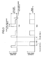
- the waveform is plotted above the y-axis when the polarities of the electrode and the work are assumed to be negative and positive respectively.
- the thickness of the coat formed on the work varies with the weight percentage of Co contained in the electrode. As shown in Fig. 2, the coat thickness, which is about 10 ⁇ m when the Co content is low, starts becoming gradually thicker at a point at which the Co content is about 30 volume %, and becomes up to nearly 10000 ⁇ m at a point at which the Co content exceeds 50 volume %.
- the thickness of the coat that can be formed is limited to about 10 ⁇ m and the coat cannot be made thicker.
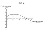
- a relation between the thickness of the coat and the processing time when the electrode does not contain the material that is hard to form a carbide is illustrated in Fig. 4. As shown in Fig. 4, in an early stage of the processing, the coat grows thicker as the processing time increases; however, the thickness of the coat does not increase after a certain point (approximately 5 min/cm 2 ).
- the coat thickness does not grow for a while, but if the processing is continued until a certain time (about 20 min/cm 2 ), the coat thickness starts decreasing this time, and finally the height of the coat becomes minus, or hollow.
- a certain time about 20 min/cm 2
- the coat thickness starts decreasing this time, and finally the height of the coat becomes minus, or hollow.
- the coat exists even though the coat looks hollow and the thickness itself is about 10 ⁇ m, which is almost the same as when the coat is processed in an appropriate time. Consequently, the processing time between 5 minutes to 20 minutes is considered to be the appropriate time.
- the plotted values are mean values of several experimental results, and actually, when the Co content is of the order of 30 volume %, the formation of the coat is unstable, sometimes causing cases that the coat does not grow high and thick, or even if the coat grows high and thick, the strength of the coat is low, in other words, the coat can be removed if it is scraped with a piece of metal and the like. Therefore, it is preferable that the Co content is higher than 50 volume %.
- the Co content is higher than 50 volume %.
- Volume percentage here signifies a proportion that is the value of a weight of the powder divided by a density of each material, and is the ratio of the volume of the material to the volume of the whole material of the powder.
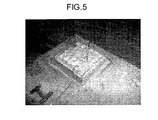
- a photograph of the coat that was formed when the Co content in the electrode was 70 volume % is shown in Fig. 5.
- the photograph exemplifies the formation of the thick coat.
- the coat that was formed had a thickness of the order of 2 mm.
- the coat was formed in 15 minutes of a processing time, and it is possible to make the coat thicker if the processing time is extended.
- a coat can be stably formed on a surface of a work with electric discharge surface treatment, provided that an electrode is used that contains more than 40 volume % of materials such as Co that are not carbonized or are hard to be carbonized.
- Co cobalt
- Ni nickel
- Fe iron
- a thick coat here signifies a closely packed coat that has a metallic luster in an internal structure (generally an outermost surface has surface roughness and seems rough having no luster since the coat is formed by means of the pulsed electric discharge).
- a deposition accumulates high if the electrode is made low in strength.
- such a deposition is not a closely packed coat but a coat that can easily be removed if it is scraped with a piece of metal and the like.
- the deposition that is described in the patent literature 1 mentioned previously and the like is not a closely packed coat but is a coat that can easily be removed if the coat is scraped with a piece of metal and the like.
- the electrode has been explained above that is manufactured by compression molding and heating the powder of Cr 3 C 2 (chromium carbide) and Co
- the green compact obtained by merely compression molding can be used as the electrode.
- the electrode must be neither too hard nor too soft but should have a proper hardness.
- a heating treatment is required. Heating the green compact enables to maintain the form and leads to solidification.
- the hardness of the electrode has a correlation with the bond strength of the powder of the electrode materials, and relates to the amount of the electrode materials to be provided to the work during the electric discharge.
- the bond strength of the electrode materials is high when the hardness of the electrode is high, only a small amount of the electrode materials is released even if the electric discharge is generated, and it is impossible to form a coat satisfactorily. Conversely, because the bond strength of the electrode materials is low when the hardness of the electrode is low, a large amount of the materials is released when the electric discharge is generated. And if the amount released is too much, it is impossible to form a closely packed coat since the energy of the pulsed electric discharge is insufficient to melt the materials.
- ingredients of a powder are the same, parameters that affect the hardness of the electrode, or the bond condition of the electrode materials, are the pressure of a press and the heating temperature.
- Fig. 6 is a schematic of a configuration of an apparatus for electric discharge surface treatment according to the first embodiment of the present invention.
- the apparatus for electric discharge surface treatment according to the embodiment includes an electrode 203, which is the electrode for electric discharge surface treatment described previously, that is formed with a green compact made by compression molding a powder that contains more than 40 volume % of metal that do not form a carbide or is hard to form a carbide, or with a green compact obtained by heat-treating the green compact; a dielectric fluid 205 that is an oil; a dielectric fluid supply unit 208 to immerse the electrode 203 and a work 204 in the dielectric fluid, or to supply the dielectric fluid 205 between the electrode 203 and the work 204; and a power source for electric discharge surface treatment 206 that generates a pulsed electric discharge by applying a voltage between the electrode 203 and the work 204.
- the electrode consists of, for example, a Cr 3 C 2 (chromium carbide) powder 201 and a Co (cobalt) powder 202, and contains, for example, more than 70 volume % Co that is a material hard to form a carbide.
- the electrode 203 and the work 204 are placed oppositely in the dielectric fluid 205, and a pulsed electric discharge is generated between the electrode 203 and the work 204 by the power source for electric discharge surface treatment 206, and with an energy of the electric discharge, a coat of the electrode material, or a coat of a substance that is generated by a reaction of the electrode materials is formed on the surface of the work.
- the electrode is given negative polarity and the work is given positive polarity.
- An arc column of the electric discharge 207 occurs between the electrode 203 and the work 204 as shown in Fig. 6.
- Forming a coat on the work 204 with the apparatus for electric discharge surface treatment described previously enables a stable formation of a thick coat on the work by means of an in-liquid pulsed electric discharge surface treatment.
- Fig. 7 illustrates a cross-section of an electrode for electric discharge surface treatment and a concept of a manufacturing method of the electrode according to a second embodiment of the present invention.
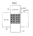
- a mixture of a Ti (titanium) powder 701 and a Co (cobalt) powder 702 is filled in a space between an upper punch 703 of a mold, a lower punch 704 of the mold, and a die 705 of the mold.
- a green compact is formed by compression molding the mixture.
- the green compact thus obtained is used as an electrode for electric discharge in the electric discharge surface machining.
- the pressure to compression mold the powder was set to about 100 MPa and the heating temperature was changed in a range of 400°C to 800°C during manufacturing the electrode.
- Ti (titanium) and Co (cobalt) are metals but there is a difference that Ti (titanium) is an active material and is extremely likely to form TiC (titanium carbide), which is a carbide, in the electric discharge atmosphere in the dielectric fluid that is the oil, while Co (cobalt) is a material that is unlikely to form a carbide.
- the powder of Ti (titanium) having a grain diameter of the order of 3 ⁇ m to 4 ⁇ m, and a powder of Co (cobalt) having a grain diameter grain diameter of the order of 4 ⁇ m to 6 ⁇ m were used.
- Ti titanium
- TiH 2 titanium hydride
- Ti (titanium) in the electrode becomes TiC (titanium carbide), a carbide, in the electric discharge atmosphere in the dielectric fluid that is the oil, and the results come out almost the same as when a carbide is initially mixed.
- TiC titanium carbide
- a peak that indicates Ti (titanium) existence was observed but a peak that indicates Ti (titanium) existence was not, observed.
- an electrode is made of a mixture of a Ti (titanium) powder and a Co (cobalt) powder, it is possible to form a thick coat stably on the surface of a work if an electrode that contains more than 40 volume % of Co (cobalt) powder as a material that is hard to be carbonized or not carbonized, is used.
- the thickness of the coat was of the order of 10 ⁇ m.
- Cr chromium carbide
- Cr chromium carbide
- a change in the thickness of the coat with a change in the amount of Co content is shown in Fig. 9.
- the conditions of the pulse of the electric discharge applied were the same as those in the first embodiment and the second embodiment.
- the electrode was given negative polarity and a work was given positive polarity.
- a processing time was 15 minutes.
- an aptness to be carbonized varies even among materials that are likely to form carbides, and materials that are less likely to be carbonized tend to form a thicker coat. It is inferred that this is because the requirement to form the thick coat is to retain a certain proportion for materials that stay behind as metal, i.e., does not become carbide, in materials that form the coat. From the results obtained in the first embodiment to the third embodiment, it can be concluded that the necessary condition to form a thick closely-packed coat is that the proportion of the materials that stay behind as metal in the coat is higher than about 30% in volume.
- an electrode is made of a mixture of a Cr (chromium) powder and a Co (cobalt) powder, it is possible to form a thick coat stably on the surface of a work if an electrode that contains more than 40 volume % of Co (cobalt) powder as a material that is hard to be carbonized or not carbonized, is used. Furthermore, in this case, it is possible to particularly form a thick coat stably on the surface of the work if an electrode that contains more than 20 volume % of Co is used.
- Co cobalt
- Cr chromium
- Fig. 10 illustrates a cross-section of an electrode for electric discharge surface treatment and a concept of manufacturing method of the electrode according to a fourth embodiment of the present invention.
- a mixture of a Mo (molybdenum) powder 1001, a Cr (chromium) powder 1002, a Si (silicon) 1003 powder, and a Co (cobalt) powder 1004 is filled in a space between an upper punch 1005 of a mold, a lower punch 1006 of the mold, and a die 1007 of the mold.
- a compound ratio of the mixture is Mo (molybdenum) 28 weight %, Cr (chromium) 17 weight %, Si (silicon) 3 weight %, Co (cobalt) 52 weight %.
- a volume percentage of Co (cobalt) in this case is about 50%.
- a green compact is formed by compression molding the mixture. The green compact thus obtained is used as an electrode for the electric discharge in electric discharge surface machining.
- the combination and the proportion of Mo (molybdenum) 28 weight %, Cr (chromium) 17 weight %, Si (silicon) 3 weight %, and Co (cobalt) 52 weight % are used to obtain a material that has abrasion resistance in high-temperature environment.
- the electrode that is composed in such proportion has abrasion resistance because of a hardness of the materials and a lubrication exhibited by Cr 3 C 2 (chromium carbide) that is formed by oxidation of Cr (chromium) in high-temperature environment.
- the pressure of the compression mold was set to about 100 MPa and the heating temperature was set in a range of 400°C to 800°C during manufacturing the electrode.
- a small amount (2% to 3% by weight) of a wax was mixed with the powder to be pressed to obtain better formability.
- the wax gets removed during the heating.
- a powder of each material having a grain diameter of the order of 2 ⁇ m to 6 ⁇ m was used.
- the electrode was given negative polarity and a work was given positive polarity.
- an apparatus for electric discharge surface treatment similar to the apparatus in Fig. 6 can be composed. And when the coat is formed on the surface of the work by means of a pulsed electric discharge generated by the apparatus for electric discharge surface treatment, it is possible to form a thick coat on a work material without causing a strain due to the pulsed electric discharge in a dielectric fluid that is an oil. Furthermore, it was confirmed that the coat formed had abrasion resistance even in high-temperature environment, which means that a thick coat with good quality was formed.
- the coat that has various functions such as abrasion resistance and the like by forming the coat on the surface of the work by means of in-liquid pulsed electric discharge machining with the electrode that is made with the materials compounded in the proportion described previously.
- Other such materials include a Stellite that consists of "Cr (chromium) 25 weight %, Ni (nickel) 10 weight %, W (tungsten) 7 weight %, and Co (cobalt) for the rest", or "Cr (chromium) 20 weight %, Ni (nickel) 10 weight %, W (tungsten) 15 weight %, and Co (cobalt) for the rest". Since Stellite has excellent corrosion resistance and high-temperature hardness, it is a material that is usually applied for coating by welding and the like to a part that requires such properties, and is suitable for coating when corrosion resistance and high-temperature hardness are required.
- nickel based materials compounded in such a proportion of "Cr (chromium) 15 weight %, Fe (iron) 8 weight %, Ni (nickel) for the rest” and “Cr (chromium) 21 weight %, Mo (molybdenum) 9 weight %, Ta (tantalum) 4 weight %, and Ni (nickel) for the rest", and "Cr (chromium) 19 weight %, Ni (nickel) 53 weight %, Mo (molybdenum) 3 weight %, (Cb + Ta) 5 weight %, Ti (titanium) 0.8 weight %, Al (aluminum) 0.6 weight %, Fe (iron) for the rest” and the like are materials that have heat resistance, and are suitable for coating when heat resistance is required.
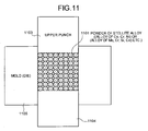
- Fig. 11 illustrates a cross-section of an electrode for electric discharge surface treatment and a concept of manufacturing method of the electrode according to a fifth embodiment of the present invention.
- a powder of Stellite alloy (alloy of Co, Cr, Ni) 1101 is filled in a space between an upper punch 1103 of a mold, a lower punch 1104 of the mold, and a die 1105 of the mold.
- a green compact is formed by compression molding the mixture. The green compact thus obtained is used as an electrode for electric discharge in electric discharge surface machining.
- the pressure of the compression mold was set to about 100 MPa and the heating temperature was changed in a range of 600°C to 800°C.
- a small amount (2% to 3% by weight) of a wax was mixed with the powder to be pressed to obtain better formability.
- the wax gets removed during the heating.
- the powder of each material having a grain diameter of the order of 2 ⁇ m to 6 ⁇ m was used.
- the electrode was given negative polarity and a work was given positive polarity.
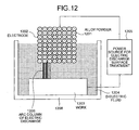
- the apparatus for electric discharge surface treatment includes an electrode 1202 that is made of the powder of the alloy compounded in the proportion described previously; a dielectric fluid 1204 that is an oil; a dielectric fluid supply unit 1208 to immerse the electrode 1202 and a work 1203 in the dielectric fluid, or to supply the dielectric fluid 1204 between the electrode 1202 and the work 1203; and a power source for electric discharge surface treatment 1205 that generates a pulsed electric discharge by applying a voltage between the electrode 1202 and the work 1203.
- the electrode is composed of an alloy powder 1201. Components that do not relate directly to the present invention, such as a driving unit that controls a relative position of the power source for electric discharge surface treatment 1205 and the work 1203, are omitted.
- the electrode material is transferred onto the work each time the electric discharge is generated.
- the electrode material is made of a powder
- the powder is the alloy made into powder, therefore, the material is homogeneous, and there is no variation in the material when it is transferred onto the electrode 1202. Consequently, it is possible to form a coat with good quality without a compositional variation caused by the nouniformity in the electrode material.
- the electrode by making the electrode with the powder that is obtained by powdering an alloy material composed of several elements in a specified proportion, it becomes possible to eliminate the compositional variation in the electrode. And by electric discharge surface machining with the electrode, it becomes possible to form a thick coat stably on a surface of a work, and to make the composition of the coat uniform.
- the alloy to be powdered certainly may be other combinations, and for example, an alloy that is made in such a mixing ratio as "Cr (chromium) 25 weight %, Ni (nickel) 10 weight %, W (tungsten) 7 weight %, and Co (cobalt) for the rest" can be used.
- alloys that are made in mixing ratios such as "Mo (molybdenum) 28 weight %, Cr (chromium) 17 weight %, Si (silicon) 3 weight %, and Co (cobalt) for the rest", “Cr (chromium) 15 weight %, Fe (iron) 8 weight %, and Ni (nickel) for the rest", “Cr (chromium) 21 weight %, Mo (molybdenum) 9 weight %, Ta (tantalum) 4 weight %, and Ni (nickel) for the rest”, and “Cr (chromium) 19 weight %, Ni (nickel) 53 weight %, Mo (molybdenum) 3 weight %, (Cb + Ta) 5 weight %, Ti (titanium) 0.8 weight %, Al (aluminum) 0.6 weight %, and Fe (iron) for the rest” can also be used.
- a property of the material such as the hardness, may be different if the mixing ratio of the alloy
- an alloy that is compounded in an alloy mixing ratio of "Cr (chromium) 25 weight %, Ni (nickel) 10 weight %, W (tungsten) 7 weight %, and Co (cobalt) for the rest” is relatively soft, and an alloy that is compounded in a mixing ratio of "Mo (molybdenum) 28 weight %, Cr (chromium) 17 weight %, Si (silicon) 3 weight %, and Co (cobalt) for the rest" is relatively hard material.
- a volume percentage of Co is ((weight % of Co)/(specific gravity of Co) ⁇ (((weight % of Cr)/(specific gravity of Cr))+((weight % of Co)/(specific gravity of Co))) as described previously.
- Cr (chromium) is a material that forms a carbide, it is less likely to form a carbide compared to an active material such as Ti.
- Fig. 13 illustrates a cross-section of an electrode for electric discharge surface treatment and a concept of manufacturing method of the electrode according to a sixth embodiment of the present invention.
- a mixture of a Co alloy powder 1301 and a Co (cobalt) powder 1302 is filled in a space between an upper punch 1303 of a mold, a lower punch 1304 of the mold, and a die 1305 of the mold.
- a green compact is formed by compression molding the mixture.
- the green compact thus obtained is used as an electrode for electric discharge in electric discharge surface machining.
- the pressure of the compression mold is set to about 100 MPa and the heating temperature is set in a range of 600°C to 800°C during manufacturing the electrode.
- the mixing ratio of the Co alloy powder 1301 is "Mo (molybdenum) 28 weight %, Cr (chromium) 17 weight %, Si (silicon) 3 weight %, Co (cobalt) for the rest".
- the Co alloy powder 1301 is obtained by powdering an alloy material compounded with such a mixing ratio.
- the Co alloy powder and the Co powder 1302 both having a grain diameter of the order of 2 ⁇ m to 6 ⁇ m are used.
- the alloy having such a mixing ratio as "Mo (molybdenum) 28 weight %, Cr (chromium) 17 weight %, Si (silicon) 3 weight %, Co (cobalt) for the rest” is the alloy that is used as a material that requires abrasion resistance in high-temperature environment.
- the alloy has abrasion resistance because of a hardness of the materials and a lubrication exhibited by Cr 3 C 2 (chromium carbide) that is formed by oxidation of Cr (chromium) in high-temperature environment. Therefore, with an electrode that contains this alloy powder, it is possible to form a coat that has an excellent abrasion resistance.
- a void ratio in the coat can be reduced to about 3% to 4%.
- Ni or Fe, other than Co, can be used as a material that brings about such effectiveness, and more than one material can be mixed among such materials.
- Fig. 14 is an explanatory diagram that indicates a transition of materials applied to aircraft engines.
- the aircraft engines for example the engine blades
- heat-resistant alloys are used as the material applied.
- An ordinary casting was used before; however, special castings such as a single crystal alloy, a unidirectionally solidified alloy and the like are used now-a-days.
- these materials are heat-resistant materials in high-temperature environment, there is a drawback that it gets easily damaged if a major unevenness in temperature occurs due to entering of heat locally as in the case of the welding.
- the aircraft engines are considered as a whole, because in most cases, other materials are attached by welding and thermal spray coating there are problems that it gets easily damaged due to concentration of the heat locally, and the yield is low.
- a period of the pulse width te shown in Fig. 3 is the period that the electric discharge is generated and the electric discharge delay time td and the pause time to are the period that the electric discharge is not generated, in other words, the period that the heat is not applied to the work.
- the following electric discharge to be generated is applied on another part; therefore, it can be understood that there is less concentration of the heat compared to welding.
- the electrode for electric discharge surface treatment according to the present invention is suitable for application in a surface treatment related industry that forms a coat on a surface of a workpiece, and is especially suitable for application in the surface treatment related industry that forms a thick coat on a surface of a workpiece.
Landscapes
- Chemical & Material Sciences (AREA)
- Mechanical Engineering (AREA)
- Engineering & Computer Science (AREA)
- Materials Engineering (AREA)
- Organic Chemistry (AREA)
- Metallurgy (AREA)
- Chemical Kinetics & Catalysis (AREA)
- Manufacturing & Machinery (AREA)
- Composite Materials (AREA)
- Other Surface Treatments For Metallic Materials (AREA)
- Electrical Discharge Machining, Electrochemical Machining, And Combined Machining (AREA)
- Powder Metallurgy (AREA)
- Application Of Or Painting With Fluid Materials (AREA)
- Treatments Of Macromolecular Shaped Articles (AREA)
Abstract
Description
These facts well conform to the actual experimental results.
Claims (31)
- An electrode for electric discharge surface treatment, the electrode is a green compact made by compression molding metallic powders or metallic compound powders and used for electric discharge surface treatment in which a pulsed electric discharge is generated between the electrode and a work in a dielectric fluid to form by the electric discharge energy on the surface of the work a coat of a material of the electrode or of a substance that is generated by a reaction of the electrode due to the electric discharge energy, wherein the electrode contains 40 volume % or more metallic material that is not carbonized or is hard to be carbonized.
- The electrode for electric discharge surface treatment according to claim 1, wherein the metallic material that is not carbonized or is hard to be carbonized is Co, Ni, or Fe.
- An electrode for electric discharge surface treatment, the electrode is a green compact made by compression molding metallic powders or metallic compound powders and used for electric discharge surface treatment in which a pulsed electric discharge is generated between the electrode and a work in a dielectric fluid to form by the electric discharge energy on the surface of the work a coat of a material of the electrode or of a substance that is generated by a reaction of the electrode due to the electric discharge energy, wherein the electrode is made from a powder of an alloy material that is alloyed by mixing a plurality of elements in a predetermined ratio.
- The electrode for electric discharge surface treatment according to claim 3, made by mixing a powder of at least one of Co, Ni, and Fe to the powder of the alloy material.
- The electrode for electric discharge surface treatment according to claim 3, wherein the alloy material contains 40 volume % or more metallic material that is not carbonized or is hard to be carbonized.
- The electrode for electric discharge surface treatment according to claim 5, made by mixing a powder of at least one of Co, Ni, and Fe to the powder of the alloy material.
- The electrode for electric discharge surface treatment according to claim 5, wherein the metallic material that is not carbonized or is hard to be carbonized is Co, Ni, or Fe.
- The electrode for electric discharge surface treatment according to claim 3, wherein the alloy material is a Co alloy containing Cr, Ni, and W with Co as a main component; a Co alloy containing Mo, Cr, and Si with Co as a main component; an Ni alloy containing Cr, and Fe with Ni as a main component; an Ni alloy containing Cr, Mo and Ta with Ni as a main component; and an Fe alloy containing Cr, Ni, Mo, (Cb + Ta), Ti, and AI with Fe as a main component.
- The electrode for electric discharge surface treatment according to claim 8, made by mixing a powder of at least one of Co, Ni, and Fe to the powder of the alloy material.
- A method of electric discharge surface treatment, comprising:generating pulsed electric discharge in a dielectric fluid between a green compact electrode and a work, the electrode being made by compression molding a metallic powder or metallic compound powders; andforming a coat that contains a carbide and a non-carbonized metallic component in a predetermined ratio based on materials supplied from the green compact electrode on a surface of the work using an energy of the electric discharge.
- The method of electric discharge surface treatment according to claim 10, wherein the ratio of the non-carbonized metallic component is 30 volume % or more.
- The method of electric discharge surface treatment according to claim 11, wherein the coat is formed on the surface of the work by letting discharge the electrode that contains 40 volume % or more metallic material that is not carbonized or is hard to be carbonized.
- The method of electric discharge surface treatment according to claim 10, wherein the metallic material that is not carbonized or is hard to be carbonized is Co, Ni, or Fe.
- The method of electric discharge surface treatment according to claim 10, wherein the material of the work is a directional control alloy such as single crystal alloy or unidirectionally solidified alloy.
- A method of electric discharge surface treatment of using an electrode that is a green compact made by compression molding metallic powders or metallic compound powders for electric discharge surface treatment in which a pulsed electric discharge is generated between the electrode and a work in a dielectric fluid to form by the electric discharge energy on the surface of the work a coat of a material of the electrode or of a substance that is generated by a reaction of the electrode due to the electric discharge energy, wherein the coat is formed by using an electrode made from a powder of an alloy material that is alloyed by mixing a plurality of elements in a predetermined ratio.
- The method of electric discharge surface treatment according to claim 15, wherein the electrode is made by mixing a powder of at least one of Co, Ni, and Fe to the powder of the alloy material.
- The method of electric discharge surface treatment according to claim 15, wherein the material of the work is a directional control alloy such as single crystal alloy or unidirectionally solidified alloy.
- The method of electric discharge surface treatment according to claim 15, wherein the alloy material contains 40 volume % or more metallic material that is not carbonized or is hard to be carbonized.
- The method of electric discharge surface treatment according to claim 18, wherein the electrode is made by mixing a powder of the alloy material with a powder of at least one of Co, Ni, and Fe.
- The method of electric discharge surface treatment according to claim 18, wherein the metallic material that is not carbonized or is hard to be carbonized is Co, Ni, or Fe.
- The method of electric discharge surface treatment according to claim 15, wherein the alloy material is a Co alloy containing Cr, Ni, and W with Co as a main component; a Co alloy containing Mo, Cr, and Si with Co as a main component; an Ni alloy containing Cr, and Fe with Ni as a main component; an Ni alloy containing Cr, Mo and Ta with Ni as a main component; and an Fe alloy containing Cr, Ni, Mo, (Cb + Ta), Ti, and Al with Fe as a main component.
- The method of electric discharge surface treatment according to claim 21, wherein the electrode is made by mixing a powder of at least one of Co, Ni, and Fe to the powder of the alloy material.
- An apparatus for electric discharge surface treatment, comprising:an electrode of a green compact made by compression molding powders containing 40 volume % or more metallic material that is not carbonized or is hard to be carbonized;a dielectric fluid supply unit to immerse the electrode and a work in the dielectric fluid or that supplies the dielectric fluid between the electrode and the work; anda power source unit that generates pulsed electric discharge by applying voltage between the electrode and the work.
- The apparatus for electric discharge surface treatment according to claim 23, wherein the metallic material that is not carbonized or is hard to be carbonized is Co, Ni, or Fe.
- An apparatus for electric discharge surface treatment, comprising:an electrode of green compact made from a powder of an alloy material that is alloyed by mixing a plurality of elements in a predetermined ratio;a dielectric fluid supply unit to immerse the electrode and a work in the dielectric fluid or that supplies the dielectric fluid between the electrode and the work; anda power source unit that generates pulsed electric discharge by applying voltage between the electrode and the work.
- The apparatus for electric discharge surface treatment according to claim 25, wherein the electrode is made by mixing a powder of at least one of Co, Ni, and Fe to the powder of the alloy material.
- The apparatus for electric discharge surface treatment according to claim 25, wherein the alloy material contains 40 volume % or more metallic material that is not carbonized or is hard to be carbonized.
- The apparatus for electric discharge surface treatment according to claim 27, wherein the electrode is made by mixing a powder of at least one of Co, Ni, and Fe to the powder of the alloy material.
- The apparatus for electric discharge surface treatment according to claim 27, wherein the metallic material that is not carbonized or is hard to be carbonized is Co, Ni, or Fe.
- The apparatus for electric discharge surface treatment according to claim 25, wherein the alloy material is a Co alloy containing Cr, Ni, and W with Co as a main component; a Co alloy containing Mo, Cr, and Si with Co as a main component; an Ni alloy containing Cr, and Fe with Ni as a main component; an Ni alloy containing Cr, Mo and Ta with Ni as a main component; and an Fe alloy containing Cr, Ni, Mo, (Cb + Ta), Ti, and Al with Fe as a main component.
- The apparatus for electric discharge surface treatment according to claim 30, wherein the electrode is made by mixing a powder of at least one of Co, Ni, and Fe to the powder of the alloy material.
Applications Claiming Priority (3)
| Application Number | Priority Date | Filing Date | Title |
|---|---|---|---|
| JP2002220971 | 2002-07-30 | ||
| JP2002220971 | 2002-07-30 | ||
| PCT/JP2003/009687 WO2004011696A1 (en) | 2002-07-30 | 2003-07-30 | Electrode for electric discharge surface treatment, electric discharge surface treatment method and electric discharge surface treatment apparatus |
Publications (3)
| Publication Number | Publication Date |
|---|---|
| EP1526191A1 true EP1526191A1 (en) | 2005-04-27 |
| EP1526191A4 EP1526191A4 (en) | 2008-11-05 |
| EP1526191B1 EP1526191B1 (en) | 2010-07-21 |
Family
ID=31184828
Family Applications (1)
| Application Number | Title | Priority Date | Filing Date |
|---|---|---|---|
| EP03771434A Expired - Lifetime EP1526191B1 (en) | 2002-07-30 | 2003-07-30 | Electrode for electric discharge surface treatment, electric discharge surface treatment method and electric discharge surface treatment apparatus |
Country Status (13)
| Country | Link |
|---|---|
| US (2) | US7537808B2 (en) |
| EP (1) | EP1526191B1 (en) |
| JP (1) | JP4137886B2 (en) |
| KR (1) | KR20050026525A (en) |
| CN (1) | CN100529182C (en) |
| AT (1) | ATE474946T1 (en) |
| CA (1) | CA2494366C (en) |
| DE (1) | DE60333457D1 (en) |
| ES (1) | ES2347551T3 (en) |
| IL (2) | IL165179A0 (en) |
| RU (1) | RU2294397C2 (en) |
| TW (1) | TWI250908B (en) |
| WO (1) | WO2004011696A1 (en) |
Cited By (5)
| Publication number | Priority date | Publication date | Assignee | Title |
|---|---|---|---|---|
| WO2004106587A1 (en) | 2003-05-29 | 2004-12-09 | Mitsubishi Denki Kabushiki Kaisha | Discharge surface treatment electrode, process for producing discharge surface treatment electrode, discharge surface treatment apparatus and discharge surface treatment method |
| EP1630254A4 (en) * | 2003-05-29 | 2009-07-22 | Mitsubishi Electric Corp | ELECTRODE FOR DISCHARGE SURFACE TREATMENT, DISCHARGE SURFACE TREATMENT METHOD, AND DISCHARGE SURFACE TREATMENT APPARATUS |
| US7910176B2 (en) | 2003-06-05 | 2011-03-22 | Mitsubishi Denki Kabushiki Kaisha | Electrode for discharge surface treatment, manufacturing method and evaluation method for electrode for discharge surface treatment, discharge surface treatment apparatus, and discharge surface treatment method |
| EP2500606A4 (en) * | 2009-11-13 | 2013-05-22 | Ihi Corp | Seal structure of fluid device |
| EP3540095A4 (en) * | 2016-11-09 | 2020-03-25 | IHI Corporation | SLIDING ELEMENT WITH ABRASION-RESISTANT COATING FILM AND METHOD FOR FORMING ABRASION-RESISTANT COATING FILM |
Families Citing this family (21)
| Publication number | Priority date | Publication date | Assignee | Title |
|---|---|---|---|---|
| JPH0535378U (en) * | 1991-10-23 | 1993-05-14 | リ−ド産業株式会社 | Writing instrument having a solid core such as a modified core |
| CN100529182C (en) | 2002-07-30 | 2009-08-19 | 三菱电机株式会社 | Electrode for electric discharge surface treatment, electric discharge surface treatment method and electric discharge surface treatment apparatus |
| US9284647B2 (en) * | 2002-09-24 | 2016-03-15 | Mitsubishi Denki Kabushiki Kaisha | Method for coating sliding surface of high-temperature member, high-temperature member and electrode for electro-discharge surface treatment |
| WO2004029329A1 (en) * | 2002-09-24 | 2004-04-08 | Ishikawajima-Harima Heavy Industries Co., Ltd. | Method for coating sliding surface of high temperature member, and high temperature member and electrode for electric discharge surface treatment |
| CA2483528C (en) * | 2002-10-09 | 2015-07-21 | Ishikawajima-Harima Heavy Industries Co., Ltd. | Rotating member and method for coating the same |
| EP1643008B1 (en) * | 2003-06-11 | 2017-11-15 | Mitsubishi Denki Kabushiki Kaisha | Electrical- discharge surface-treatment method |
| JPWO2006057053A1 (en) * | 2004-11-29 | 2008-06-05 | 三菱電機株式会社 | Discharge surface treatment electrode, discharge surface treatment method, and discharge surface treatment apparatus |
| JP4692541B2 (en) * | 2005-03-09 | 2011-06-01 | 株式会社Ihi | Surface treatment method and repair method |
| WO2007043102A1 (en) * | 2005-09-30 | 2007-04-19 | Mitsubishi Denki Kabushiki Kaisha | Electrode for discharge surface treatment, discharge surface treatment method, and film |
| WO2007113914A1 (en) | 2006-04-05 | 2007-10-11 | Mitsubishi Electric Corporation | Coating and method of forming coating |
| WO2007148716A1 (en) * | 2006-06-21 | 2007-12-27 | Bosch Corporation | Surface treating method by electric discharge, and dressing method |
| WO2008032359A1 (en) * | 2006-09-11 | 2008-03-20 | Mitsubishi Electric Corporation | Process for producing electrode for electric discharge surface treatment and electrode for electric discharge surface treatment |
| US20110036721A1 (en) * | 2008-02-05 | 2011-02-17 | Masahiko Kobayashi | Electrical Discharge Coating Method and Green Compact Electrode Used Therein |
| RU2371520C1 (en) * | 2008-07-25 | 2009-10-27 | Федеральное государственное образовательное учреждение высшего профессионального образования "Государственный технологический университет "Московский институт стали и сплавов" | Composition electrode material for receiving of dispersion-reinforced by nanoparticles coatings |
| WO2010016121A1 (en) | 2008-08-06 | 2010-02-11 | 三菱電機株式会社 | Electric discharge surface treatment method |
| WO2010095590A1 (en) * | 2009-02-18 | 2010-08-26 | 株式会社Ihi | Electrode manufacturing method and electric discharge surface treatment used therein |
| WO2010119865A1 (en) * | 2009-04-14 | 2010-10-21 | 株式会社Ihi | Discharge surface treatment electrode and method for manufacturing same |
| EP2474646B1 (en) * | 2009-09-03 | 2015-03-04 | IHI Corporation | Electric discharge surface treatment |
| US20130069015A1 (en) * | 2010-05-26 | 2013-03-21 | Mitsubishi Electric Corporation | Electrode for electric-discharge surface treatment and electric-discharge surface treatment coating |
| US20130164496A1 (en) * | 2010-09-16 | 2013-06-27 | Mitsubishi Electric Corporation | Surface layer forming method using electrical discharge machining and surface layer |
| WO2012035580A1 (en) * | 2010-09-16 | 2012-03-22 | 三菱電機株式会社 | Discharge surface treatment method |
Family Cites Families (34)
| Publication number | Priority date | Publication date | Assignee | Title |
|---|---|---|---|---|
| US3585342A (en) * | 1970-06-03 | 1971-06-15 | Stackpole Carbon Co | Edm electrode |
| SU1521542A1 (en) * | 1987-06-18 | 1989-11-15 | Всесоюзное Научно-Производственное Объединение Восстановления Деталей "Ремдеталь" | Method of spark-erosion alloying |
| SU1463410A1 (en) * | 1987-08-05 | 1989-03-07 | Институт горного дела Дальневосточного отделения АН СССР | Material for electric discharge application of a coating |
| US4882125A (en) | 1988-04-22 | 1989-11-21 | Inco Alloys International, Inc. | Sulfidation/oxidation resistant alloys |
| JP3001314B2 (en) | 1991-12-25 | 2000-01-24 | 三菱電機株式会社 | Electric discharge machine |
| RU2007274C1 (en) * | 1991-06-24 | 1994-02-15 | Институт материаловедения Дальневосточного отделения РАН | Electrode material for electric-spark alloying, and a method of its making |
| JP3093846B2 (en) | 1991-11-18 | 2000-10-03 | 科学技術振興事業団 | Surface treatment method for metal materials |
| US5312580A (en) * | 1992-05-12 | 1994-05-17 | Erickson Diane S | Methods of manufacturing porous metal alloy fuel cell components |
| JPH06182626A (en) * | 1992-12-17 | 1994-07-05 | Hitachi Ltd | High corrosion resistance surface treatment method |
| JP3098654B2 (en) | 1993-03-24 | 2000-10-16 | 科学技術振興事業団 | Surface treatment method and apparatus by electric discharge machining |
| JP3271836B2 (en) | 1993-08-31 | 2002-04-08 | 科学技術振興事業団 | Surface treatment method for aluminum and its alloys by submerged discharge |
| JP3271844B2 (en) | 1993-12-31 | 2002-04-08 | 科学技術振興事業団 | Surface treatment method for metallic materials by submerged discharge |
| JP3363284B2 (en) | 1995-04-14 | 2003-01-08 | 科学技術振興事業団 | Electrode for electric discharge machining and metal surface treatment method by electric discharge |
| US5558479A (en) * | 1995-05-19 | 1996-09-24 | Illinois Tool Works Inc. | Wall anchor accommodating fasteners of varying thread diameters |
| US5858479A (en) | 1996-01-17 | 1999-01-12 | Japan Science And Technology Corporation | Surface treating method by electric discharge |
| JP3537939B2 (en) | 1996-01-17 | 2004-06-14 | 独立行政法人 科学技術振興機構 | Surface treatment by submerged discharge |
| JP3627784B2 (en) | 1997-06-10 | 2005-03-09 | 独立行政法人科学技術振興機構 | Discharge surface treatment method |
| JPH1122915A (en) | 1997-06-27 | 1999-01-26 | Babcock Hitachi Kk | Method and device therefor for burning sulfur-containing fuel |
| JP4020169B2 (en) * | 1997-10-03 | 2007-12-12 | 株式会社石塚研究所 | Electrode rod for spark welding using combustion synthesis reaction, its production method, and spark-welded metal coating method using this electrode |
| JP3596272B2 (en) | 1998-02-16 | 2004-12-02 | 三菱電機株式会社 | Discharge surface treatment apparatus and discharge surface treatment method using the same |
| JPH11260480A (en) | 1998-03-13 | 1999-09-24 | Mitsubishi Electric Corp | Micro component connection device |
| JP3562298B2 (en) | 1998-03-16 | 2004-09-08 | 三菱電機株式会社 | Discharge surface treatment equipment |
| DE19964388B3 (en) * | 1998-05-13 | 2014-03-20 | Mitsubishi Denki K.K. | Process for forming a hard coating and apparatus for carrying it out |
| JP5547864B2 (en) | 1999-02-24 | 2014-07-16 | 三菱電機株式会社 | Discharge surface treatment method and apparatus |
| JP2000345367A (en) | 1999-05-31 | 2000-12-12 | Nissan Motor Co Ltd | Gear surface treatment method |
| DE19983550B4 (en) | 1999-07-16 | 2009-07-09 | Mitsubishi Denki K.K. | Electrode for a spark discharge coating and manufacturing method therefor |
| WO2001023641A1 (en) | 1999-09-30 | 2001-04-05 | Mitsubishi Denki Kabushiki Kaisha | Electric discharge surface treating electrode and production method thereof and electric discharge surface treating method |
| US6808604B1 (en) | 1999-09-30 | 2004-10-26 | Mitsubishi Denki Kabushiki Kaisha | Discharge surface treatment electrode, manufacturing method thereof and discharge surface treating method |
| JP2001138141A (en) * | 1999-11-19 | 2001-05-22 | Kazuo Sawaguchi | Method for surface coating treatment using submerged discharge and consumable electrode used therefor |
| DE10031102C2 (en) * | 2000-06-30 | 2003-03-06 | Forschungszentrum Juelich Gmbh | Process for producing a composite body, in particular an electrode with temperature-resistant conductivity |
| JP2002020882A (en) | 2000-07-04 | 2002-01-23 | Suzuki Motor Corp | Sliding member and manufacturing method thereof |
| JP3902421B2 (en) | 2001-06-15 | 2007-04-04 | スズキ株式会社 | Aluminum alloy surface treatment electrode and method for producing the same |
| CA2450679C (en) * | 2001-06-29 | 2010-08-31 | Nextech Materials, Ltd. | Nano-composite electrodes and method of making the same |
| CN100529182C (en) | 2002-07-30 | 2009-08-19 | 三菱电机株式会社 | Electrode for electric discharge surface treatment, electric discharge surface treatment method and electric discharge surface treatment apparatus |
-
2003
- 2003-07-30 CN CNB038183145A patent/CN100529182C/en not_active Expired - Fee Related
- 2003-07-30 DE DE60333457T patent/DE60333457D1/en not_active Expired - Lifetime
- 2003-07-30 WO PCT/JP2003/009687 patent/WO2004011696A1/en not_active Ceased
- 2003-07-30 US US10/516,506 patent/US7537808B2/en not_active Expired - Lifetime
- 2003-07-30 AT AT03771434T patent/ATE474946T1/en not_active IP Right Cessation
- 2003-07-30 TW TW092120765A patent/TWI250908B/en not_active IP Right Cessation
- 2003-07-30 RU RU2005105333/02A patent/RU2294397C2/en active
- 2003-07-30 ES ES03771434T patent/ES2347551T3/en not_active Expired - Lifetime
- 2003-07-30 CA CA2494366A patent/CA2494366C/en not_active Expired - Lifetime
- 2003-07-30 KR KR1020057001502A patent/KR20050026525A/en not_active Ceased
- 2003-07-30 JP JP2004524314A patent/JP4137886B2/en not_active Expired - Lifetime
- 2003-07-30 EP EP03771434A patent/EP1526191B1/en not_active Expired - Lifetime
-
2004
- 2004-11-11 IL IL16517904A patent/IL165179A0/en not_active IP Right Cessation
-
2006
- 2006-11-09 IL IL179152A patent/IL179152A/en not_active IP Right Cessation
-
2008
- 2008-08-20 US US12/194,970 patent/US8377339B2/en not_active Expired - Fee Related
Cited By (8)
| Publication number | Priority date | Publication date | Assignee | Title |
|---|---|---|---|---|
| WO2004106587A1 (en) | 2003-05-29 | 2004-12-09 | Mitsubishi Denki Kabushiki Kaisha | Discharge surface treatment electrode, process for producing discharge surface treatment electrode, discharge surface treatment apparatus and discharge surface treatment method |
| EP1630254A4 (en) * | 2003-05-29 | 2009-07-22 | Mitsubishi Electric Corp | ELECTRODE FOR DISCHARGE SURFACE TREATMENT, DISCHARGE SURFACE TREATMENT METHOD, AND DISCHARGE SURFACE TREATMENT APPARATUS |
| EP1643007A4 (en) * | 2003-05-29 | 2009-07-29 | Mitsubishi Electric Corp | DISCHARGE SURFACE-PROCESSING ELECTRODE, METHOD FOR PRODUCING DISCHARGE-SURFACE-PROCESSING ELECTRODE, DISCHARGE-SURFACE-PROCESSING APPARATUS, AND DISCHARGE SURFACE-TREATING METHOD |
| US7834291B2 (en) | 2003-05-29 | 2010-11-16 | Mitsubishi Denki Kabushiki Kaisha | Electrode for electric discharge surface treatment, and method and apparatus for electric discharge surface treatment |
| US7910176B2 (en) | 2003-06-05 | 2011-03-22 | Mitsubishi Denki Kabushiki Kaisha | Electrode for discharge surface treatment, manufacturing method and evaluation method for electrode for discharge surface treatment, discharge surface treatment apparatus, and discharge surface treatment method |
| EP2500606A4 (en) * | 2009-11-13 | 2013-05-22 | Ihi Corp | Seal structure of fluid device |
| EP3540095A4 (en) * | 2016-11-09 | 2020-03-25 | IHI Corporation | SLIDING ELEMENT WITH ABRASION-RESISTANT COATING FILM AND METHOD FOR FORMING ABRASION-RESISTANT COATING FILM |
| US11673194B2 (en) | 2016-11-09 | 2023-06-13 | Ihi Corporation | Slidable component including wear-resistant coating and method of forming wear-resistant coating |
Also Published As
| Publication number | Publication date |
|---|---|
| TW200408482A (en) | 2004-06-01 |
| JP4137886B2 (en) | 2008-08-20 |
| CN1671887A (en) | 2005-09-21 |
| CN100529182C (en) | 2009-08-19 |
| US20050211165A1 (en) | 2005-09-29 |
| US20090092845A1 (en) | 2009-04-09 |
| DE60333457D1 (en) | 2010-09-02 |
| RU2294397C2 (en) | 2007-02-27 |
| IL165179A0 (en) | 2005-12-18 |
| RU2005105333A (en) | 2005-07-27 |
| US7537808B2 (en) | 2009-05-26 |
| KR20050026525A (en) | 2005-03-15 |
| ATE474946T1 (en) | 2010-08-15 |
| WO2004011696A1 (en) | 2004-02-05 |
| JPWO2004011696A1 (en) | 2005-11-24 |
| CA2494366C (en) | 2012-10-09 |
| US8377339B2 (en) | 2013-02-19 |
| IL179152A (en) | 2011-02-28 |
| ES2347551T3 (en) | 2010-11-02 |
| EP1526191B1 (en) | 2010-07-21 |
| TWI250908B (en) | 2006-03-11 |
| IL179152A0 (en) | 2007-03-08 |
| EP1526191A4 (en) | 2008-11-05 |
| CA2494366A1 (en) | 2004-02-05 |
Similar Documents
| Publication | Publication Date | Title |
|---|---|---|
| US8377339B2 (en) | Electrode for electric discharge surface treatment, method of electric discharge surface treatment, and apparatus for electric discharge surface treatment | |
| JP3271844B2 (en) | Surface treatment method for metallic materials by submerged discharge | |
| US8658005B2 (en) | Electrical-discharge surface-treatment method | |
| JP4563318B2 (en) | Discharge surface treatment electrode, discharge surface treatment apparatus, and discharge surface treatment method | |
| JP5121933B2 (en) | Discharge surface treatment method | |
| CN1322165C (en) | Electric discharge surface treating electrode and production method thereof and electric discharge surface treating method | |
| US7834291B2 (en) | Electrode for electric discharge surface treatment, and method and apparatus for electric discharge surface treatment | |
| JP4608220B2 (en) | Discharge surface treatment electrode and discharge surface treatment method | |
| JP2005214054A (en) | Turbine parts and gas turbines | |
| JP2004060013A (en) | Electrode for discharge surface treatment and discharge surface treatment method |
Legal Events
| Date | Code | Title | Description |
|---|---|---|---|
| PUAI | Public reference made under article 153(3) epc to a published international application that has entered the european phase |
Free format text: ORIGINAL CODE: 0009012 |
|
| 17P | Request for examination filed |
Effective date: 20041105 |
|
| AK | Designated contracting states |
Kind code of ref document: A1 Designated state(s): AT BE BG CH CY CZ DE DK EE ES FI FR GB GR HU IE IT LI LU MC NL PT SE SI SK TR |
|
| RAP1 | Party data changed (applicant data changed or rights of an application transferred) |
Owner name: ISHIKAWAJIMA-HARIMA HEAVY INDUSTRIES CO., LTD. Owner name: MITSUBISHI DENKI KABUSHIKI KAISHA |
|
| A4 | Supplementary search report drawn up and despatched |
Effective date: 20081007 |
|
| 17Q | First examination report despatched |
Effective date: 20090402 |
|
| GRAP | Despatch of communication of intention to grant a patent |
Free format text: ORIGINAL CODE: EPIDOSNIGR1 |
|
| GRAS | Grant fee paid |
Free format text: ORIGINAL CODE: EPIDOSNIGR3 |
|
| RAP1 | Party data changed (applicant data changed or rights of an application transferred) |
Owner name: MITSUBISHI DENKI KABUSHIKI KAISHA Owner name: IHI CORPORATION |
|
| GRAA | (expected) grant |
Free format text: ORIGINAL CODE: 0009210 |
|
| AK | Designated contracting states |
Kind code of ref document: B1 Designated state(s): AT BE BG CH CY CZ DE DK EE ES FI FR GB GR HU IE IT LI LU MC NL PT SE SI SK TR |
|
| REG | Reference to a national code |
Ref country code: GB Ref legal event code: FG4D |
|
| REG | Reference to a national code |
Ref country code: CH Ref legal event code: EP |
|
| REG | Reference to a national code |
Ref country code: IE Ref legal event code: FG4D |
|
| REF | Corresponds to: |
Ref document number: 60333457 Country of ref document: DE Date of ref document: 20100902 Kind code of ref document: P |
|
| REG | Reference to a national code |
Ref country code: SE Ref legal event code: TRGR Ref country code: ES Ref legal event code: FG2A Ref document number: 2347551 Country of ref document: ES Kind code of ref document: T3 |
|
| REG | Reference to a national code |
Ref country code: NL Ref legal event code: VDEP Effective date: 20100721 |
|
| PG25 | Lapsed in a contracting state [announced via postgrant information from national office to epo] |
Ref country code: AT Free format text: LAPSE BECAUSE OF FAILURE TO SUBMIT A TRANSLATION OF THE DESCRIPTION OR TO PAY THE FEE WITHIN THE PRESCRIBED TIME-LIMIT Effective date: 20100721 Ref country code: FI Free format text: LAPSE BECAUSE OF FAILURE TO SUBMIT A TRANSLATION OF THE DESCRIPTION OR TO PAY THE FEE WITHIN THE PRESCRIBED TIME-LIMIT Effective date: 20100721 Ref country code: NL Free format text: LAPSE BECAUSE OF FAILURE TO SUBMIT A TRANSLATION OF THE DESCRIPTION OR TO PAY THE FEE WITHIN THE PRESCRIBED TIME-LIMIT Effective date: 20100721 |
|
| PG25 | Lapsed in a contracting state [announced via postgrant information from national office to epo] |
Ref country code: BG Free format text: LAPSE BECAUSE OF FAILURE TO SUBMIT A TRANSLATION OF THE DESCRIPTION OR TO PAY THE FEE WITHIN THE PRESCRIBED TIME-LIMIT Effective date: 20101021 Ref country code: CY Free format text: LAPSE BECAUSE OF FAILURE TO SUBMIT A TRANSLATION OF THE DESCRIPTION OR TO PAY THE FEE WITHIN THE PRESCRIBED TIME-LIMIT Effective date: 20100721 Ref country code: SI Free format text: LAPSE BECAUSE OF FAILURE TO SUBMIT A TRANSLATION OF THE DESCRIPTION OR TO PAY THE FEE WITHIN THE PRESCRIBED TIME-LIMIT Effective date: 20100721 Ref country code: PT Free format text: LAPSE BECAUSE OF FAILURE TO SUBMIT A TRANSLATION OF THE DESCRIPTION OR TO PAY THE FEE WITHIN THE PRESCRIBED TIME-LIMIT Effective date: 20101122 Ref country code: MC Free format text: LAPSE BECAUSE OF NON-PAYMENT OF DUE FEES Effective date: 20100731 |
|
| REG | Reference to a national code |
Ref country code: CH Ref legal event code: PL |
|
| REG | Reference to a national code |
Ref country code: GB Ref legal event code: S27 Free format text: APPLICATION FILED; APPLICATION TO AMEND SPECIFICATION UNDER SECTION 27 FILED ON 2 FEBRUARY 2011 |
|
| PG25 | Lapsed in a contracting state [announced via postgrant information from national office to epo] |
Ref country code: GR Free format text: LAPSE BECAUSE OF FAILURE TO SUBMIT A TRANSLATION OF THE DESCRIPTION OR TO PAY THE FEE WITHIN THE PRESCRIBED TIME-LIMIT Effective date: 20101022 Ref country code: BE Free format text: LAPSE BECAUSE OF FAILURE TO SUBMIT A TRANSLATION OF THE DESCRIPTION OR TO PAY THE FEE WITHIN THE PRESCRIBED TIME-LIMIT Effective date: 20100721 |
|
| PG25 | Lapsed in a contracting state [announced via postgrant information from national office to epo] |
Ref country code: LI Free format text: LAPSE BECAUSE OF NON-PAYMENT OF DUE FEES Effective date: 20100731 Ref country code: DK Free format text: LAPSE BECAUSE OF FAILURE TO SUBMIT A TRANSLATION OF THE DESCRIPTION OR TO PAY THE FEE WITHIN THE PRESCRIBED TIME-LIMIT Effective date: 20100721 Ref country code: CH Free format text: LAPSE BECAUSE OF NON-PAYMENT OF DUE FEES Effective date: 20100731 |
|
| REG | Reference to a national code |
Ref country code: GB Ref legal event code: S27 Free format text: APPLICATION OPEN FOR OPPOSITION; PATENTS FORM 15 GIVING THE COMPTROLLER NOTICE OF OPPOSITION TO THE AMENDMENTS. YOU ALSO NEED TO FILE TWO COPIES OF A STATEMENT SETTING OUT FULLY THE FACTS OF YOUR CASE AND THE RELIEF THAT YOU ARE SEEKING.FOR A COPY OF THESE AMENDMENTS, PHONE LITIGATION SECTION (01633 814376) |
|
| PLBE | No opposition filed within time limit |
Free format text: ORIGINAL CODE: 0009261 |
|
| STAA | Information on the status of an ep patent application or granted ep patent |
Free format text: STATUS: NO OPPOSITION FILED WITHIN TIME LIMIT |
|
| PG25 | Lapsed in a contracting state [announced via postgrant information from national office to epo] |
Ref country code: SK Free format text: LAPSE BECAUSE OF FAILURE TO SUBMIT A TRANSLATION OF THE DESCRIPTION OR TO PAY THE FEE WITHIN THE PRESCRIBED TIME-LIMIT Effective date: 20100721 Ref country code: CZ Free format text: LAPSE BECAUSE OF FAILURE TO SUBMIT A TRANSLATION OF THE DESCRIPTION OR TO PAY THE FEE WITHIN THE PRESCRIBED TIME-LIMIT Effective date: 20100721 Ref country code: EE Free format text: LAPSE BECAUSE OF FAILURE TO SUBMIT A TRANSLATION OF THE DESCRIPTION OR TO PAY THE FEE WITHIN THE PRESCRIBED TIME-LIMIT Effective date: 20100721 Ref country code: IT Free format text: LAPSE BECAUSE OF NON-PAYMENT OF DUE FEES Effective date: 20100730 |
|
| 26N | No opposition filed |
Effective date: 20110426 |
|
| PG25 | Lapsed in a contracting state [announced via postgrant information from national office to epo] |
Ref country code: IE Free format text: LAPSE BECAUSE OF NON-PAYMENT OF DUE FEES Effective date: 20100730 |
|
| PGRI | Patent reinstated in contracting state [announced from national office to epo] |
Ref country code: IT Effective date: 20110616 |
|
| REG | Reference to a national code |
Ref country code: GB Ref legal event code: S27 Free format text: SPECIFICATION AMENDED; APPLICATION FOR AMENDMENT UNDER SECTION 27 FILED 2 FEBRUARY 2011 ALLOWED ON 11 JULY 2011. |
|
| REG | Reference to a national code |
Ref country code: DE Ref legal event code: R097 Ref document number: 60333457 Country of ref document: DE Effective date: 20110426 |
|
| PG25 | Lapsed in a contracting state [announced via postgrant information from national office to epo] |
Ref country code: HU Free format text: LAPSE BECAUSE OF FAILURE TO SUBMIT A TRANSLATION OF THE DESCRIPTION OR TO PAY THE FEE WITHIN THE PRESCRIBED TIME-LIMIT Effective date: 20110122 Ref country code: LU Free format text: LAPSE BECAUSE OF NON-PAYMENT OF DUE FEES Effective date: 20100730 |
|
| PG25 | Lapsed in a contracting state [announced via postgrant information from national office to epo] |
Ref country code: TR Free format text: LAPSE BECAUSE OF FAILURE TO SUBMIT A TRANSLATION OF THE DESCRIPTION OR TO PAY THE FEE WITHIN THE PRESCRIBED TIME-LIMIT Effective date: 20100721 |
|
| PGFP | Annual fee paid to national office [announced via postgrant information from national office to epo] |
Ref country code: ES Payment date: 20130628 Year of fee payment: 11 Ref country code: SE Payment date: 20130711 Year of fee payment: 11 |
|
| REG | Reference to a national code |
Ref country code: SE Ref legal event code: EUG |
|
| PG25 | Lapsed in a contracting state [announced via postgrant information from national office to epo] |
Ref country code: SE Free format text: LAPSE BECAUSE OF NON-PAYMENT OF DUE FEES Effective date: 20140731 |
|
| REG | Reference to a national code |
Ref country code: ES Ref legal event code: FD2A Effective date: 20150828 |
|
| PG25 | Lapsed in a contracting state [announced via postgrant information from national office to epo] |
Ref country code: ES Free format text: LAPSE BECAUSE OF NON-PAYMENT OF DUE FEES Effective date: 20140731 |
|
| REG | Reference to a national code |
Ref country code: FR Ref legal event code: PLFP Year of fee payment: 14 |
|
| REG | Reference to a national code |
Ref country code: FR Ref legal event code: PLFP Year of fee payment: 15 |
|
| REG | Reference to a national code |
Ref country code: FR Ref legal event code: PLFP Year of fee payment: 16 |
|
| PGFP | Annual fee paid to national office [announced via postgrant information from national office to epo] |
Ref country code: FR Payment date: 20210611 Year of fee payment: 19 |
|
| PGFP | Annual fee paid to national office [announced via postgrant information from national office to epo] |
Ref country code: DE Payment date: 20210630 Year of fee payment: 19 |
|
| PGFP | Annual fee paid to national office [announced via postgrant information from national office to epo] |
Ref country code: IT Payment date: 20220613 Year of fee payment: 20 Ref country code: GB Payment date: 20220609 Year of fee payment: 20 |
|
| REG | Reference to a national code |
Ref country code: DE Ref legal event code: R119 Ref document number: 60333457 Country of ref document: DE |
|
| PG25 | Lapsed in a contracting state [announced via postgrant information from national office to epo] |
Ref country code: FR Free format text: LAPSE BECAUSE OF NON-PAYMENT OF DUE FEES Effective date: 20220731 |
|
| PG25 | Lapsed in a contracting state [announced via postgrant information from national office to epo] |
Ref country code: DE Free format text: LAPSE BECAUSE OF NON-PAYMENT OF DUE FEES Effective date: 20230201 |
|
| P01 | Opt-out of the competence of the unified patent court (upc) registered |
Effective date: 20230512 |
|
| REG | Reference to a national code |
Ref country code: GB Ref legal event code: PE20 Expiry date: 20230729 |
|
| PG25 | Lapsed in a contracting state [announced via postgrant information from national office to epo] |
Ref country code: GB Free format text: LAPSE BECAUSE OF EXPIRATION OF PROTECTION Effective date: 20230729 |