EP1526104A1 - Sicherheitssystem für eine Aufzugsanlage mit mehreren Kabinen - Google Patents
Sicherheitssystem für eine Aufzugsanlage mit mehreren Kabinen Download PDFInfo
- Publication number
- EP1526104A1 EP1526104A1 EP04024136A EP04024136A EP1526104A1 EP 1526104 A1 EP1526104 A1 EP 1526104A1 EP 04024136 A EP04024136 A EP 04024136A EP 04024136 A EP04024136 A EP 04024136A EP 1526104 A1 EP1526104 A1 EP 1526104A1
- Authority
- EP
- European Patent Office
- Prior art keywords
- safety
- car
- shaft
- data
- position detection
- Prior art date
- Legal status (The legal status is an assumption and is not a legal conclusion. Google has not performed a legal analysis and makes no representation as to the accuracy of the status listed.)
- Granted
Links
- 238000009434 installation Methods 0.000 claims abstract description 19
- 238000000034 method Methods 0.000 claims abstract description 10
- 238000001514 detection method Methods 0.000 claims description 46
- 239000003380 propellant Substances 0.000 claims description 15
- 230000003287 optical effect Effects 0.000 claims description 7
- 230000003111 delayed effect Effects 0.000 claims 1
- 238000012360 testing method Methods 0.000 description 6
- 230000001133 acceleration Effects 0.000 description 4
- 230000005540 biological transmission Effects 0.000 description 4
- 108010066114 cabin-2 Proteins 0.000 description 4
- 238000004891 communication Methods 0.000 description 3
- 238000006243 chemical reaction Methods 0.000 description 2
- 238000010276 construction Methods 0.000 description 2
- 230000006870 function Effects 0.000 description 2
- 230000000977 initiatory effect Effects 0.000 description 2
- 230000001960 triggered effect Effects 0.000 description 2
- 239000004604 Blowing Agent Substances 0.000 description 1
- 241001295925 Gegenes Species 0.000 description 1
- 229910000831 Steel Inorganic materials 0.000 description 1
- 238000013459 approach Methods 0.000 description 1
- 239000004760 aramid Substances 0.000 description 1
- 229920006231 aramid fiber Polymers 0.000 description 1
- 230000001419 dependent effect Effects 0.000 description 1
- 238000005516 engineering process Methods 0.000 description 1
- 230000002349 favourable effect Effects 0.000 description 1
- 239000000835 fiber Substances 0.000 description 1
- 230000001939 inductive effect Effects 0.000 description 1
- 230000004807 localization Effects 0.000 description 1
- 239000000463 material Substances 0.000 description 1
- 238000012544 monitoring process Methods 0.000 description 1
- 230000000737 periodic effect Effects 0.000 description 1
- 230000008054 signal transmission Effects 0.000 description 1
- 239000010959 steel Substances 0.000 description 1
- 230000001360 synchronised effect Effects 0.000 description 1
Images


Classifications
-
- B—PERFORMING OPERATIONS; TRANSPORTING
- B66—HOISTING; LIFTING; HAULING
- B66B—ELEVATORS; ESCALATORS OR MOVING WALKWAYS
- B66B5/00—Applications of checking, fault-correcting, or safety devices in elevators
- B66B5/0006—Monitoring devices or performance analysers
- B66B5/0018—Devices monitoring the operating condition of the elevator system
- B66B5/0031—Devices monitoring the operating condition of the elevator system for safety reasons
-
- B—PERFORMING OPERATIONS; TRANSPORTING
- B66—HOISTING; LIFTING; HAULING
- B66B—ELEVATORS; ESCALATORS OR MOVING WALKWAYS
- B66B13/00—Doors, gates, or other apparatus controlling access to, or exit from, cages or lift well landings
- B66B13/22—Operation of door or gate contacts
Definitions
- the invention relates to a safety system for an elevator system for Transport of persons / goods in a building and on a procedure for Operation of an elevator installation with a safety system according to the definition of Generic term of the independent claims.
- US 5,419,414 A shows an elevator installation with one above the other in a shaft of a Building arranged cabins, which cabs independently movable are. Each cabin has a drive and a counterweight. The cabins are connected via ropes as a propellant with counterweights. The drives are above mounted the shaft and move the propellant. The drives are with Drive control signals driven by a drive control. Cage position detecting sensors record the positions of the cabins and transmit Cabin position signals to the drive control.
- a first object of the invention is to provide a security system for such To provide elevator installation having means for collisions between to avoid cabins moved independently of one another in a shaft.
- a second object of the invention is to provide a security system for a Elevator installation having means to independently from one another in a shaft proceeding from cabins on Restrict shaft areas with closed storey doors.
- a third object of the invention is to provide a security system for a To provide elevator installation having means to collisions of independently of one another in a shaft moved cabins with shaft ends avoid.
- the invention relates to a safety system for an elevator system for Transport of persons / goods in a building and on a procedure for Operation of an elevator installation with a safety system.
- Several cabins will be move one above the other in a shaft.
- Each cabin is powered by a drive method.
- At least one drive control controls the drives Drive control signals.
- Cabin position detecting sensors detect positions of each car and transmit cabin position data to at least one safety controller. Of the Access to the shaft is via open shaft doors. A lock locks Landing doors. Lock position detection sensors detect positions of the Locking the shaft doors and transmit locking position data to the Safety control.
- the safety controller determines from the car position data and the Locking position data shaft area data with information on manhole areas, in which each cabin can be safely moved.
- a shaft area which can be moved safely for a car is a Such shaft area in which the cabin, while preserving a Safety distance to a next car or to the shaft end and with Normal delay seen in the direction of travel of the cabin in a next Retract floor hold and can hold there.
- the transmitted Safety control the shaft area data to the drive control, which the Schacht Schl Schemesky converts into drive control signals to the cabins in separate Shaft areas to move and around the cabins in shaft areas with locked shaft doors to move.
- the car position detecting sensors are the Lock position detection sensors, the safety controller and the Drive control modular components of the safety system. These Components communicate with each other via a data bus.
- Data buses are that on the one hand data quickly from and to Safety control can be transmitted and that on the other hand, the sensors the cab positions and locking positions easily and individually can be targeted. This fast communication and this targeted driving The sensors operate at a very favorable travel / power ratio. Also i st This modular safety system is easy to install and maintain.
- the safety control is advantageously one central unit.
- the central safety controller receives all Cabin position data of the cabs, it receives all lock position data the shaft doors and it transmits all shaft area data to a central Drive control.
- the Safety control advantageously from decentralized units. Every cabin is individually assigned a safety control and a drive control. Cabin position data is only assigned to that of the car Safety control transmitted. The safety controllers exchange detected Cabin position data from each other. Lock position data will be sent to all Safety controllers transmitted. Well area data is only sent to the Cab assigned drive control transmitted.
- the drive controller controls with those provided by the safety controller Schacht Schlieren Schemesky the drives targeted and thus prevents a collision of Cabins in the shaft, a collision of cabins with shaft ends and a Driving over open shaft doors.
- the safety controller monitors whether safety-critical Distances are exceeded.
- a safety critical Distance predefined security measures are initiated.
- a first Safety measure is the delaying of at least one drive.
- Another Safety measure is emergency braking of at least one drive.
- Another Safety measure is the collapse of at least one safety gear of the Cabins.
- the safety controller checks the availability of the sensors with availability requests, which increases the safety of the lift system. Let it be to the safety control transmitted cabin position data and Check locking position data for transmission errors. Also, let the Interrogate sensors periodically for functionality.
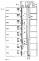
- FIGS. 1 and 2 show two different embodiments of an elevator installation 10 for the transport of persons / goods between floors 30.1 to 30.8 of a building 30 .
- the elevator installation 10 has at least one elevator, which elevator is advantageously installed in a shaft 31 of the building 30 .
- the person skilled in various options of variation in the installation of an elevator in a building 30 free.
- the shaft can only partially pass through the building 30 , or an elevator is installed without a box in a courtyard of the building 30 or outside the building 30 .
- the elevator has at least one cabin 2, 2 ' , which cabins 2, 2' as a single or double cabin in the vertical direction of travel advantageously on a pair of guide rails 5, 5 ' are moved.
- the cabins 2, 2 ' are conventional and proven elevator cars, which are moved over guide shoes on the guide rails 5, 5' .
- Each cabin has at least one car door 8, 8 ' , over which car doors 8, 8' persons / goods access to the car 2, 2 ' have ..
- the elevator installation 10 has a drive 6 , 6 ' per booth 2, 2' .
- traction sheave drives with traction sheaves, which connect the cabins 2, 2 ' via propellant 4, 4' with counterweights 3, 3 ' .
- the cabins 2, 2 ' and the counterweights 3, 3' are arranged in the representations according to FIGS. 1 and 2 in different planes.
- the propellant 4, 4 ' may have any shape, and it may be made of any materials. For example.
- the propellant 4, 4 ' is a round rope, double rope or a belt.
- the blowing agent 4, 4 ' at least partially made of steel or aramid fibers.
- the skilled person can use all known and proven drives 6, 6 ' .
- Gearless drives or those with gearboxes can be used.
- drives 6, 6 ' with permanent magnets, with synchronous motors, with asynchronous motors or with linear motors can be used.
- the drives 6, 6 ' can be arranged stationarily directly in the shaft 31 in a stationary manner in a separate machine room 32 or as shown in the embodiment according to FIG. 2 .
- the skilled person has knowledge of the present invention, free choice of the arrangement of the drives.
- the drives 6, 6 ' can be arranged as shown in the embodiment in the embodiment according to FIG. 1, at the upper end of guide rails 5, 5' at substantially the same height in the shaft 31 may be arranged.
- the drives need not be stationary, but they can also be mobile on the cabins or the counterweights.
- the drives 6, 6 ' are controlled by at least one drive control 16, 16' .
- a central stationary drive control 16 is provided for both drives 6, 6 ' with at least one arithmetic unit and at least one memory in the machine room 32 .
- a separate stationary drive control 16, 16 ' with at least one computing unit and at least one memory close to the shaft 31 is provided for each drive 6, 6' .
- At least one control program is stored in the memory, which control program is executed by the arithmetic unit.
- the drive control 16, 16 ' transmits drive control signals to the drives 6, 6' in order to accelerate or brake or at least hold them in accordance with a programmed travel curve.
- the drive control can also be arranged mobile on the cabins or counterweights.
- a central drive control or multiple drive controls for each cabin can / may be arranged so mobile.
- the elevator system 10 has at least one car position detection sensor 21, 21 ' for detecting the current absolute position of each of the cars 2 , 2' moved independently of each other in the shaft 31 .
- a coding is attached to a speed governor cable 12, 12 ' .
- Each cabin 2, 2 ' has a speed governor rope 12, 12' , which is arranged next to the car 2, 2 ' in the shaft 31 and mechanically fixed to the car 2, 2' .
- the up and down movement of the cars 2, 2 ' in the shaft 31 is thus transmitted to the speed governor rope 12, 12' .
- the distances in FIG. 1 between the cars 2, 2 ' and the speed governor cables 12, 12' are not to scale.
- Each speed limiter cable 12, 12 ' is mechanically connected to a speed limiter 14, 14' arranged in the engine room 32 .
- Speed limiter 14, 14 ' detects an overspeed of the car 2, 2' and triggers at overspeed at least one of the safety measures described below.
- a deflection roller 13, 13 ' arranged on the shaft bottom enables the return of the speed governor cable 12, 12'.
- the car position detecting sensor 21, 21 ' is mounted in the engine room 32 on the speed limiter 13, 13' .
- the car position detecting sensor 21, 21 ' may decode optical codings such as color codings or magnetic codings on the speed limiter cable 12, 12' .
- the decoding may be done by the car position detecting sensor 21, 21 ' or by the safety controller 26, 26' .
- the car position detection sensor 21, 21 ' can also be arranged in the shaft 31 .
- the person skilled in the art can also attach codings to the propellant 4, 4 ' of each car 2, 2' and to detect codings on the propellant 4, 4 ' by means of car position detection sensors 21, 21' .
- the person skilled in the speed limiter rope 12, 12 ' or on the propellant 4, 4' attach mechanical markings such as ball or hook, which are detected by correspondingly designed mechanical car position detection sensors 21, 21 ' .
- a marking is provided for a cable unit length of 10 cm. By counting the markings, the current position d of the cars 2, 2 ' can be determined with respect to a specific, known starting position. The counting of the markings can be done by the car position detecting sensor 21, 21 ' or by the safety controller 26, 26' .
- the skilled person can also define smaller or larger cable unit lengths.
- the car position detection sensor 21, 21 ' is a magnetic sensor mounted on the car 2, 2' , which magnetic sensor scans a coded magnetic tape 9 mounted in the shaft 31 with high resolution. Codes on the magnetic tape 9 are decoded into a current absolute position of the car 2, 2 ' . The decoding may be done by the car position detecting sensor 21, 21 ' or by the safety controller 26, 26' .
- a straight-line installation, for example, in addition to at least one guide rail 5, 5 ' allows a magnetic tape 9 to be used with a high information density.
- the car position detection sensor 21, 21 ' may also be an optical sensor mounted on the car 2, 2' which detects any pattern in the carousel 31 as car position data. In a calibration run, these patterns are captured and stored as primary cabin position data. During operation of the elevator installation 10 , currently detected cabin position data are compared with the stored primary cabin position data. The storage or comparison of cabin position data can be done by the car position detection sensor 21, 21 ' or by the safety controller 26, 26' . Also, those skilled in the art can attach mechanical markings such as balls or hooks in the well 31 which are detected by correspondingly designed mechanical car position detecting sensors 21, 21 ' . For example. are at least one guide rail 5, 5 ' every 10 cm a mark provided.
- the person skilled encodings can not over the entire length of the shaft mount 31 b zw. M n ot model ü over t he g eticiane L ength d S it chachts 31 capture or not on the entire length of the overspeed 12, 12 'or Attach propellant 4, 4 ' .
- the expert can attach codes or patterns only in such area of the shaft 31 or capture where an actual risk of collision of cabins 2, 2 ' in the shaft 31 or where an actual risk of collision of cabins 2, 2' with Shaft ends exists.
- the detection of the car position data advantageously takes place continuously, for example at regular intervals of 10 msec.
- Shaft doors / interlocks On each floor 30.0 to 30.8 , access to the shaft 34 takes place via shaft doors 11.0 to 11.8 .
- the shaft doors 11.0 to 11.8 can be single-sided or double-sided opening doors.
- the shaft doors 11.0 to 11.8 are preferably carried out complacent; that is, they close automatically as soon as they are not actively held open. In addition to closing the shaft doors 11.0 to 11.8 closed shaft doors are locked 11.0 to 11.8.
- each shaft door 11.0 to 11.8 on a lock 18.0 to 18.8 is self-coincident when the landing door 11.0 to 11.8 is closed.
- An active lock is not necessary.
- the latches 18.0 to 18.8 are preferably designed such that they can only be unlocked and opened or closed and locked by a car door 8, 8 ' provided on a car 2, 2' , or that they unlock with a special tool and postpone by hand.
- Lock position detection sensors Each shaft door 11.0 to 11.8 has at least one lock position detection sensor 20.0 to 20.8 .
- the lock position detection sensor 20.0 to 20.8 detects positions of the latches 18.0 to 18.8 of the landing doors 11.0 to 11.8.
- Locking position detection sensors 20.0 to 20.8 can be used by well-known and proven sensors such as locking device contacts, microswitches, inductive sensors such as radio frequency identification (RFID) sensors, capacitive sensors or optical sensors, etc., in elevator construction.
- RFID radio frequency identification
- the detection of the locking position data advantageously takes place continuously, for example at regular intervals of 10 msec.
- Safety control / data bus At least one safety control 26, 26 ' is provided which, as exemplified in FIGS. 3 and 4 , receives transmitted cabin position data determined by the car position detection sensors 21, 21' via a data bus 22 and interlock position data determined by the locking position detection sensors 20.0 to 20.8 which transmits via the data bus 22 to the drive control 16, 16 ' shaft area data.
- the safety controller 26, 26 ' advantageously has at least one arithmetic unit and at least one memory. At least one safety program is stored in the memory, which safety program is executed by the computer.
- the safety controller 26, 26 ' monitors whether safety-critical distances are exceeded. These distances are described in detail below. If a safety-critical distance is exceeded, predefined safety measures are initiated.
- a first security measure is the delaying of at least one drive 6, 6 ' .
- Another safety measure is emergency braking, ie the engagement of the holding brake of at least one drive 6 , 6 ' .
- Another safety measure is the collapse of at least one safety gear of the cabins 2, 2 '.
- the first and the better security measures can be staggered or triggered in combination. Thus, as a first security measure, a delay can be initiated. If the safety-critical distance continues to decrease, emergency braking can also be initiated as a further safety measure.
- a safety gear can additionally take place as a further safety measure.
- the person skilled in the art can also make other types of shutdown of the cabins 2, 2 '. So he can, for example, provide a cabin brake in the form of a disc brake. He may also provide a braking of the propellant.
- the data bus 22 is a known and proven signal bus. It can be a signal bus based on electrical - or optical Signal transmission, such as an Ethernet network, a token ring network, etc. It can also be a wireless network, an infrared network, a radar network, a beam network, etc.
- the transmission media like Two-wire, 230/400 VAC mains, radio, infrared, microwaves, fiber optics, internet, etc. can be chosen freely.
- the safety system thus consists of the components car position detection sensors 21, 21 ' , the lock position detection sensors 20.0 to 20.8 , safety controller 26, 26' and drive control 16, 16 ' , which communicate with each other via the data bus 22 .
- the components of the security system are advantageously bus modules.
- a bus module is an electronic card, with at least one data memory and at least one arithmetic unit.
- data bus 22 is a LON bus, where bus modules communicate easily with each other and are programmable.
- the LON bus is a technology that enables the creation of distributed networks using many simple bus nodes. In particular, a direct communication between the individual computing units of the components is possible.
- the LON bus protocol is the carrier of the control information and the individual computing units of the components can be controlled directly via the LON bus.
- the bus nodes can be programmed with logical links.
- the LON bus has a free topology and can be structured in lines, circles, trees, etc.
- the data bus 22 has, for example, a branche
- the car position detection sensors 21, 21 ' and locking position detection sensors 20.0 to 20.8 are jointly monitored by a central safety controller 26 .
- the central safety controller 26 transmits shaft area data to a central drive control 16 .
- each cabin 2, 2 ' has a safety circuit 26, 26' .
- a first car position detection sensor 21 of a first car 2 is monitored by a first safety controller 26 .
- a second car position detection sensor 21 'of a second car 2' is monitored by a second safety control 26 ' .
- the two safety controllers 26 , 26 ' mutually exchange detected cabin position data.
- the lock position detection sensors 20.0 to 20.8 are monitored by both safety controllers 26, 26 ' .
- the first safety controls 26 transmit shaft area data to the drive control 16 of the drive 6 of the first car 2 and the second safety controls 26 ' transmit shaft area data to the drive control 16' of the drive 6 'of the second car 2'.
- the data bus 22 thus enables two important functions, a rapid transmission of data and a request for the availability of the sensors of the security system.
- the safety controller 26, 26 ' is designed to evaluate the car position data or the locking position data in order to trigger one or more predefined reactions, in particular the detection and localization of an error, the initiation of a service call, the stoppage of a car 2, 2 ' or carrying out a different situation-adapted reaction when recognizing a dangerous mutual approach of the cabins 2 , 2' or the open standing of a shaft door 11.0 to 11.8.
- the safety controller 26, 26 ' is designed such that it evaluates the car position data or the locking position data in order to correct detected transmission errors by evaluating a plurality of data packets.
- the car doors 8, 8 ' are also monitored; As a result, by means of a coincidence test of the signals of the shaft doors 11.0 to 11.8 on the one hand and the car doors 8, 8 ', on the other hand, a statement about the functionality of the locking position detection sensors 20.0 to 20.8 attained.
- the safety controller 26, 26 ' evaluates the transmitted locking position data, for example, in such a way that it interrogates the locking position detection sensors 20.0 to 20.8 at periodic intervals of 20 ms. In this way, a communication interruption in the area of the data bus 22 or the bus node can thus be detected very quickly.
- each locking position detection sensor 20.0 to 20.8 periodically at greater time intervals, b spw. once within 8 or 2 4 hours.
- a test drive to this floor 30.0 to 30.8 is initiated by the safety controller 26, 26 'for test purposes (forced test).
- the execution of all tests is monitored by the safety controller 26, 26 'and entered into a table and stored.
- Safe shaft areas The safety control 26, 26 ' determined for the cars 2, 2' safe shaft areas in which the cabs, while maintaining a defined safety distance to a next car 2, 2 ' or the shaft end and with normal delay in the direction of travel of the car 2, 2 ' seen in a next floor stop retract and can hold there. Safe shaft areas are thus such shaft areas in which the cabins 2, 2 'can be moved without initiating further safety measures such as emergency braking, ie engagement of the holding brake or engagement of a safety gear. For this purpose, at least one travel curve is stored in the safety program, according to which the cars 2, 2 'are accelerated, braked or held by the drives 6, 6' .
- the travel curve has three areas, an acceleration area, where the cars 2, 2 ' are accelerated with predetermined normal acceleration, a speed area where the cars 2, 2' are moved at a predetermined normal speed and a braking area, where the cars 2, 2 ' be decelerated with a given normal deceleration.
- a normal acceleration or a normal deceleration is understood to be an acceleration or deceleration perceived by the persons as pleasant and acceptable.
- the safety program advantageously determines a safe manhole area in real time for each car 2, 2 ' .
- those skilled in the art may use other definitions of a safety margin. So he can, for example, use a stronger delay than the normal delay, he can also emergency braking, ie initiate a collapse of the holding brake.
Landscapes
- Elevator Control (AREA)
Abstract
Description
- Für zwei mit Normalgeschwindigkeit aufeinanderzufahrende Kabinen 2, 2' ist der Sicherheitsabstand gleich dem doppelten vollen Bremsweg bei Normalverzögerung.
- Fährt eine erste Kabine 2 mit Normalgeschwindigkeit auf eine stehende zweite Kabine 2' zu, so ist der Sicherheitsabstand gleich dem einfachen vollen Bremsweg bei Normalverzögerung.
- Fährt eine Kabine 2, 2' mit Normalgeschwindigkeit auf ein Schachtende bzw. gegen geöffnete Schachttüren 11.0 bis 11.8 zu, so ist der Sicherheitsabstand gleich dem einfachen vollen Bremsweg bei Normalverzögerung.
Claims (13)
- Sicherheitssystem für eine Aufzugsanlage (10) zum Transport von Personen / Gütern in einem Gebäude (30), mit mindestens zwei übereinander angeordneten Kabinen ( 2, 2'), welche Kabinen ( 2, 2') unabhängig voneinander in einem Schacht (31) verfahrbar sind, mit einem Antrieb (6, 6') für jede Kabine (2, 2'), mit mindestens einer Antriebssteuerung (16, 16') zum Ansteuern der Antriebe (6, 6'), und mit Kabinenpositionserfassungssensoren (21, 21') zum Erfassen der Positionen von jeder Kabine (2, 2'), dadurch gekennzeichnet, dass die Kabinenpositionserfassungssensoren (21, 21') Kabinenpositionsdaten an mindestens eine Sicherheitssteuerung (26, 26') übermitteln, dass Schachttüren (11.0 bis 11.8) Zugänge zum Schacht (31) verschliessen, dass Verriegelungen (18.0 bis 18.8) Schachttüren (11.0 bis 11.8) verriegeln, dass Verriegelungsstellungserfassungssensoren (20.0 bis 20.8) Stellungen der Verriegelungen (18.0 bis 18.8) erfassen, dass die Verriegelungsstellungserfassungssensoren (20.0 bis 20.8) Verriegelungsstellungsdaten an die Sicherheitssteuerung (26, 26') übermitteln, und dass die Sicherheitssteuerung (26, 26') aus den Kabinenpositionsdaten und den Verriegelungsstellungsdaten Schachtbereichsdaten mit Angaben zu Schachtbereichen, in denen jede Kabinen (2, 2') sicher verfahrbar ist ermittelt.
- Sicherheitssystem gemäss Anspruch 1, dadurch gekennzeichnet, dass die Sicherheitssteuerung (26, 26') die Schachtbereichsdaten an die Antriebssteuerung (16, 16') übermittelt, und dass die Antriebssteuerung (16, 16') die Schachtbereichsdaten in Antriebssteuersignale umsetzt.
- Sicherheitssystem gemäss Anspruch 2, dadurch gekennzeichnet, dass die Kabinenpositionserfassungssensoren (21, 21') Kabinenpositionsdaten und die Verriegelungsstellungserfassungssensoren (20.0 bis 20.8) Verriegelungsstellungsdaten über eine Datenbus (22) an die Sicherheitssteuerung (26, 26') übermitteln und/oder dass die Sicherheitssteuerung (26, 26') Schachtbereichsdaten über eine Datenbus (22) an die Antriebssteuerung (16,16') übermittelt.
- Sicherheitssystem gemäss Anspruch 3, dadurch gekennzeichnet, dass die Kabinenpositionserfassungssensoren (21, 21'), Kabinenpositionsdaten an eine zentrale Sicherheitssteuerung (26, 26') übermitteln, dass die Verriegelungsstellungserfassungssensoren (20.0 bis 20.8) Verriegelungsstellungsdaten an die zentrale Sicherheitssteuerung (26, 26') übermitteln, und dass die zentrale Sicherheitssteuerung (26, 26') Schachtbereichsdaten an eine zentrale Antriebssteuerung (16) für alle Kabinen (2, 2') übermittelt.
- Sicherheitssystem gemäss Anspruch 3, dadurch gekennzeichnet, dass ein Kabinenpositionserfassungssensor (21) einer ersten Kabine (2) Kabinenpositionsdaten an eine erste Sicherheitssteuerung (26) übermittelt, dass ein Kabinenpositionserfassungssensor (21') einer zweiten Kabine (2') Kabinenpositionsdaten an eine zweite Sicherheitssteuerung (26') übermittelt, und dass die beiden Sicherheitssteuerungen (26, 26') Kabinenpositionsdaten der beiden Kabinen (2, 2') gegenseitig austauschen.
- Sicherheitssystem gemäss Anspruch 5, dadurch gekennzeichnet, dass die Verriegelungsstellungserfassungssensoren (20.0 bis 20.8) Verriegelungsstellungsdaten an beide Sicherheitssteuerungen (26, 26') übermitteln, und/oder dass die erste Sicherheitssteuerung (26) Schachtbereichsdaten an eine erste Antriebssteuerung (16) zum Ansteuern eines Antriebes (6) der ersten Kabine (2) übermittelt, und dass die zweite Sicherheitssteuerung (26') Schachtbereichsdaten an eine zweite Antriebssteuerung (16') zum Ansteuern eines Antriebes (6') der zweiten Kabine (2') übermittelt.
- Sicherheitssystem gemäss einem der Ansprüche 1 bis 6, dadurch gekennzeichnet, dass die Kabinenpositionserfassungssensoren (21, 21') optische bzw. magnetische Sensoren sind, welche optische bzw. magnetische Kodierungen eines Geschwindigkeitsbegrenzerseils (12, 12') oder eines Treibmittels (4,4') erfassen oder dass die Kabinenpositionserfassungssensoren (21, 21') mechanische Sensoren sind, welche mechanische Markierungen eines Geschwindigkeitsbegrenzerseils (12, 12') oder eines Treibmittels (4, 4') erfassen oder dass die Kabinenpositionserfassungssensoren (21, 21') magnetische Sensoren sind, welche Kodierungen eines im Schacht (31) montierten Magnetbandes (9) erfassen oder dass die Kabinenpositionserfassungssensoren (21, 21') optische Sensoren sind, welche Muster im Schacht (31) erfassen oder dass die Kabinenpositionserfassungssensoren (21, 21') mechanische Sensoren sind, welche Markierungen im Schacht (31) erfassen.
- Verfahren zum Betrieb einer Aufzugsanlage (10) mit einem Sicherheitssystem zum Transport von Personen / Gütern in einem Gebäude (30), mit mindestens zwei übereinander angeordneten Kabinen (2, 2'), welche Kabinen (2, 2') unabhängig voneinander in einem Schacht (31) verfahrbar sind, mit einem Antrieb (6, 6') für jede Kabine (2, 2'), mit mindestens einer Antriebssteuerung (16, 16') zum Ansteuern der Antriebe (6, 6'), und mit Kabinenpositionserfassungssensoren (21, 21') zum Erfassen der Positionen von jeder Kabine (2, 2'), dadurch gekennzeichnet, dass Kabinenpositionsdaten an mindestens eine Sicherheitssteuerung (26, 26') übermittelt werden, dass Zugänge zum Schacht (31) durch Schachttüren (11.0 bis 11.8) verschlossen werden, d ass Schachttüren (11.0 bis 11.8) durch Verriegelungen (18.0 bis 18.8) verriegelt werden, dass Stellungen der Verriegelungen (18.0 bis 18.8) durch Verriegelungsstellungserfassungssensoren (20.0 bis 20.8) erfasst werden, dass Verriegelungsstellungsdaten an die Sicherheitssteuerung (26, 26') übermittelt werden, und dass aus den Kabinenpositionsdaten und den Verriegelungsstellungsdaten Schachtbereichsdaten mit Angaben zu Schachtbereichen, in denen jede Kabinen (2, 2') sicher verfahrbar ist ermittelt werden.
- Verfahren gemäss Anspruch 8, dadurch gekennzeichnet, dass die Schachtbereichsdaten an die Antriebssteuerung (16, 16') übermittelt werden, und dass die Schachtbereichsdaten von der Antriebssteuerung (16, 16') in Antriebssteuersignale umgesetzt werden.
- Verfahren gemäss Anspruch 9, dadurch gekennzeichnet, dass die Kabinen (2, 2') mit Schachtbereichsdaten in sicheren Schachtbereichen verfahren werden, in denen die Kabine (2, 2') unter Bewahrung eines Sicherheitsabstandes zu einer nächsten Kabine (2, 2') bzw. zum Schachtende und mit Normalverzögerung in Fahrtrichtung der Kabine (2, 2') gesehen in einen nächsten Stockwerkhalt einfahren und dort halten kann.
- Verfahren gemäss Anspruch 9 oder 10, dadurch gekennzeichnet, dass die Kabinen (2, 2') mit einem Sicherheitsabstand der gleich dem gesamten Bremsweg der Kabinen (2, 2') bei Normalverzögerung ist verfahren werden.
- Verfahren gemäss einem der Ansprüche 9 bis 11, dadurch gekennzeichnet, dass eine Verfügbarkeit der Kabinenpositionserfassungssensoren (21, 21') und der Verriegelungsstellungserfassungssensoren (20.0 bis 20.8) von der Sicherheitssteuerung (26, 26') über eine Datenbus (22) überprüft wird.
- Verfahren gemäss einem der Ansprüche 9 bis 12, dadurch gekennzeichnet, dass beim Überschreiten eines sicherheitskritischen Abstandes als erste Sicherheitsmassnahme mindestens ein Antrieb (6, 6') verzögert wird und/oder dass als weitere Sicherheitsmassnahme mindestens ein Antrieb (6, 6') notgebremst wird und/oder dass als weitere Sicherheitsmassnahme mindestens einer Fangvorrichtung der Kabinen (2, 2') einfällt.
Priority Applications (1)
| Application Number | Priority Date | Filing Date | Title |
|---|---|---|---|
| EP20040024136 EP1526104B1 (de) | 2003-10-20 | 2004-10-09 | Sicherheitssystem für eine Aufzugsanlage mit mehreren Kabinen |
Applications Claiming Priority (3)
| Application Number | Priority Date | Filing Date | Title |
|---|---|---|---|
| EP03405757 | 2003-10-20 | ||
| EP03405757 | 2003-10-20 | ||
| EP20040024136 EP1526104B1 (de) | 2003-10-20 | 2004-10-09 | Sicherheitssystem für eine Aufzugsanlage mit mehreren Kabinen |
Publications (2)
| Publication Number | Publication Date |
|---|---|
| EP1526104A1 true EP1526104A1 (de) | 2005-04-27 |
| EP1526104B1 EP1526104B1 (de) | 2006-06-07 |
Family
ID=34395308
Family Applications (1)
| Application Number | Title | Priority Date | Filing Date |
|---|---|---|---|
| EP20040024136 Expired - Lifetime EP1526104B1 (de) | 2003-10-20 | 2004-10-09 | Sicherheitssystem für eine Aufzugsanlage mit mehreren Kabinen |
Country Status (1)
| Country | Link |
|---|---|
| EP (1) | EP1526104B1 (de) |
Cited By (1)
| Publication number | Priority date | Publication date | Assignee | Title |
|---|---|---|---|---|
| WO2009080478A1 (de) * | 2007-12-21 | 2009-07-02 | Inventio Ag | Aufzugssystem mit abstandskontrolle |
Families Citing this family (4)
| Publication number | Priority date | Publication date | Assignee | Title |
|---|---|---|---|---|
| US7353914B2 (en) * | 2003-10-20 | 2008-04-08 | Inventio Ag | Safety system for an elevator |
| ZA200710597B (en) † | 2006-12-21 | 2008-11-26 | Inventio Ag | Method of preventing collision of two lift cages movable in the same shaft of a lift installation and corresponding lift installation |
| WO2009070143A1 (en) | 2007-11-30 | 2009-06-04 | Otis Elevator Company | Coordination of multiple elevator cars in a hoistway |
| US10745243B2 (en) | 2014-10-21 | 2020-08-18 | Inventio Ag | Elevator comprising a decentralized electronic safety system |
Citations (4)
| Publication number | Priority date | Publication date | Assignee | Title |
|---|---|---|---|---|
| US5419414A (en) * | 1993-11-18 | 1995-05-30 | Sakita; Masami | Elevator system with multiple cars in the same hoistway |
| US6161652A (en) * | 1998-02-02 | 2000-12-19 | Inventio Ag | Method and apparatus for controlling elevator cars in a common sling |
| EP1357075A1 (de) * | 2000-11-08 | 2003-10-29 | Mitsubishi Denki Kabushiki Kaisha | Kabine-einrichtung für doppeldeckaufzüge |
| EP1371596A1 (de) * | 1995-10-17 | 2003-12-17 | Inventio Ag | Sicherheitseinrichtung für eine Aufzugsgruppe |
-
2004
- 2004-10-09 EP EP20040024136 patent/EP1526104B1/de not_active Expired - Lifetime
Patent Citations (4)
| Publication number | Priority date | Publication date | Assignee | Title |
|---|---|---|---|---|
| US5419414A (en) * | 1993-11-18 | 1995-05-30 | Sakita; Masami | Elevator system with multiple cars in the same hoistway |
| EP1371596A1 (de) * | 1995-10-17 | 2003-12-17 | Inventio Ag | Sicherheitseinrichtung für eine Aufzugsgruppe |
| US6161652A (en) * | 1998-02-02 | 2000-12-19 | Inventio Ag | Method and apparatus for controlling elevator cars in a common sling |
| EP1357075A1 (de) * | 2000-11-08 | 2003-10-29 | Mitsubishi Denki Kabushiki Kaisha | Kabine-einrichtung für doppeldeckaufzüge |
Cited By (2)
| Publication number | Priority date | Publication date | Assignee | Title |
|---|---|---|---|---|
| WO2009080478A1 (de) * | 2007-12-21 | 2009-07-02 | Inventio Ag | Aufzugssystem mit abstandskontrolle |
| US8439167B2 (en) | 2007-12-21 | 2013-05-14 | Inventio Ag | Spacing control for two elevator cars in a common shaft |
Also Published As
| Publication number | Publication date |
|---|---|
| EP1526104B1 (de) | 2006-06-07 |
Similar Documents
| Publication | Publication Date | Title |
|---|---|---|
| CN100336710C (zh) | 电梯设备的安全系统和具安全系统的电梯设备的工作方法 | |
| EP2022742B1 (de) | Aufzugsystem | |
| EP1401757B2 (de) | Verfahren zum verhindern einer unzulässig hohen fahrgeschwindigkeit des lastaufnahmemittels eines aufzugs | |
| EP1371596B1 (de) | Sicherheitseinrichtung für eine Aufzugsgruppe | |
| DE112009004592B4 (de) | Aufzuganlage und Verfahren zum Überprüfen derselben | |
| EP1490284B1 (de) | Schachtüberwachungssystem für aufzug | |
| DE60004501T2 (de) | Aufzugsrettungssystem | |
| DE112013007449T5 (de) | Aufzugvorrichtung | |
| EP2250115B1 (de) | Rolltreppe oder rollsteig | |
| EP1404603B1 (de) | Aufzuganlage mit virtueller schutzzone am schachtfuss und/oder am schachtkopf und verfahren zum ansteuern derselben | |
| EP3599208A1 (de) | Aufzuganlage mit einer mehrzahl von fahrkörben sowie einem dezentralen sicherheitssystem | |
| WO2009074627A1 (de) | Aufzugssystem mit vertikal und horizontal verfahrbaren aufzugkabinen | |
| WO2013072184A1 (de) | Aufzug mit sicherheitseinrichtung | |
| DE102015111754A1 (de) | Verfahren und Einrichtung zum Schließen von Türen eines Aufzuges | |
| EP3347295B1 (de) | Personentransportanlage mit einer einrichtung zur betriebszustandsbestimmung | |
| EP2457860B1 (de) | Sicherheitseinrichtung für einen Aufzug | |
| DE102019207265A1 (de) | Bereichsobjekterfassungssystem für ein aufzugsystem | |
| DE60019520T2 (de) | Zwangsgeführtes Nahverkehrssystem | |
| EP4267503A1 (de) | Aufzug, verfahren zur steuerung eines aufzuges | |
| EP1526104B1 (de) | Sicherheitssystem für eine Aufzugsanlage mit mehreren Kabinen | |
| DE112006000498T5 (de) | Aufzuganlage | |
| EP3744673B1 (de) | Verfahren zur absicherung einer aufzugskabine mittels einer temporären entriegelungszone | |
| EP4214149B1 (de) | Sicherheitsvorrichtung zum steuern sicherheitsrelevanter ucm- und udm-funktionen in einer aufzuganlage | |
| DE3788081T2 (de) | Bremseinrichtung für Hebemittel wie Personen- oder Lastenaufzüge. | |
| DE102024129825A1 (de) | Verfahren zum Betreiben einer Aufzugsanlage mit Notbremsvorrichtungen |
Legal Events
| Date | Code | Title | Description |
|---|---|---|---|
| PUAI | Public reference made under article 153(3) epc to a published international application that has entered the european phase |
Free format text: ORIGINAL CODE: 0009012 |
|
| AK | Designated contracting states |
Kind code of ref document: A1 Designated state(s): AT BE BG CH CY CZ DE DK EE ES FI FR GB GR HU IE IT LI LU MC NL PL PT RO SE SI SK TR |
|
| AX | Request for extension of the european patent |
Extension state: AL HR LT LV MK |
|
| 17P | Request for examination filed |
Effective date: 20051005 |
|
| GRAP | Despatch of communication of intention to grant a patent |
Free format text: ORIGINAL CODE: EPIDOSNIGR1 |
|
| AKX | Designation fees paid |
Designated state(s): CH DE FR GB LI |
|
| REG | Reference to a national code |
Ref country code: HK Ref legal event code: DE Ref document number: 1076622 Country of ref document: HK |
|
| GRAS | Grant fee paid |
Free format text: ORIGINAL CODE: EPIDOSNIGR3 |
|
| GRAA | (expected) grant |
Free format text: ORIGINAL CODE: 0009210 |
|
| AK | Designated contracting states |
Kind code of ref document: B1 Designated state(s): CH DE FR GB LI |
|
| REG | Reference to a national code |
Ref country code: GB Ref legal event code: FG4D Free format text: NOT ENGLISH |
|
| REG | Reference to a national code |
Ref country code: CH Ref legal event code: EP |
|
| REF | Corresponds to: |
Ref document number: 502004000698 Country of ref document: DE Date of ref document: 20060720 Kind code of ref document: P |
|
| GBT | Gb: translation of ep patent filed (gb section 77(6)(a)/1977) |
Effective date: 20060724 |
|
| REG | Reference to a national code |
Ref country code: HK Ref legal event code: GR Ref document number: 1076622 Country of ref document: HK |
|
| ET | Fr: translation filed | ||
| PLBE | No opposition filed within time limit |
Free format text: ORIGINAL CODE: 0009261 |
|
| STAA | Information on the status of an ep patent application or granted ep patent |
Free format text: STATUS: NO OPPOSITION FILED WITHIN TIME LIMIT |
|
| 26N | No opposition filed |
Effective date: 20070308 |
|
| PGFP | Annual fee paid to national office [announced via postgrant information from national office to epo] |
Ref country code: FR Payment date: 20121031 Year of fee payment: 9 Ref country code: CH Payment date: 20121030 Year of fee payment: 9 |
|
| PGFP | Annual fee paid to national office [announced via postgrant information from national office to epo] |
Ref country code: GB Payment date: 20121019 Year of fee payment: 9 |
|
| REG | Reference to a national code |
Ref country code: CH Ref legal event code: PL |
|
| GBPC | Gb: european patent ceased through non-payment of renewal fee |
Effective date: 20131009 |
|
| PG25 | Lapsed in a contracting state [announced via postgrant information from national office to epo] |
Ref country code: LI Free format text: LAPSE BECAUSE OF NON-PAYMENT OF DUE FEES Effective date: 20131031 Ref country code: GB Free format text: LAPSE BECAUSE OF NON-PAYMENT OF DUE FEES Effective date: 20131009 Ref country code: CH Free format text: LAPSE BECAUSE OF NON-PAYMENT OF DUE FEES Effective date: 20131031 |
|
| REG | Reference to a national code |
Ref country code: FR Ref legal event code: ST Effective date: 20140630 |
|
| PG25 | Lapsed in a contracting state [announced via postgrant information from national office to epo] |
Ref country code: FR Free format text: LAPSE BECAUSE OF NON-PAYMENT OF DUE FEES Effective date: 20131031 |
|
| REG | Reference to a national code |
Ref country code: DE Ref legal event code: R084 Ref document number: 502004000698 Country of ref document: DE |
|
| PGFP | Annual fee paid to national office [announced via postgrant information from national office to epo] |
Ref country code: DE Payment date: 20231027 Year of fee payment: 20 |
|
| REG | Reference to a national code |
Ref country code: DE Ref legal event code: R071 Ref document number: 502004000698 Country of ref document: DE |