EP1526059B1 - Lenkstockmodul - Google Patents
Lenkstockmodul Download PDFInfo
- Publication number
- EP1526059B1 EP1526059B1 EP04104876A EP04104876A EP1526059B1 EP 1526059 B1 EP1526059 B1 EP 1526059B1 EP 04104876 A EP04104876 A EP 04104876A EP 04104876 A EP04104876 A EP 04104876A EP 1526059 B1 EP1526059 B1 EP 1526059B1
- Authority
- EP
- European Patent Office
- Prior art keywords
- rotor
- steering column
- locking ring
- module part
- stationary
- Prior art date
- Legal status (The legal status is an assumption and is not a legal conclusion. Google has not performed a legal analysis and makes no representation as to the accuracy of the status listed.)
- Expired - Lifetime
Links
- 230000033001 locomotion Effects 0.000 description 6
- 238000011161 development Methods 0.000 description 2
- 230000018109 developmental process Effects 0.000 description 2
- 230000015572 biosynthetic process Effects 0.000 description 1
- 230000000903 blocking effect Effects 0.000 description 1
- 230000009977 dual effect Effects 0.000 description 1
- 239000000314 lubricant Substances 0.000 description 1
- 230000002028 premature Effects 0.000 description 1
Images

Classifications
-
- B—PERFORMING OPERATIONS; TRANSPORTING
- B62—LAND VEHICLES FOR TRAVELLING OTHERWISE THAN ON RAILS
- B62D—MOTOR VEHICLES; TRAILERS
- B62D1/00—Steering controls, i.e. means for initiating a change of direction of the vehicle
- B62D1/02—Steering controls, i.e. means for initiating a change of direction of the vehicle vehicle-mounted
- B62D1/16—Steering columns
Definitions
- the invention relates to a steering column module having a stationary module part to be fastened to a jacket tube and a rotatable rotor driven by a steering spindle, the rotor being mounted with radial play in or on the stationary module part
- Steering stick modules are known in a variety. These steering column modules usually carry the steering column switch and can be provided with a receiving space for a clock spring, with which electrical data is transmitted from the fixed part of the vehicle to the rotating steering wheel. In addition, the steering column module can still be provided with a steering angle sensor, with which the position of the steering wheel is determined.
- This steering column module which has a stationary module part and a rotating rotor, is fastened to the jacket tube of the steering column, so that the stationary module part is stationary. In this case, the steering column spindle passes through the steering column module, so that the steering wheel can be placed on the free end of the steering column spindle. When attaching the steering column module to the jacket tube, care must be taken that the steering column module is as accurately as possible.
- the rotor has an axial clearance relative to the stationary module part, so that the rotor can follow a tumbling motion of the steering spindle. If such a steering column module is mounted, then it can not be ensured until the assembly of the steering wheel that the rotor retains its coaxial position relative to the steering column spindle. After placing the steering column module on the jacket tube and the steering column spindle, it often happens that the rotor slips before the steering wheel was attached, and then arranged offset to the steering skewer. Due to the offset, there may be disturbing noises, possibly even premature failure due to inadmissibly high wear.
- a steering column module with a fixed to a steering shaft stationary module part, which has a rotor and a rotor coupled to the return cam for a turn signal device.
- the reset cam is in this case arranged on an annular collar element, which in turn is rigidly coupled to the rotor.
- the collar member In order to allow a radially positionally correct attachment of the collar member on the rotor, the collar member of different size mounting projections, which cooperate with appropriately arranged recordings in the rotor and allow attachment of the collar member on the rotor only in a single radial angular position.
- the rotor can be locked without play with the stationary module part via a locking ring.
- the invention is therefore the object of a steering column module of the type mentioned in such a way that its attachment to the steering column spindle is less tolerant.
- the locking ring is mounted in the radial direction without play in the rotor or on the steering shaft, it is ensured that not only the stationary module part relative to the jacket tube, but also the rotor relative to the steering shaft is aligned exactly. Already when sliding the steering column module on the jacket tube and the end of the steering spindle, the automatic alignment of the steering column module. Adjustments are therefore no longer required.
- the locking ring secures the rotor in its locking position relative to the stationary module part against rotation.
- This has the advantage that the coil spring bel dispose their laying within the steering column module and no separate Vermosstcherungen longer required.
- This anti-rotation device acts as long as the locking ring is in its locking position.
- the locking ring When removing an already mounted steering wheel, the locking ring again assumes its locking position, so that in this way the rotor is again rotated relative to the stationary module part.
- the locking ring has a dual function, since it provides for the central orientation of the rotor and for blocking the rotation with the steering wheel removed.
- the locking ring has at least one finger which has a radially projecting nose, which engages in the locking position of the locking ring in a radial opening in the stationary module part.
- This radially projecting nose may be provided with the basement surface, with which the locking ring and the rotor are aligned with respect to the stationary module part.
- the nose can also act as anti-rotation. For this purpose, it engages in the locking position of the locking ring in an axial recess of the stationary module part, from which it is lifted when inserting the locking ring, which takes place when placing the steering wheel. As a result, the rotation is achieved.
- a special bearing of the rotor with respect to the stationary module part with which a tumbling motion of the rotor without the formation of disturbing noises is made possible, is created by the fact that the rotor is mounted on a blade-shaped support or a plurality of knobs on an axial surface of the stationary module part. It can be used for the bearing surface or the cutting edge or the studs a suitable for storage plastic or can be used in this area of the bearing a suitable lubricant. In any case, a wobbling movement of the rotor relative to the stationary module part does not generate a disturbing noise.
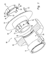
- the FIG. 1 shows a total of 10 designated steering column module, which, as in FIG. 3 dargesteilt, with a clamp 12 is attached to the upper end of a casing tube 14 of a steering column is.
- the steering column module 10 has a stationary module part 18, a rotor 20 and a locking ring 22.
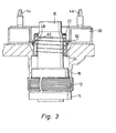
- the stationary module part 18 has, as in the FIG. 3 shown, at its lower end a ball joint, so that the steering column module 10 with respect to the casing tube 14 and the steering shaft 16 aligned, ie can be centered.
- bearing bush 24 of the stationary module part 18 has a bearing receptacle 26 which has an inwardly projecting collar 28 at its upper end.
- This collar 28 has an inner diameter which corresponds to the distance of outer surfaces 30 of opposite fingers 32 of the locking ring 22. This outer surface 30 is then overlapped by lugs 34. These lugs 34 engage in radial recesses 36, which are also provided on the collar 28.
- the locking ring 22 is received by the bearing bush 24, as is apparent from the Figures 3 and 4 is apparent.
- the fingers 32 reach through radial openings 38 and are supported inwardly by guide rails 40.
- the stationary module part 18 and the receiving space for a clock spring, not shown, is closed at the top of a rotor disk 42, as clearly in the Figures 3 and 4 is shown.
- This rotor disc 42 has two upwardly projecting axially pins 44 which engage in a steering wheel 46, so that by turning the steering wheel 46, the pins and thus the rotor disk 42 or the entire rotor 20 is rotated.
- the steering wheel 46 is not yet placed and the locking ring 22 assumes its locking position, in which it is held by a coil spring 48.
- the coil spring 48 is mounted in the bearing bush 24 and engages the upper end of the locking ring 22.
- a wedge surface 50 of each finger 32 which delimits the outer surface 30 abuts against a wedge counter surface 52 which is provided on a shoulder 54 of the bearing bush 24.
- the locking ring 22 is centered within the collar 28 by abutment of the fingers 32 with their outer surfaces 30 relative to the stationary module portion 18. In this way, the rotor 20 is aligned by means of the locking ring 22 coaxial with the stationary module part 18.
- the steering wheel 46 mounted on the free end of the steering shaft 16 presses a hub 56 of the steering wheel 46, the locking ring 22 against the force of the coil spring 48 axially into the bearing bushing 24 and lifts the wedge surface 50 of the fingers 32 of the wedge counter surface 52 of Shoulder 54 off, as in FIG. 5 shown.
- the rotor 20 is released from the stationary module part 18 and can move in the radial direction within the play 58 with respect to the stationary module part 18.
- the lugs 34 are excavated axially from the recesses 36, whereby the rotation of the rotor 20 with respect to the stationary module part 18 is also canceled.
- a blade-shaped bearing 60 can be seen, which is supported on an axial surface 62 of the stationary module part 18.
- a plurality of nubs may be provided, which take over the support of the rotor 20. Since the bearing 60 can be easily moved on the axial surface 62, no disturbing noises are generated. The rotor 20 can thus follow a possible wobbling movement of the steering spindle 16 and perform radial relative movements with respect to the stationary module part 18.
- the locking ring 22 Since the locking ring 22 by the coil spring 48 in the direction of his, in the FIG. 3 shown locking position is spring loaded, the locking ring 22 takes on release of the steering wheel 46 of the steering shaft 16 immediately his locking position automatically and centered the rotor 20 with respect to the stationary module part 18 and secures the rotor 20 against rotation.
Landscapes
- Engineering & Computer Science (AREA)
- Chemical & Material Sciences (AREA)
- Combustion & Propulsion (AREA)
- Transportation (AREA)
- Mechanical Engineering (AREA)
- Steering Controls (AREA)
- Lock And Its Accessories (AREA)
- Air Bags (AREA)
Description
- Die Erfindung betrifft ein Lenkstockmodul mit einem an einem Mantelrohr zu befestigenden stationären Modulteil und einem mittels einerLenkspindel angetriebenen drehbaren Rotor, wobei der Rotor mit radialem Spiel im oder am stationären Modulteil gelagert ist
- Lenkstockmodule sind in einer Vielzahl bekannt. Diese Lenkstockmodule tragen In der Regel die Lenkstockschalter und können mit einem Aufnahmeraum für eine Wickelfeder versehen sein, mit welcher elektrische Daten vom feststehenden Teil des Fahrzeugs auf das sich drehende Lenkrad übertragen werden. Außerdem kann das Lenkstockmodul noch mit einem Lenkwinkelsensor versehen sein, mit dem die Position des Lenkrades bestimmt wird. DiesesLenkstockmodul, welches einen stationären Modulteil und einen sich drehenden Rotor aufweist, wird am Mantelrohr der Lenksäule befestigt, so dass der stationäre Modulteil ortsfest ist. Dabei durchgreift die Lenkstockspindel das Lenkstockmodul, so dass auf das freie Ende der Lenkstockspindel das Lenkrad aufgesetzt werden kann. Beim Befestigen des Lenkstockmoduls am Mantelrohr muss darauf geachtet werden, dass das Lenkstockmodul möglichst genau d.h. koaxial zur Lenkstockspindel ausgerichtet ist, so dass sich beim Drehen des Lenkrads, wobei sich dadurch auch die Lenkstockspindel dreht, keine störenden Geräusche erzeugt werden. Da die Lenkstockspindel oftmals aufgrund eines radialen Seitenschlags eine Taumelbewegung durchführt, Ist es äußerst wichtig, dass das Lenkstockmodul möglichst zentriert zur Lenkstockspindel ausgerichtet ist.
- Üblicherweise besitzt der Rotor ein axiales Spiel gegenüber dem stationären Modulteil, so dass der Rotor einer Taumelbewegung der Lenkspindel folgen kann. Wird ein derartiges Lenkstockmodul montiert, dann kann bis zur Montage des Lenkrads nicht sichergestellt werden, dass der Rotor seine koaxiale Lage bezüglich der Lenkstockspindel beibehält. Nach dem Aufsetzen des Lenkstockmoduls auf das Mantelrohr und die Lenkstockspindel kommt es oftmals vor, dass der Rotor verrutscht, bevor das Lenkrad befestigt wurde, und dann versetzt zur Lenksteckspindel angeordnet ist. Aufgrund des Versatzes kann es zu störenden Geräuschen kommen, eventuell sogar zu einem vorzeitigen Ausfall wegen unzulässig hohem Verschleiß.
Aus derEP 1065107 A2 ist ein Lenkstockmodul mit einem an einer Lenkwelle befestigbaren stationären Modulteil, welches einen Rotor und einen mit dem Rotor gekoppelten Rückstellnocken für eine Blinkereinrichtung aufweist. Der Rückstellnocken ist hierbei an einem ringförmigen Kragenelement angeordnet, welches wiederum mit dem Rotor starr koppelbar ist. Um eine radial lagerichtige Befestigung des Kragenelements am Rotor zu ermöglichen weist das Kragenelement unterschiedlich große Befestigungsvorsprünge auf, die mit entsprechend angeordneten Aufnahmen im Rotor zusammenwirken und eine Befestigung des Kragenelements am Rotor nur in einer einzigen radialen Winkellage ermöglichen. Dabei ist der Rotor über einen Verriegelungsring spielfrei mit dem stationären Modulteil verriegelbar. - Der Erfindung liegt daher die Aufgabe zugrunde, ein Lenkstockmodul der eingangs genannten Art derart auszugestalten, dass dessen Befestigung an der Lenkstockspindel weniger toleranzbehaftet ist.
- Diese Aufgabe wird mit einem Lenkstockmodul mit den Merkmalen des Anspruchs 1 gelöst. Vorteilhafte Weiterbildungen sind in den Unteransprüchen anzugeben.
- Dadurch, dass der Verriegelungsring In radialer Richtung spielfrei im Rotor oder an der Lenkspindel gelagert ist, ist sichergestellt, dass nicht nur das stationäre Modulteil gegenüber dem Mantelrohr, sondern auch der Rotor gegenüber der Lenkspindel exakt ausgerichtet ist. Schon beim Aufschieben des Lenkstockmoduls auf das Mantelrohr und das Ende der Lenkspindel erfolgt die automatische Ausrichtung des Lenkstockmoduls. Justierarbeiten sind daher nicht mehr erforderlich.
- Bei einer Variante ist vorgesehen, dass der Verriegelungsring In seiner Verriegelungslage den Rotor gegenüber dem stationären Modulteil gegen Verdrehen sichert. Dies hat den Vorteil, dass die Wickelfeder ihre Lege Innerhalb des Lenkstockmoduls belbehält und keine gesonderten Verdrehstcherungen mehr erforderlich sind. Diese Verdrehsicherung wirkt so lange, wie sich der Verriegelungsring In seiner Verriegelungslage befindet. Beim Abnehmen eines bereits montierten Lenkrads nimmt der Verriegelungsring wieder seine Verriegelungslage ein, so dass hierdurch der Rotor wieder gegenüber dem stationären Modulteil verdrehgeslchert ist. Somit besitzt der Verriegelungsring eine Doppelfunktion, da er für die zentrale Ausrichtung des Rotors und für die Blockierung der Verdrehung bei abgenommenem Lenkrad sorgt.
- Bei einer Weiterbildung ist vorgesehen, dass der Verriegelungsring wenigstens einen Finger aufweist, der eine radial abstehende Nase besitzt, die in der Verriegelungslage des Verriegelungsrings in einen radialen Durchbruch im stationären Modulteil eingreift. Diese radial abstehende Nase kann mit der Kellfläche versehen sein, mit der der Verriegelungsring und der Rotorbezüglich des stationären Modulteils ausgerichtet werden. Die Nase kann aber auch als Verdrehsicherung wirken. Hierfür greift sie in der Verriegelungslage des Verriegelungsrings in eine axiale Ausnehmung des stationären Modulteils ein, aus der sie beim Einschieben des Verriegelungsrings, was beim Aufsetzen des Lenkrads erfolgt, ausgehoben wird. Dadurch wird die Verdrehsicherung gelöst.
- Eine spezielle Lagerung des Rotors bezüglich des stationären Modulteils, mit dem eine Taumelbewegung des Rotors ohne die Bildung von störenden Geräuschen ermöglicht wird, wird dadurch geschaffen, dass der Rotor über eine schneidenförmige Abstützung oder über mehrere Noppen auf einer Axialfläche des stationären Modulteils gelagert ist. Dabei kann für die Lagerfläche beziehungsweise die Schneide oder die Noppen ein für Lagerungen geeigneter Kunststoff verwendet werden beziehungsweise kann in diesem Bereich des Lagers ein geeigneter Schmierstoff eingesetzt werden. Auf jeden Fall erzeugt eine Taumelbewegung des Rotors gegenüber dem stationären Modulteil kein störendes Geräusch.
- Weitere Vorteile, Merkmale und Einzelheiten der Erfindung ergeben sich aus den Unteransprüchen sowie der nachfolgenden Beschreibung, in der unter Bezugnahme auf die Zeichnung ein besonders bevorzugtes Ausführungsbeispiel im Einzelnen beschrieben ist. Dabei können die in der Zeichnung dargestellten und in der Beschreibung sowie in den Ansprüchen erwähnten Merkmale jeweils einzeln für sich oder in beliebiger Kombination erfindungswesentlich sein.
- In der Zeichnung zeigen:
- Figur 1
- eine Explosionsdarstellung, teilweise aufge- schnitten, eines Ausführungsbelspiels des erfidungsgemäßen Lenkstockmoduls;
- Figur 2
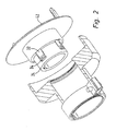
- die Ansicht gemäß
Figur 1 mit in den Rotor eingeschobenem Verriegelungsring; - Figur 3
- einen Längsschnitt durch das obere Ende ei- ner Lenksäule sowie das Lenkstockmodul;
- Figur 4
- eine Ansicht gemäß
Figur 3 mit aufgesetztem Lenkrad und entriegeltern Lenkstockmodul; und - Figur 5
- eine vergrößerte Wiedergabe des Aus- schnitts V gemäß
Figur 4 . - Die
Figur 1 zeigt ein Insgesamt mit 10 bezeichnetes Lenkstockmodul, welches, wie inFigur 3 dargesteilt, mit einer Schelle 12 an das obere Ende eines Mantelrohrs 14 einer Lenksäule befestigt Ist. Das Lenkstockmodul 10 weist einen stationären Modulteil 18, einen Rotor 20 und einen Verriegelungsring 22 auf. Der stationäre Modulteil 18 besitzt, wie in derFigur 3 dargestellt, an seinem unteren Ende ein Kugelgelenk, so dass das Lenkstockmodul 10 bezüglich des Mantelrohrs 14 und der Lenkspindel 16 ausgerichtet, d.h. zentriert werden kann. Zur Aufnahme einer am Rotor 20 nach unten abragenden Lagerbüchse 24 besitzt der stationäre Modulteil 18 eine Lageraufnahme 26, die an ihrem oberen Ende einen nach Innen vorspringenden Kragen 28 aufweist. - Dieser Kragen 28 weist einen Innendurchmesser auf, der dem Abstand von Außenoberflächen 30 von einander gegenüberliegenden Fingern 32 des Verriegelungsrings 22 entspricht. Diese Außenoberfläche 30 wird dann noch von Nasen 34 übergriffen. Diese Nasen 34 rasten in radiale Ausnehmungen 36 ein, die ebenfalls am Kragen 28 vorgesehen sind. Der Verriegelungsring 22 wird von der Lagerbüchse 24 aufgenommen, wie es aus den
Figuren 3 und4 ersichtlich ist. Dabei durchgreifen die Finger 32 radiale Durchbrüche 38 und werden nach innen von Führungsleisten 40 abgestützt. - Der stationäre Modulteil 18 und der Aufnahmeraum für eine nicht dargestellte Wickelfeder wird nach oben von einer Rotorscheibe 42 abgeschlossen, wie es deutlich in den
Figuren 3 und4 dargestellt ist. Diese Rotorscheibe 42 weist zwei nach oben axial abragende Zapfen 44 auf, die in ein Lenkrad 46 eingreifen, so dass durch Drehen des Lenkrads 46 die Zapfen und somit die Rotorscheibe 42 beziehungsweise der gesamte Rotor 20 in Drehung versetzt wird. - In der
Figur 3 ist das Lenkrad 46 noch nicht aufgesetzt und der Verriegelungsring 22 nimmt seine Verriegelungslage ein, in welcher er von einer Wendelfeder 48 gehalten wird. Die Wendelfeder 48 ist in der Lagerbüchse 24 gelagert und greift am oberen Ende des Verriegelungsrings 22 an. Dabei liegt eine die Außenoberfläche 30 nach oben begrenzende Keilfläche 50 eines jeden Fingers 32 an einer Keilgegenfläche 52 an, die an einer Schulter 54 der Lagerbüchse 24 vorgesehen ist. Außerdem wird der Verriegelungsring 22 innerhalb des Kragens 28 durch Anlage der Finger 32 mit ihren Außenoberflächen 30 bezüglich des stationären Modulteils 18 zentriert. Auf diese Weise wird der Rotor 20 mittels des Verriegelungsrings 22 koaxial zum stationären Modulteil 18 ausgerichtet. - Wird, wie in
Figur 4 dargestellt, das Lenkrad 46 auf das freie Ende der Lenkspindel 16 aufgesetzt, dann drückt eine Nabe 56 des Lenkrads 46 den Verriegelungsring 22 entgegen der Kraft der Wendelfeder 48 axial in die Lagerbüchse 24 ein und hebt die Keilfläche 50 der Finger 32 von der Keilgegenfläche 52 der Schulter 54 ab, wie inFigur 5 dargestellt. Dadurch kommt der Rotor 20 vom stationären Modulteil 18 frei und kann sich in radialer Richtung innerhalb des Spiels 58 bezüglich des stationären Modulteils 18 bewegen. - Außerdem werden die Nasen 34 axial aus den Ausnehmungen 36 ausgehoben, wodurch die Verdrehsicherung des Rotors 20 bezüglich des stationären Modulteils 18 ebenfalls aufgehoben wird.
- In
Figur 5 ist außerdem eine schneidenförmige Lagerung 60 erkennbar, die sich auf einer Axialfläche 62 des stationären Modulteils 18 abstützt. An Stelle der schneidenförmigen Lagerung 60 können auch mehrere Noppen vorgesehen sein ,die die Abstützung des Rotors 20 übernehmen. Da sich die Lagerung 60 leicht auf der Axialfläche 62 verschieben lässt, werden keine störenden Geräusche erzeugt. Der Rotor 20 kann somit einer eventuellen Taumelbewegung der Lenkspindel 16 folgen und radiale Relativbewegungen bezüglich des stationären Modulteils 18 ausführen. - Da der Verriegelungsring 22 durch die Wendelfeder 48 in Richtung seiner, in der
Figur 3 dargestellten Verriegelungslage federbelastet ist, nimmt der Verriegelungsring 22 beim Lösen des Lenkrades 46 von der Lenkspindel 16 sofort seine Verriegelungslage selbständig ein und zentriert den Rotor 20 bezüglich des stationären Modulteils 18 und sichert den Rotor 20 gegen Verdrehung.
Claims (5)
- Lenkstockmodul (10) mit einem an einem Mantelrohr (14) zu befestigenden stationären Modulteil (18) und einem mittels einer Lenkspindel (16) angetriebenen drehbaren Rotor (20), wobei der Rotor (20) mit radialem Spiel im oder am stationären Modulteil (18) gelagert ist, wobei der Rotor (20) einen auf die Lenkspindel (16) spielfrei aufschiebbaren Rotorabschnitt aufweist, wobei der Rotor (20) über einen axial im Rotor (20) verschieblich gelagerten Verriegelungsring (22) spielfrei mit dem stationären Modulteil (18) verriegelbar ist, wobei der Rotor (20) mit radialen Durchbrüchen (38) versehen ist, durch die Finger (32) des Verriegelungsrings (22) ragen, die eine radial nach außen weisende Keilfläche (50) aufweisen, die in einer Verriegelungslage mit einer an dem Modulteil (18) oder dem Rotor (20) radial nach innen weisenden Keilgegenfläche (52) zusammenwirken, und wobei der Verriegelungsring (22) aus seiner Verriegelungslageentgegen der Federkraft einer Feder, insbesondere einer Wendelfeder (48) in eine Entriegelungslage bringbar ist, in der die Wirkverbindung zwischen der Keilfläche (50) und der Keilgegenfläche (52) aufgehoben ist, und in welcher der Rotor (20) bezüglich des stationären Modulteils (18) radial verlagerbar ist.
- Lenkstockmodul nach Anspruch 1, dadurch gekennzeichnet, dass der Verriegelungsrlng (22) in radialer Richtung spielfrei Im Rotor (20) oder an der Lenkspindel (16) gelagert ist.
- Lenkstockmodul nach einem der vorhergehenden Ansprüche, dadurch gekennzeichnet, dass der Verrtegetungsring (22) in seiner Verriegelungslage den Rotor (20) gegenüber dem stationären Modulteil (18) gegen Verdrehen sichert.
- Lenkstockmodul nach einem der vorhergehenden Ansprüche, dadurch gekennzeichnet, dass der Finger der eine radial abstehende Nase (34) aufweist, die In der Verriegelungslage des Verriegelungsrings (22) in eine radiale Ausnehmung (36) Im stationären Modulteil (18) eingreift.
- Lenkstockmodul nach einem der vorhergehenden Ansprüche, dadurch gekennzeichnet, dass der Rotor (20) über eine schneidenförmige Abstützung (60) auf einer Axialfläche (62) des stationären Modulteils (18) gelagert ist.
Applications Claiming Priority (2)
| Application Number | Priority Date | Filing Date | Title |
|---|---|---|---|
| DE10350291 | 2003-10-23 | ||
| DE10350291A DE10350291A1 (de) | 2003-10-23 | 2003-10-23 | Lenkstockmodul |
Publications (3)
| Publication Number | Publication Date |
|---|---|
| EP1526059A2 EP1526059A2 (de) | 2005-04-27 |
| EP1526059A3 EP1526059A3 (de) | 2006-07-05 |
| EP1526059B1 true EP1526059B1 (de) | 2010-02-10 |
Family
ID=34384490
Family Applications (1)
| Application Number | Title | Priority Date | Filing Date |
|---|---|---|---|
| EP04104876A Expired - Lifetime EP1526059B1 (de) | 2003-10-23 | 2004-10-05 | Lenkstockmodul |
Country Status (3)
| Country | Link |
|---|---|
| EP (1) | EP1526059B1 (de) |
| AT (1) | ATE457256T1 (de) |
| DE (2) | DE10350291A1 (de) |
Families Citing this family (2)
| Publication number | Priority date | Publication date | Assignee | Title |
|---|---|---|---|---|
| DE102005040141A1 (de) * | 2005-08-25 | 2007-03-01 | Daimlerchrysler Ag | Mantelrohrschaltermodul |
| DE102013008688B4 (de) * | 2013-05-22 | 2020-07-09 | Valeo Schalter Und Sensoren Gmbh | Lenksäulenmodul für eine Lenksäule eines Kraftfahrzeugs, Kraftfahrzeug und Verfahren zur Montage eines Lenkrads |
Family Cites Families (5)
| Publication number | Priority date | Publication date | Assignee | Title |
|---|---|---|---|---|
| US5884936A (en) * | 1997-03-27 | 1999-03-23 | Breed Automotive Technology, Inc. | Steering wheel assembly with self-docking connector |
| FR2781747B1 (fr) * | 1998-07-31 | 2000-09-22 | Lemforder Nacam Sa | Assemblage d'un ensemble de commandes avec une colonne de direction de vehicule automobile |
| JP2001010507A (ja) * | 1999-07-01 | 2001-01-16 | Sumitomo Wiring Syst Ltd | ケーブルリールのロータへのロッキングカラーの取付構造 |
| DE19942818B4 (de) * | 1999-09-08 | 2005-03-24 | Leopold Kostal Gmbh & Co Kg | Lenksäulenmodul für ein Kraftfahrzeug |
| FR2833553B1 (fr) * | 2001-12-13 | 2004-03-05 | Valeo Electronique | Module pour haut de colonne de direction et ensemble muni de ce module |
-
2003
- 2003-10-23 DE DE10350291A patent/DE10350291A1/de not_active Withdrawn
-
2004
- 2004-10-05 EP EP04104876A patent/EP1526059B1/de not_active Expired - Lifetime
- 2004-10-05 AT AT04104876T patent/ATE457256T1/de not_active IP Right Cessation
- 2004-10-05 DE DE502004010736T patent/DE502004010736D1/de not_active Expired - Lifetime
Also Published As
| Publication number | Publication date |
|---|---|
| DE10350291A1 (de) | 2005-05-19 |
| DE502004010736D1 (de) | 2010-03-25 |
| EP1526059A2 (de) | 2005-04-27 |
| EP1526059A3 (de) | 2006-07-05 |
| ATE457256T1 (de) | 2010-02-15 |
Similar Documents
| Publication | Publication Date | Title |
|---|---|---|
| DE102007033024B4 (de) | Kippeinstellvorrichtung für einen Fahrzeugsitz | |
| DE69822701T2 (de) | Betätigungsmechanismus für einen Rückblickspiegel | |
| DE102009038317B4 (de) | Verstellbare Lenksäule für ein Kraftfahrzeug | |
| EP1807289A1 (de) | Lenkschloss | |
| WO2009103414A1 (de) | Sicherheitsvorreiber | |
| WO2002055321A2 (de) | Abdeckscheibe für ein fahrzeug-rad | |
| DE19852975C2 (de) | Spannungsreduzierer zum Entlasten der Zugkraft einer Aufrollvorrichtung für einen Sicherheitsgurt | |
| DE69907311T2 (de) | Axial entkuppelndes Schloss für ein Schlossmechanismus eines Personenkraftwagens | |
| DE102008028086A1 (de) | Ablaufsicherung sowie Verstellbeschlag | |
| EP0499949B1 (de) | Verfahren zur Montage eines Sicherheitsgurtaufrollers | |
| DE102010020337B4 (de) | Kupplung | |
| EP3088759B1 (de) | Schutzanordnung für eine gelenkwelle | |
| DE60307395T2 (de) | Vorgespannte Wälzlagervorrichtung und Anordnung mit einer derartigen Vorrichtung | |
| DE10241737B4 (de) | Rastgesperre für eine Fahrzeugaußenspiegelschwenklagerung | |
| DE69401609T2 (de) | Schrank mit drehbaren Regalen | |
| EP3626914B1 (de) | Beschlag mit einer handhabe und einer rückstellvorrichtung für die handhabe, und verfahren zum überführen einer rückstellvorrichtung zwischen einer ersten handhabenanschlagposition und einer zweiten handhabenanschlagposition | |
| DE69612491T2 (de) | Blockiereinrichtung einer drehbaren Achse | |
| EP1410971B1 (de) | Lenksäule | |
| DE10350291A1 (de) | Lenkstockmodul | |
| EP1618312B1 (de) | Beidseitig wirkender antrieb | |
| DE102004045876B4 (de) | Befestigungseinrichtung für ein Lenkstockmodul eines Kraftfahrzeuges | |
| DE3918464A1 (de) | Antriebsvorrichtung fuer einen scheibenwischerarm an kraftfahrzeugen | |
| DE69320077T2 (de) | Kraftfahrzeug-Türschloss mit einer Vorrichtung, zur Verhinderung jeglicher Betätigung des Sicherheitshebels | |
| EP0663498A1 (de) | Schliesszylinder | |
| DE3233907A1 (de) | Diebstahlsicherung fuer kraftfahrzeuge |
Legal Events
| Date | Code | Title | Description |
|---|---|---|---|
| PUAI | Public reference made under article 153(3) epc to a published international application that has entered the european phase |
Free format text: ORIGINAL CODE: 0009012 |
|
| AK | Designated contracting states |
Kind code of ref document: A2 Designated state(s): AT BE BG CH CY CZ DE DK EE ES FI FR GB GR HU IE IT LI LU MC NL PL PT RO SE SI SK TR |
|
| AX | Request for extension of the european patent |
Extension state: AL HR LT LV MK |
|
| PUAL | Search report despatched |
Free format text: ORIGINAL CODE: 0009013 |
|
| AK | Designated contracting states |
Kind code of ref document: A3 Designated state(s): AT BE BG CH CY CZ DE DK EE ES FI FR GB GR HU IE IT LI LU MC NL PL PT RO SE SI SK TR |
|
| AX | Request for extension of the european patent |
Extension state: AL HR LT LV MK |
|
| 17P | Request for examination filed |
Effective date: 20060913 |
|
| AKX | Designation fees paid |
Designated state(s): AT BE BG CH CY CZ DE DK EE ES FI FR GB GR HU IE IT LI LU MC NL PL PT RO SE SI SK TR |
|
| 17Q | First examination report despatched |
Effective date: 20071120 |
|
| GRAP | Despatch of communication of intention to grant a patent |
Free format text: ORIGINAL CODE: EPIDOSNIGR1 |
|
| GRAC | Information related to communication of intention to grant a patent modified |
Free format text: ORIGINAL CODE: EPIDOSCIGR1 |
|
| GRAS | Grant fee paid |
Free format text: ORIGINAL CODE: EPIDOSNIGR3 |
|
| GRAA | (expected) grant |
Free format text: ORIGINAL CODE: 0009210 |
|
| AK | Designated contracting states |
Kind code of ref document: B1 Designated state(s): AT BE BG CH CY CZ DE DK EE ES FI FR GB GR HU IE IT LI LU MC NL PL PT RO SE SI SK TR |
|
| REG | Reference to a national code |
Ref country code: GB Ref legal event code: FG4D Free format text: NOT ENGLISH |
|
| REG | Reference to a national code |
Ref country code: CH Ref legal event code: EP |
|
| REG | Reference to a national code |
Ref country code: IE Ref legal event code: FG4D |
|
| REG | Reference to a national code |
Ref country code: SE Ref legal event code: TRGR |
|
| REF | Corresponds to: |
Ref document number: 502004010736 Country of ref document: DE Date of ref document: 20100325 Kind code of ref document: P |
|
| REG | Reference to a national code |
Ref country code: NL Ref legal event code: VDEP Effective date: 20100210 |
|
| PG25 | Lapsed in a contracting state [announced via postgrant information from national office to epo] |
Ref country code: ES Free format text: LAPSE BECAUSE OF FAILURE TO SUBMIT A TRANSLATION OF THE DESCRIPTION OR TO PAY THE FEE WITHIN THE PRESCRIBED TIME-LIMIT Effective date: 20100521 Ref country code: PT Free format text: LAPSE BECAUSE OF FAILURE TO SUBMIT A TRANSLATION OF THE DESCRIPTION OR TO PAY THE FEE WITHIN THE PRESCRIBED TIME-LIMIT Effective date: 20100611 |
|
| PG25 | Lapsed in a contracting state [announced via postgrant information from national office to epo] |
Ref country code: FI Free format text: LAPSE BECAUSE OF FAILURE TO SUBMIT A TRANSLATION OF THE DESCRIPTION OR TO PAY THE FEE WITHIN THE PRESCRIBED TIME-LIMIT Effective date: 20100210 Ref country code: SI Free format text: LAPSE BECAUSE OF FAILURE TO SUBMIT A TRANSLATION OF THE DESCRIPTION OR TO PAY THE FEE WITHIN THE PRESCRIBED TIME-LIMIT Effective date: 20100210 Ref country code: PL Free format text: LAPSE BECAUSE OF FAILURE TO SUBMIT A TRANSLATION OF THE DESCRIPTION OR TO PAY THE FEE WITHIN THE PRESCRIBED TIME-LIMIT Effective date: 20100210 |
|
| REG | Reference to a national code |
Ref country code: IE Ref legal event code: FD4D |
|
| PG25 | Lapsed in a contracting state [announced via postgrant information from national office to epo] |
Ref country code: IE Free format text: LAPSE BECAUSE OF FAILURE TO SUBMIT A TRANSLATION OF THE DESCRIPTION OR TO PAY THE FEE WITHIN THE PRESCRIBED TIME-LIMIT Effective date: 20100210 Ref country code: EE Free format text: LAPSE BECAUSE OF FAILURE TO SUBMIT A TRANSLATION OF THE DESCRIPTION OR TO PAY THE FEE WITHIN THE PRESCRIBED TIME-LIMIT Effective date: 20100210 Ref country code: CY Free format text: LAPSE BECAUSE OF FAILURE TO SUBMIT A TRANSLATION OF THE DESCRIPTION OR TO PAY THE FEE WITHIN THE PRESCRIBED TIME-LIMIT Effective date: 20100210 Ref country code: RO Free format text: LAPSE BECAUSE OF FAILURE TO SUBMIT A TRANSLATION OF THE DESCRIPTION OR TO PAY THE FEE WITHIN THE PRESCRIBED TIME-LIMIT Effective date: 20100210 Ref country code: NL Free format text: LAPSE BECAUSE OF FAILURE TO SUBMIT A TRANSLATION OF THE DESCRIPTION OR TO PAY THE FEE WITHIN THE PRESCRIBED TIME-LIMIT Effective date: 20100210 Ref country code: GR Free format text: LAPSE BECAUSE OF FAILURE TO SUBMIT A TRANSLATION OF THE DESCRIPTION OR TO PAY THE FEE WITHIN THE PRESCRIBED TIME-LIMIT Effective date: 20100511 |
|
| PG25 | Lapsed in a contracting state [announced via postgrant information from national office to epo] |
Ref country code: BG Free format text: LAPSE BECAUSE OF FAILURE TO SUBMIT A TRANSLATION OF THE DESCRIPTION OR TO PAY THE FEE WITHIN THE PRESCRIBED TIME-LIMIT Effective date: 20100510 Ref country code: SK Free format text: LAPSE BECAUSE OF FAILURE TO SUBMIT A TRANSLATION OF THE DESCRIPTION OR TO PAY THE FEE WITHIN THE PRESCRIBED TIME-LIMIT Effective date: 20100210 Ref country code: CZ Free format text: LAPSE BECAUSE OF FAILURE TO SUBMIT A TRANSLATION OF THE DESCRIPTION OR TO PAY THE FEE WITHIN THE PRESCRIBED TIME-LIMIT Effective date: 20100210 |
|
| PLBE | No opposition filed within time limit |
Free format text: ORIGINAL CODE: 0009261 |
|
| STAA | Information on the status of an ep patent application or granted ep patent |
Free format text: STATUS: NO OPPOSITION FILED WITHIN TIME LIMIT |
|
| 26N | No opposition filed |
Effective date: 20101111 |
|
| PG25 | Lapsed in a contracting state [announced via postgrant information from national office to epo] |
Ref country code: DK Free format text: LAPSE BECAUSE OF FAILURE TO SUBMIT A TRANSLATION OF THE DESCRIPTION OR TO PAY THE FEE WITHIN THE PRESCRIBED TIME-LIMIT Effective date: 20100210 |
|
| BERE | Be: lapsed |
Owner name: VALEO SCHALTER UND SENSOREN G.M.B.H. Effective date: 20101031 |
|
| PG25 | Lapsed in a contracting state [announced via postgrant information from national office to epo] |
Ref country code: MC Free format text: LAPSE BECAUSE OF NON-PAYMENT OF DUE FEES Effective date: 20101031 |
|
| REG | Reference to a national code |
Ref country code: CH Ref legal event code: PL |
|
| GBPC | Gb: european patent ceased through non-payment of renewal fee |
Effective date: 20101005 |
|
| PG25 | Lapsed in a contracting state [announced via postgrant information from national office to epo] |
Ref country code: LI Free format text: LAPSE BECAUSE OF NON-PAYMENT OF DUE FEES Effective date: 20101031 Ref country code: CH Free format text: LAPSE BECAUSE OF NON-PAYMENT OF DUE FEES Effective date: 20101031 |
|
| PG25 | Lapsed in a contracting state [announced via postgrant information from national office to epo] |
Ref country code: GB Free format text: LAPSE BECAUSE OF NON-PAYMENT OF DUE FEES Effective date: 20101005 Ref country code: BE Free format text: LAPSE BECAUSE OF NON-PAYMENT OF DUE FEES Effective date: 20101031 |
|
| REG | Reference to a national code |
Ref country code: AT Ref legal event code: MM01 Ref document number: 457256 Country of ref document: AT Kind code of ref document: T Effective date: 20101005 |
|
| PG25 | Lapsed in a contracting state [announced via postgrant information from national office to epo] |
Ref country code: AT Free format text: LAPSE BECAUSE OF NON-PAYMENT OF DUE FEES Effective date: 20101005 |
|
| PG25 | Lapsed in a contracting state [announced via postgrant information from national office to epo] |
Ref country code: HU Free format text: LAPSE BECAUSE OF FAILURE TO SUBMIT A TRANSLATION OF THE DESCRIPTION OR TO PAY THE FEE WITHIN THE PRESCRIBED TIME-LIMIT Effective date: 20100811 Ref country code: LU Free format text: LAPSE BECAUSE OF NON-PAYMENT OF DUE FEES Effective date: 20101005 |
|
| PG25 | Lapsed in a contracting state [announced via postgrant information from national office to epo] |
Ref country code: TR Free format text: LAPSE BECAUSE OF FAILURE TO SUBMIT A TRANSLATION OF THE DESCRIPTION OR TO PAY THE FEE WITHIN THE PRESCRIBED TIME-LIMIT Effective date: 20100210 |
|
| REG | Reference to a national code |
Ref country code: FR Ref legal event code: PLFP Year of fee payment: 12 |
|
| REG | Reference to a national code |
Ref country code: FR Ref legal event code: PLFP Year of fee payment: 13 |
|
| REG | Reference to a national code |
Ref country code: FR Ref legal event code: PLFP Year of fee payment: 14 |
|
| REG | Reference to a national code |
Ref country code: FR Ref legal event code: PLFP Year of fee payment: 15 |
|
| P01 | Opt-out of the competence of the unified patent court (upc) registered |
Effective date: 20230528 |
|
| PGFP | Annual fee paid to national office [announced via postgrant information from national office to epo] |
Ref country code: SE Payment date: 20231017 Year of fee payment: 20 Ref country code: IT Payment date: 20231009 Year of fee payment: 20 Ref country code: FR Payment date: 20231023 Year of fee payment: 20 Ref country code: DE Payment date: 20231011 Year of fee payment: 20 |
|
| REG | Reference to a national code |
Ref country code: DE Ref legal event code: R071 Ref document number: 502004010736 Country of ref document: DE |
|
| REG | Reference to a national code |
Ref country code: SE Ref legal event code: EUG |