EP1525416B1 - Steuerventil zur durchflussregelung von druckmittelströmen - Google Patents
Steuerventil zur durchflussregelung von druckmittelströmen Download PDFInfo
- Publication number
- EP1525416B1 EP1525416B1 EP03740850A EP03740850A EP1525416B1 EP 1525416 B1 EP1525416 B1 EP 1525416B1 EP 03740850 A EP03740850 A EP 03740850A EP 03740850 A EP03740850 A EP 03740850A EP 1525416 B1 EP1525416 B1 EP 1525416B1
- Authority
- EP
- European Patent Office
- Prior art keywords
- valve
- sleeve
- fluid
- tubular sleeve
- fluid conduit
- Prior art date
- Legal status (The legal status is an assumption and is not a legal conclusion. Google has not performed a legal analysis and makes no representation as to the accuracy of the status listed.)
- Expired - Lifetime
Links
- 239000012530 fluid Substances 0.000 title claims abstract description 133
- 230000036316 preload Effects 0.000 claims description 7
- 238000005452 bending Methods 0.000 claims description 5
- XUIMIQQOPSSXEZ-UHFFFAOYSA-N Silicon Chemical compound [Si] XUIMIQQOPSSXEZ-UHFFFAOYSA-N 0.000 description 1
- 229910000831 Steel Inorganic materials 0.000 description 1
- 230000006835 compression Effects 0.000 description 1
- 238000007906 compression Methods 0.000 description 1
- 238000005553 drilling Methods 0.000 description 1
- 230000004907 flux Effects 0.000 description 1
- 229920006395 saturated elastomer Polymers 0.000 description 1
- 238000007789 sealing Methods 0.000 description 1
- 229910052710 silicon Inorganic materials 0.000 description 1
- 239000010703 silicon Substances 0.000 description 1
- 239000010959 steel Substances 0.000 description 1
Images


Classifications
-
- F—MECHANICAL ENGINEERING; LIGHTING; HEATING; WEAPONS; BLASTING
- F16—ENGINEERING ELEMENTS AND UNITS; GENERAL MEASURES FOR PRODUCING AND MAINTAINING EFFECTIVE FUNCTIONING OF MACHINES OR INSTALLATIONS; THERMAL INSULATION IN GENERAL
- F16K—VALVES; TAPS; COCKS; ACTUATING-FLOATS; DEVICES FOR VENTING OR AERATING
- F16K31/00—Actuating devices; Operating means; Releasing devices
- F16K31/02—Actuating devices; Operating means; Releasing devices electric; magnetic
- F16K31/06—Actuating devices; Operating means; Releasing devices electric; magnetic using a magnet, e.g. diaphragm valves, cutting off by means of a liquid
- F16K31/0603—Multiple-way valves
- F16K31/061—Sliding valves
- F16K31/0613—Sliding valves with cylindrical slides
-
- F—MECHANICAL ENGINEERING; LIGHTING; HEATING; WEAPONS; BLASTING
- F16—ENGINEERING ELEMENTS AND UNITS; GENERAL MEASURES FOR PRODUCING AND MAINTAINING EFFECTIVE FUNCTIONING OF MACHINES OR INSTALLATIONS; THERMAL INSULATION IN GENERAL
- F16K—VALVES; TAPS; COCKS; ACTUATING-FLOATS; DEVICES FOR VENTING OR AERATING
- F16K11/00—Multiple-way valves, e.g. mixing valves; Pipe fittings incorporating such valves
- F16K11/02—Multiple-way valves, e.g. mixing valves; Pipe fittings incorporating such valves with all movable sealing faces moving as one unit
- F16K11/04—Multiple-way valves, e.g. mixing valves; Pipe fittings incorporating such valves with all movable sealing faces moving as one unit comprising only lift valves
- F16K11/044—Multiple-way valves, e.g. mixing valves; Pipe fittings incorporating such valves with all movable sealing faces moving as one unit comprising only lift valves with movable valve members positioned between valve seats
-
- F—MECHANICAL ENGINEERING; LIGHTING; HEATING; WEAPONS; BLASTING
- F16—ENGINEERING ELEMENTS AND UNITS; GENERAL MEASURES FOR PRODUCING AND MAINTAINING EFFECTIVE FUNCTIONING OF MACHINES OR INSTALLATIONS; THERMAL INSULATION IN GENERAL
- F16K—VALVES; TAPS; COCKS; ACTUATING-FLOATS; DEVICES FOR VENTING OR AERATING
- F16K31/00—Actuating devices; Operating means; Releasing devices
- F16K31/02—Actuating devices; Operating means; Releasing devices electric; magnetic
- F16K31/06—Actuating devices; Operating means; Releasing devices electric; magnetic using a magnet, e.g. diaphragm valves, cutting off by means of a liquid
- F16K31/0603—Multiple-way valves
- F16K31/0624—Lift valves
- F16K31/0627—Lift valves with movable valve member positioned between seats
-
- Y—GENERAL TAGGING OF NEW TECHNOLOGICAL DEVELOPMENTS; GENERAL TAGGING OF CROSS-SECTIONAL TECHNOLOGIES SPANNING OVER SEVERAL SECTIONS OF THE IPC; TECHNICAL SUBJECTS COVERED BY FORMER USPC CROSS-REFERENCE ART COLLECTIONS [XRACs] AND DIGESTS
- Y10—TECHNICAL SUBJECTS COVERED BY FORMER USPC
- Y10T—TECHNICAL SUBJECTS COVERED BY FORMER US CLASSIFICATION
- Y10T137/00—Fluid handling
- Y10T137/8593—Systems
- Y10T137/86493—Multi-way valve unit
- Y10T137/86574—Supply and exhaust
- Y10T137/86622—Motor-operated
-
- Y—GENERAL TAGGING OF NEW TECHNOLOGICAL DEVELOPMENTS; GENERAL TAGGING OF CROSS-SECTIONAL TECHNOLOGIES SPANNING OVER SEVERAL SECTIONS OF THE IPC; TECHNICAL SUBJECTS COVERED BY FORMER USPC CROSS-REFERENCE ART COLLECTIONS [XRACs] AND DIGESTS
- Y10—TECHNICAL SUBJECTS COVERED BY FORMER USPC
- Y10T—TECHNICAL SUBJECTS COVERED BY FORMER US CLASSIFICATION
- Y10T137/00—Fluid handling
- Y10T137/8593—Systems
- Y10T137/86493—Multi-way valve unit
- Y10T137/86574—Supply and exhaust
- Y10T137/8667—Reciprocating valve
- Y10T137/86694—Piston valve
- Y10T137/86702—With internal flow passage
Definitions
- This invention relates to a control valve system for controlling flow of hydraulic fluid.
- US-A-5064166 describes a solenoid valve for controlling flow of hydraulic fluid.
- the valve comprises an armature formed as a sleeve having one end closing against a valve seat.
- the valve described is a metering valve which controls the rate of flow of fluid through it, but which does not control itself the direction of flow. In particular, the valve does not have connections to both a pressure line and a return line.
- US-A-4,917,150 describes a solenoid operated valve to alternately connect a control port to a fluid pressure supply source and to a sump.
- a sleeve like valve member has an aperture which aligns substantially at a mid point. The valve sleeve aperture is aligned with a fluid supply or a fluid return in order to relay fluid between the control port and the pressure source or sump.
- US-A-3,548,877 describes a valve which has a sleeve with a first end which can seal off a valve seat surrounding a port for fluid flow. When sealed against the valve seat flow of fluid is axially along the length of the sleeve and then radially of the sleeve. When lifted from the valve seat the sleeve defines with the valve seat an annular aperture for fluid flow.
- the sleeve is connected to an arrangement of armature and solenoid coil by a rod. The rod has to function both in tension and compression to relay forces to the sleeve to move the sleeve in two different directions axially.
- the present invention in a first aspect provides a control valve system for controlling flow of hydraulic fluid, the control valve comprising:
- the present invention in a second aspect provides a control valve for controlling flow of hydraulic fluid, the control valve comprising:
- a sleeve is used to seal against two different end surfaces of the valve.
- the tubular sleeve valve seals against only one end surface.
- the present invention provides a valve which has a connection to both a pressure line and a return line and which can control flow of fluid from the pressure line through the valve or flow through the valve back to a return line.
- FIG. 1 there can be see in the Figure a valve having a housing 10 and a sleeve 11 slidable in a valve chamber defined in the housing.
- the valve chamber is formed from a single bore drilled through the housing 10.
- a first conduit 12 connects the valve chamber to a source of pressurised fluid (not shown).
- the first conduit 12 opens onto the valve chamber by way of a gallery 13.
- the control valve has a second conduit 14 for connecting the valve chamber to a return line for returning hydraulic fluid to a reservoir (not shown in Figure 1 ).
- the second conduit communicates with the valve chamber via a gallery 15.
- a third conduit 16 is provided for connecting the valve chamber to a fluid conduit (not shown) which is connected to e.g. an actuator to allow flow of hydraulic fluid to and from the actuator.
- the valve chamber has two spaced apart valve seats 22 and 23.
- the third conduit 16 opens on to the valve chamber by way of a port which is surrounded by the valve seat 22.
- the sleeve 11 is a cylindrical tubular sleeve.
- the sleeve 11 is connected by a control rod 17 to an armature 18 which moves under the influence of a magnetic field generated by an electrical coil 19.
- the rod 17 extends out of the valve chamber to the armature 18 which is located outside of the valve chamber along with the electrical coil 19.
- a seal 33 which surrounds the rod 17 and prevents the passage of fluid from the valve chamber past the rod 17.
- the seal 33 is a deformable O ring which will roll as the rod 17 moves up and down so that there is no sliding contact between them.
- the seal 33 is held in place by a pair of bearings 92, 93.
- Each bearing 92, 93 is a split bearing assembled surrounding the rod 17.
- the sleeve 11 has a cylindrical wall which is tapered at both ends. This feature minimises the differential force across the sleeve 11 when the sleeve engages one of the valve seats 22, 23.
- the rod 17 is also kept slender to minimise the differential force which arises across the valve due to a difference in areas in the opposed surfaces of the sleeve 11. It is possible to keep the diameter of the rod 17 small because the forces applied thereto place it in tension and the rod 17 is not subjected to a bending moment or to a compressive force which might cause it to buckle.
- the control rod 17 is connected to the sleeve 11 by a support 20, the support 20 having a plurality of drillings e.g. 31, 32 therethrough to allow hydraulic fluid to flow freely through a tubular passage in the sleeve 11.
- FIG. 1 there can be seen a spring 40 which acts between a spring seat 41 provided in the valve housing and a spring seat 42 fixed to the exterior of the sleeve 11.
- the spring 40 will act to bias the sleeve 11 into engagement with the valve seat 22.
- the spring seat 41 is provided by a washer which acts as a shim. Different depths of washer 41 can be chosen to vary a preload applied by spring 40 on the sleeve 11.
- the spring 40 will apply a preload on the sleeve 11 which will have to be overcome before the sleeve 11 is moved.
- the spring rate of the spring 40 will be low once the preload has been overcome so as not to impede the motion of the sleeve 11.
- the use of a preloaded spring will help reduce the need for close tolerances because any variation in component size can be compensated for by the spring 40 and by the choice of a suitable shim 41.
- the preload of the spring 40 will also help to reduce vibration of the components of the valve, especially with a low mass armature.
- the use of a high preload and low spring rate spring 40 is ideal when the valve is used as a bistable toggle valve switching between two conditions. If it were desired to adapt the valve for use as a metering valve then a higher spring rate spring would be desirable.
- the magnetic field generated by the electrical coil 19 When activated the magnetic field generated by the electrical coil 19 will act to draw the surface 25 of the armature 18 into engagement with the surface 26 of the electrical coil 19. This will be done against the preload of the spring 40.
- a mechanical end stop will be provided to ensure that the face 25 of the armature 18 does not actually abut with the face 26 of the electrical coil because of the noise and wear problems that this would generate.
- the area of the surface 26 is maximised by forming an inwardly extending annular lip 90 on a casing component 91 which surrounds the inner surface of the coil 19.
- the shape of the armature 18 is chosen to keep its mass low.
- the armature 18 illustrated in Figure 1 is chosen to have a planar annular surface 25 which faces a planar annular surface 26 of the electrical coil 19.
- the armature 18 also has a cylindrical outer surface 28 which faces a cylindrical surface of an element 29 which is used to form a magnetic field loop with the electrical coil 19 and the armature 18.
- the surface of the armature 18 which faces away from the flat surface 25 is frusto-conical in nature in order to encourage a good flux linkage across the armature whilst keeping the mass of the armature 18 low and stifling the creation of eddy currents.
- the components 29, 18 and 91 are all made from high silicon content steel in order to reduce eddy currents and to maximise rate of decay of magnetic force in the absence of current in coil 19.
- the components will not in use become saturated because the valve will be switched at a high frequency.
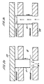
- valve 11 When the valve 11 is displaced by spring 40 from its position in Figure 2a into engagement with the valve seat 22 then fluid can flow from the fluid conduit 16 through the tubular passage in the sleeve 11 via the gallery 15 to the fluid conduit 14 which allows for return of the hydraulic fluid to a fluid reservoir.
- the fluid conduit 12 is sealed off by engagement of the tubular sleeve 11 with the valve seat 22.
- an O-ring 24 which surrounds the exterior surface of the sleeve 11 and prevents flow of hydraulic fluid from the fluid conduit 12 to the fluid conduit 14 through the annular gap between the sleeve 11 and the surrounding valve housing.
- the O-ring 24 deforms elastically on sliding of the sleeve 11 so that there is no sliding motion between the seal 24 and the sleeve 11.
- a plurality of ring seals 200, 201, 202 and 203 act between the external surface of the inner parts of the valve and the surrounding surface of the valve housing to prevent escape of fluid from the valve chamber and to prevent flow of fluid past the valve components from the pressure line 12 to the return line 14. It is possible that these could be replaced by a labyrinth seal arrangement.
- annular aperture 210 surrounding the washer 41. This allows communication between the cavity in which the spring 40 is located and the gallery 15 and therefore the return line 14. This prevents a build up of fluid pressure in the spring cavity which might inhibit the action of the spring 40.
- the illustrated valve is a digital switching valve, which will switch the fluid conduit 16 between communication with the pressure line attached to the valve and the return line attached to the valve.
- the valve will be bi-stable.
- the position of the sleeve 11 will not be precisely controlled in order to specify a gap of a chosen distance between the sleeve 11 and one of the end faces 22 and 23 in order to meter the flow of fluid through the valve.
- Metering of the flow of fluid through the valve will be achieved by supplying a pulse width modulated control signal to the valve so that the frequency of switching of the sleeve 11 between its two extreme positions will control the rate of flow of fluid through the valve.
- control line 16 is always isolated from the pressure line 12 unless the valve is powered, because of the action of the spring 40.
- This is generally a preferred failsafe arrangement.
- the valve will connect an actuator for an engine valve to the return line for a greater percentage of time than it connects the actuator to the pressure line.
- the "O" rings 33 and 24 mentioned above could be bonded respectively to the rod 17 and the sleeve 11 and/or to the facing surfaces of the valve housing.
- the "O" rings 33, 24 would then flex to allow the necessary movement. Indeed it is possible that the resilience of the seals 33, 24 could be used to provide a biassing force instead of the spring 40.
- the spring 40 illustrated above could be a single spring or a stack of springs.
Landscapes
- Engineering & Computer Science (AREA)
- General Engineering & Computer Science (AREA)
- Mechanical Engineering (AREA)
- Magnetically Actuated Valves (AREA)
- Fluid-Driven Valves (AREA)
- Fluid-Pressure Circuits (AREA)
- Multiple-Way Valves (AREA)
- Safety Valves (AREA)
Claims (8)
- Regelventilsystem zum Regeln des Durchsatzes von Hydraulikfluid, umfassend:ein Regelventil mit:einem Ventilgehäuse (10) und einer Hülse (11), die in einer Ventilkammer in dem Ventilgehäuse (10) verschiebbar ist;einer ersten Fluidleitung (12), welche die Ventilkammer mit einer Quelle von unter Druck stehendem Hydraulikfluid verbindet;einer zweiten Fluidleitung (14), welche die Ventilkammer mit einem Fluidrücklauf zum Rückführen von Hydraulikfluid zu einem Behälter verbindet; undeiner dritten Fluidleitung (16), welche die Ventilkammer verbindet, um einer Vorrichtung, die den durch das Regelventil geregelten Hydraulikfluiddurchsatz nutzt, Hydraulikfluid zuzuführen und von dieser zu empfangen, wobei:die Hülse (11) eine rohrförmige Hülse mit einem entlang ihrer gesamten Länge durch diese hindurch verlaufenden rohrförmigen Durchgang ist;das Ventilgehäuse ein Paar von voneinander beabstandeten Ventilsitzoberflächen (22, 23) aufweist, eine erste Ventilsitzoberfläche (22), mit der ein erstes Ende der rohrförmigen Hülse in Eingriff gelangen kann, und eine zweite Ventilsitzoberfläche (23), mit der ein zweites Ende der rohrförmigen Hülse in Eingriff gelangen kann;die dritte Fluidleitung (16) über eine Öffnung, die durch die erste Ventilsitzoberfläche (22) umgeben ist, in die Ventilkammer einmündet;wenn das erste Ende der rohrförmigen Hülse (11) mit der ersten Ventilsitzoberfläche (22) in Eingriff steht, Fluid axial die gesamte Länge des rohrförmigen Durchgangs in der Hülse (11) von der dritten Fluidleitung (16) und dann radial zu der zweiten Fluidleitung (14) hinaus strömt, und wenn das zweite Ende der rohrförmigen Hülse (11) mit der zweiten Ventilsitzoberfläche (23) in Eingriff steht, Fluid radial von der rohrförmigen Hülse (11) über das erste Ende davon durch einen Spalt zwischen dem ersten Ende der rohrförmigen Hülse (11) und dem ersten Ventilsitz (22) von der ersten Fluidleitung (12) zu der dritten Fluidleitung (16) strömt;ein Federmittel (40) die Hülse (11) in Eingriff mit der ersten Ventilsitzoberfläche (22) vorspannt; unddie rohrförmige Hülse (11) durch eine Stange (17) mit einem Anker (18) verbunden ist, der außerhalb der Ventilkammer angeordnet ist, wobei der Anker (18) innerhalb einer elektrischen Spule (19) angeordnet ist, die ebenfalls außerhalb der Ventilkammer angeordnet ist;dadurch gekennzeichnet, dass:das Federmittel (40) eine Feder (40) umfasst, die zwischen einem Federsitz (41), der in dem Ventilgehäuse vorgesehen ist, und einem Federsitz (42), der an dem Äußeren der Hülse befestigt ist, wirkt, so dass Kräfte, die auf die Stange (17) aufgebracht werden, nur Kräfte sind, welche die Stange (17) in Spannung versetzen und die Stange (17) nicht mit einem Biegemoment oder einer Kompressionskraft beaufschlagt wird.
- Regelventilsystem zum Regeln des Durchsatzes von Hydraulikfluid, umfassend:ein Regelventil mit:einem Ventilgehäuse (10); und einer Hülse (11), die in einer Ventilkammer in dem Ventilgehäuse (10) verschiebbar ist;einer ersten Fluidleitung (12), welche die Ventilkammer mit einer Quelle von unter Druck stehendem Hydraulikfluid verbindet;einer zweiten Fluidleitung (14), welche die Ventilkammer mit einem Fluidrücklauf zum Rückführen von Hydraulikfluid zu einem Behälter verbindet; undeiner dritten Fluidleitung (16), welche die Ventilkammer verbindet, um einer Vorrichtung, die den durch das Regelventil geregelten Hydraulikfluiddurchsatz nutzt, Hydraulikfluid zuzuführen und von dieser zu empfangen, wobei:die Hülse (11) eine rohrförmige Hülse mit einem entlang ihrer gesamten Länge durch diese hindurch verlaufenden rohrförmigen Durchgang ist;das Ventilgehäuse ein Paar von voneinander beabstandeten Ventilsitzoberflächen (22, 23) aufweist, eine erste Ventilsitzoberfläche (22), mit der ein erstes Ende der rohrförmigen Hülse in Eingriff gelangen kann, und eine zweite Ventilsitzoberfläche (23), mit der ein zweites Ende der rohrförmigen Hülse in Eingriff gelangen kann;die dritte Fluidleitung (16) über eine Öffnung, die durch die erste Ventilsitzoberfläche (22) umgeben ist, in die Ventilkammer einmündet;wenn das erste Ende des rohrförmigen Hülsenventils (11) mit der ersten Ventilsitzobexfläche (22) in Eingriff steht, Fluid axial entlang der gesamten Länge des rohrförmigen Durchgangs in der Hülse (11) und dann radial von der ersten Leitung (12) zu der dritten Fluidleitung (16) strömt, und wenn das zweite Ende der rohrförmigen Hülse (11) mit der zweiten Ventilsitzoberfläche (23) in Eingriff steht, Fluid radial von der rohrförmigen Hülse (11) über das erste Ende davon durch einen Spalt zwischen dem ersten Ende der rohrförmigen Hülse (11) und dem ersten Ventilsitz (22) von der dritten Fluidleitung (16) zu der zweiten Fluidleitung (14) strömt;ein Federmittel (40) die Hülse (11) in Eingriff mit der ersten Ventilsitzoberfläche (22) vorspannt; unddie rohrförmige Hülse (11) durch eine Stange (17) mit einem Anker (18) verbunden ist, der außerhalb der Ventilkammer angeordnet ist, wobei der Anker (18) innerhalb einer elektrischen Spule (19) angeordnet ist, die ebenfalls außerhalb der Ventilkammer angeordnet ist;dadurch gekennzeichnet, dass:das Federmittel (40) eine Feder (40) umfasst, die zwischen einem Federsitz (41), der in dem Ventilgehäuse vorgesehen ist, und einem Federsitz (42), der an dem Äußeren der Hülse befestigt ist, wirkt, so dass Kräfte, die auf die Stange (17) aufgebracht werden, nur Kräfte sind, welche die Stange (17) in Spannung versetzen und die Stange (17) nicht mit einem Biegemoment oder einer Kompressionskraft beaufschlagt wird.
- Regelventilsystem nach Anspruch 1 oder Anspruch 2, wobei die Feder (40) eine Vorspannung auf die Hülse (11) aufbringt, die durch eine magnetische Kraft, welche auf den Anker (18) durch ein Magnetfeld aufgebracht wird, das durch die elektrische Spule (19) erzeugt wird, überwunden werden muss, ehe sich die Hülse (11) von der ersten Ventilsitzoberfläche (22) wegbewegt.
- Regelventilsystem nach einem beliebigen der vorhergehenden Ansprüche, wobei eine verformbare Dichtung (24) vorgesehen ist, um zwischen dem Äußeren der rohrförmigen Hülse (11) und der gegenüberliegenden Fläche des Ventilgehäuses zu wirken, um zu verhindern, dass Fluid die Außenseite der rohrförmigen Hülse (11) entlang zwischen der ersten und der zweiten Fluidleitung (12, 14) hindurchtritt, und wobei sich die verformbare Dichtung (24) verformt, wenn die Hülse (11) in der Ventilkammer gleitet, um Gleitkontakt zwischen der Hülse und der verformbaren Dichtung zu reduzieren oder zu verhindern.
- Regelventilsystem nach einem beliebigen der vorhergehenden Ansprüche, wobei die erste Fluidleitung (12) über eine Galerie (13), die das erste Ende des rohrförmigen Hülsenventils umgibt, in die Ventilkammer einmündet.
- Regelventilsystem nach einem beliebigen der vorhergehenden Ansprüche, wobei die zweite Fluidleitung (14) über eine Galerie (15), die das zweite Ende des rohrförmigen Hülsenventils (11) umgibt, in die Ventilkammer einmündet.
- Regelventilsystem nach einem beliebigen der vorhergehenden Ansprüche, wobei das rohrförmige Hülsenventil (11) eine rohrförmige Wand aufweist, deren Dicke sich an beiden Enden des rohrförmigen Hülsenventils verjüngt.
- Regelventilsystem nach einem beliebigen der vorhergehenden Ansprüche, welches verwendet wird, um einen hydraulischen Stellantrieb zu steuern, wobei das Regelventil als digitales Ventil betrieben wird, mit einer Fluidströmungsgeschwindigkeit durch das Regelventil, die durch Steuern eines Schaltzeitpunkts der Hülse (11) zwischen Eingriff mit dem ersten und dem zweiten Ventilsitz (22, 23) variiert wird.
Applications Claiming Priority (3)
| Application Number | Priority Date | Filing Date | Title |
|---|---|---|---|
| GB0217641 | 2002-07-30 | ||
| GB0217641A GB2391287B (en) | 2002-07-30 | 2002-07-30 | Control valve for controlling flow of hydraulic fluid |
| PCT/GB2003/003209 WO2004011833A1 (en) | 2002-07-30 | 2003-07-30 | Control valve for controlling flow of hydraulic fluid |
Publications (2)
| Publication Number | Publication Date |
|---|---|
| EP1525416A1 EP1525416A1 (de) | 2005-04-27 |
| EP1525416B1 true EP1525416B1 (de) | 2008-12-17 |
Family
ID=9941376
Family Applications (1)
| Application Number | Title | Priority Date | Filing Date |
|---|---|---|---|
| EP03740850A Expired - Lifetime EP1525416B1 (de) | 2002-07-30 | 2003-07-30 | Steuerventil zur durchflussregelung von druckmittelströmen |
Country Status (9)
| Country | Link |
|---|---|
| US (1) | US7255132B2 (de) |
| EP (1) | EP1525416B1 (de) |
| JP (1) | JP4533746B2 (de) |
| CN (1) | CN100398886C (de) |
| AT (1) | ATE418036T1 (de) |
| AU (1) | AU2003281727A1 (de) |
| DE (1) | DE60325368D1 (de) |
| GB (1) | GB2391287B (de) |
| WO (1) | WO2004011833A1 (de) |
Families Citing this family (3)
| Publication number | Priority date | Publication date | Assignee | Title |
|---|---|---|---|---|
| US8127791B2 (en) * | 2005-12-21 | 2012-03-06 | Saturn Electronics & Engineering, Inc. | Solenoid operated fluid control valve |
| US8656941B1 (en) * | 2010-01-11 | 2014-02-25 | Jansen's Aircraft System Controls, Inc. | Flow control valve |
| JP6333086B2 (ja) * | 2014-06-26 | 2018-05-30 | 株式会社不二工機 | 三方電磁弁 |
Family Cites Families (28)
| Publication number | Priority date | Publication date | Assignee | Title |
|---|---|---|---|---|
| US1785289A (en) * | 1928-04-24 | 1930-12-16 | Tuker John Wilson | Balanced valve |
| US2705020A (en) * | 1950-10-26 | 1955-03-29 | Virgil L Frantz | Fluid pressure actuated control valve |
| US3548877A (en) * | 1969-05-19 | 1970-12-22 | Ite Imperial Corp | High speed three-way valve |
| US3768518A (en) * | 1971-03-01 | 1973-10-30 | V Roth | Fluid transfer valve |
| CH542386A (de) | 1971-05-06 | 1973-09-30 | Saurer Ag Adolph | Kombiniertes Misch- und Mengenregulierventil |
| US3848637A (en) * | 1973-05-07 | 1974-11-19 | Ite Imperial Corp | High speed four-way valve |
| JPS5936148B2 (ja) * | 1976-06-04 | 1984-09-01 | 三菱電機株式会社 | しや断器用制御弁 |
| JPS5719498Y2 (de) * | 1977-03-23 | 1982-04-23 | ||
| IT1091488B (it) * | 1977-11-21 | 1985-07-06 | Fiat Spa | Valvola idraulica universale a tre vie |
| GB2056627B (en) * | 1979-08-14 | 1983-03-23 | Crosweller & Co Ltd W | Mixing valve |
| GB2071279A (en) * | 1980-03-06 | 1981-09-16 | Reliance Hydrotech Ltd | Combined anti-dribble and dump valve |
| DE3125143A1 (de) * | 1981-06-26 | 1983-01-13 | Mannesmann Rexroth GmbH, 8770 Lohr | "druckminderventil" |
| US4887643A (en) * | 1982-03-01 | 1989-12-19 | Koomey, Inc. | Pilot actuated spool valve |
| DE3307554C2 (de) * | 1983-03-03 | 1985-09-26 | Mannesmann Rexroth GmbH, 8770 Lohr | Elektrisch regelbares Druckreduzierventil |
| US4565217A (en) * | 1983-06-30 | 1986-01-21 | Acumeter Laboratories, Inc. | Three-way poppet valve, method and apparatus |
| CN87203331U (zh) * | 1987-06-01 | 1988-03-02 | 苏恩远 | 截止-减压组合阀 |
| DE3814156A1 (de) * | 1988-04-27 | 1989-11-09 | Mesenich Gerhard | Pulsmoduliertes hydraulikventil |
| US4917150A (en) * | 1988-07-29 | 1990-04-17 | Colt Industries Inc. | Solenoid operated pressure control valve |
| JPH0344282U (de) * | 1989-09-11 | 1991-04-24 | ||
| US5064166A (en) | 1990-09-20 | 1991-11-12 | Ford Motor Company | Solenoid valve with high flow capacity and low energy consumption |
| US5246033A (en) * | 1991-11-15 | 1993-09-21 | Robert Bosch Gmbh | Electromagnetically actuatable double seat valve |
| US5211198A (en) * | 1992-10-15 | 1993-05-18 | Humphrey Products Company | Poppet construction for valve |
| CN2156328Y (zh) * | 1993-05-21 | 1994-02-16 | 华南理工大学 | 一种大流量高速开关阀 |
| JP3671411B2 (ja) * | 1996-10-21 | 2005-07-13 | 株式会社デンソー | 流体圧力制御用の三方電磁弁 |
| US5778932A (en) * | 1997-06-04 | 1998-07-14 | Vickers, Incorporated | Electrohydraulic proportional pressure reducing-relieving valve |
| EP1032375B1 (de) * | 1998-09-28 | 2005-07-13 | Tiefenbach Bergbautechnik GmbH | Hydraulisches wegeventil |
| DE10037793B4 (de) * | 2000-08-03 | 2007-05-24 | Hydraulik-Ring Gmbh | Magnetventil, insbesondere Druckregelventil |
| DE10121616A1 (de) * | 2001-05-03 | 2002-11-07 | Mueller Co Ax Gmbh | Koaxialventil |
-
2002
- 2002-07-30 GB GB0217641A patent/GB2391287B/en not_active Expired - Fee Related
-
2003
- 2003-07-30 EP EP03740850A patent/EP1525416B1/de not_active Expired - Lifetime
- 2003-07-30 US US10/522,323 patent/US7255132B2/en not_active Expired - Fee Related
- 2003-07-30 WO PCT/GB2003/003209 patent/WO2004011833A1/en not_active Ceased
- 2003-07-30 CN CNB038173476A patent/CN100398886C/zh not_active Expired - Fee Related
- 2003-07-30 DE DE60325368T patent/DE60325368D1/de not_active Expired - Lifetime
- 2003-07-30 AU AU2003281727A patent/AU2003281727A1/en not_active Abandoned
- 2003-07-30 JP JP2004523947A patent/JP4533746B2/ja not_active Expired - Fee Related
- 2003-07-30 AT AT03740850T patent/ATE418036T1/de not_active IP Right Cessation
Also Published As
| Publication number | Publication date |
|---|---|
| ATE418036T1 (de) | 2009-01-15 |
| GB2391287B (en) | 2004-11-03 |
| DE60325368D1 (de) | 2009-01-29 |
| EP1525416A1 (de) | 2005-04-27 |
| JP4533746B2 (ja) | 2010-09-01 |
| GB0217641D0 (en) | 2002-09-11 |
| US20050257842A1 (en) | 2005-11-24 |
| CN1671984A (zh) | 2005-09-21 |
| WO2004011833A1 (en) | 2004-02-05 |
| US7255132B2 (en) | 2007-08-14 |
| JP2005534872A (ja) | 2005-11-17 |
| GB2391287A (en) | 2004-02-04 |
| AU2003281727A1 (en) | 2004-02-16 |
| CN100398886C (zh) | 2008-07-02 |
Similar Documents
| Publication | Publication Date | Title |
|---|---|---|
| US7159615B2 (en) | Flow control valve | |
| US6161722A (en) | Liquid dispensing device and methods utilizing a magnetically coupled valve stem | |
| JP5592641B2 (ja) | 電気油圧ポペットパイロット弁によって操作されるポペット弁 | |
| EP1643174B1 (de) | Pneumatisches Ventil | |
| US5718264A (en) | High speed 3-way control valve | |
| JP2010114254A (ja) | ソレノイド | |
| EP1941124B1 (de) | Anwendungen von leistungsarmen bistabilen stellgliedern im bohrloch | |
| GB2332538A (en) | Integrated electrohydraulic actuator | |
| JP2004069069A (ja) | ソレノイド作動圧力制御弁 | |
| EP2334962A1 (de) | Ventil zur abgabe von fluiden | |
| JPWO2018180367A1 (ja) | 電磁比例弁 | |
| US7255132B2 (en) | Control valve for controlling flow of hydraulic fluid | |
| JPH10318421A (ja) | 比例圧力制御弁 | |
| JP6592300B2 (ja) | バイパス通路付きチェック弁を備えるソレノイドバルブ | |
| JPWO2009005149A1 (ja) | ソレノイドバルブ | |
| NZ231432A (en) | Disc type electromagnetic valve with diaphragm connected to armature directly or indirectly | |
| JP4218510B2 (ja) | リニヤアクチュエータ | |
| US5836230A (en) | High speed 2-way control valve | |
| CN114901528A (zh) | 电磁阀 | |
| EP0400152A1 (de) | Regelungsventilanordnung für flussrate und struktur zur reduzierung der fliesskräfte | |
| EP2807413B1 (de) | Kraftmultiplizierendes magnetventil | |
| JP2003156170A (ja) | 二段式水圧用電磁弁 | |
| JPH01275969A (ja) | 流量制御弁 | |
| RU2164633C1 (ru) | Пневмораспределитель | |
| US5546988A (en) | Servo multiplexing system |
Legal Events
| Date | Code | Title | Description |
|---|---|---|---|
| PUAI | Public reference made under article 153(3) epc to a published international application that has entered the european phase |
Free format text: ORIGINAL CODE: 0009012 |
|
| 17P | Request for examination filed |
Effective date: 20041214 |
|
| AK | Designated contracting states |
Kind code of ref document: A1 Designated state(s): AT BE BG CH CY CZ DE DK EE ES FI FR GB GR HU IE IT LI LU MC NL PT RO SE SI SK TR |
|
| AX | Request for extension of the european patent |
Extension state: AL LT LV MK |
|
| 17Q | First examination report despatched |
Effective date: 20050512 |
|
| DAX | Request for extension of the european patent (deleted) | ||
| 17Q | First examination report despatched |
Effective date: 20050512 |
|
| GRAP | Despatch of communication of intention to grant a patent |
Free format text: ORIGINAL CODE: EPIDOSNIGR1 |
|
| GRAS | Grant fee paid |
Free format text: ORIGINAL CODE: EPIDOSNIGR3 |
|
| GRAA | (expected) grant |
Free format text: ORIGINAL CODE: 0009210 |
|
| AK | Designated contracting states |
Kind code of ref document: B1 Designated state(s): AT BE BG CH CY CZ DE DK EE ES FI FR GB GR HU IE IT LI LU MC NL PT RO SE SI SK TR |
|
| REG | Reference to a national code |
Ref country code: GB Ref legal event code: FG4D |
|
| REG | Reference to a national code |
Ref country code: CH Ref legal event code: EP |
|
| REG | Reference to a national code |
Ref country code: IE Ref legal event code: FG4D |
|
| REF | Corresponds to: |
Ref document number: 60325368 Country of ref document: DE Date of ref document: 20090129 Kind code of ref document: P |
|
| PG25 | Lapsed in a contracting state [announced via postgrant information from national office to epo] |
Ref country code: NL Free format text: LAPSE BECAUSE OF FAILURE TO SUBMIT A TRANSLATION OF THE DESCRIPTION OR TO PAY THE FEE WITHIN THE PRESCRIBED TIME-LIMIT Effective date: 20081217 Ref country code: SI Free format text: LAPSE BECAUSE OF FAILURE TO SUBMIT A TRANSLATION OF THE DESCRIPTION OR TO PAY THE FEE WITHIN THE PRESCRIBED TIME-LIMIT Effective date: 20081217 Ref country code: FI Free format text: LAPSE BECAUSE OF FAILURE TO SUBMIT A TRANSLATION OF THE DESCRIPTION OR TO PAY THE FEE WITHIN THE PRESCRIBED TIME-LIMIT Effective date: 20081217 |
|
| NLV1 | Nl: lapsed or annulled due to failure to fulfill the requirements of art. 29p and 29m of the patents act | ||
| PG25 | Lapsed in a contracting state [announced via postgrant information from national office to epo] |
Ref country code: ES Free format text: LAPSE BECAUSE OF FAILURE TO SUBMIT A TRANSLATION OF THE DESCRIPTION OR TO PAY THE FEE WITHIN THE PRESCRIBED TIME-LIMIT Effective date: 20090328 Ref country code: BG Free format text: LAPSE BECAUSE OF FAILURE TO SUBMIT A TRANSLATION OF THE DESCRIPTION OR TO PAY THE FEE WITHIN THE PRESCRIBED TIME-LIMIT Effective date: 20090317 Ref country code: BE Free format text: LAPSE BECAUSE OF FAILURE TO SUBMIT A TRANSLATION OF THE DESCRIPTION OR TO PAY THE FEE WITHIN THE PRESCRIBED TIME-LIMIT Effective date: 20081217 Ref country code: EE Free format text: LAPSE BECAUSE OF FAILURE TO SUBMIT A TRANSLATION OF THE DESCRIPTION OR TO PAY THE FEE WITHIN THE PRESCRIBED TIME-LIMIT Effective date: 20081217 Ref country code: RO Free format text: LAPSE BECAUSE OF FAILURE TO SUBMIT A TRANSLATION OF THE DESCRIPTION OR TO PAY THE FEE WITHIN THE PRESCRIBED TIME-LIMIT Effective date: 20081217 |
|
| PG25 | Lapsed in a contracting state [announced via postgrant information from national office to epo] |
Ref country code: CZ Free format text: LAPSE BECAUSE OF FAILURE TO SUBMIT A TRANSLATION OF THE DESCRIPTION OR TO PAY THE FEE WITHIN THE PRESCRIBED TIME-LIMIT Effective date: 20081217 Ref country code: AT Free format text: LAPSE BECAUSE OF FAILURE TO SUBMIT A TRANSLATION OF THE DESCRIPTION OR TO PAY THE FEE WITHIN THE PRESCRIBED TIME-LIMIT Effective date: 20081217 Ref country code: SE Free format text: LAPSE BECAUSE OF FAILURE TO SUBMIT A TRANSLATION OF THE DESCRIPTION OR TO PAY THE FEE WITHIN THE PRESCRIBED TIME-LIMIT Effective date: 20090317 Ref country code: PT Free format text: LAPSE BECAUSE OF FAILURE TO SUBMIT A TRANSLATION OF THE DESCRIPTION OR TO PAY THE FEE WITHIN THE PRESCRIBED TIME-LIMIT Effective date: 20090518 |
|
| PG25 | Lapsed in a contracting state [announced via postgrant information from national office to epo] |
Ref country code: SK Free format text: LAPSE BECAUSE OF FAILURE TO SUBMIT A TRANSLATION OF THE DESCRIPTION OR TO PAY THE FEE WITHIN THE PRESCRIBED TIME-LIMIT Effective date: 20081217 |
|
| PLBE | No opposition filed within time limit |
Free format text: ORIGINAL CODE: 0009261 |
|
| STAA | Information on the status of an ep patent application or granted ep patent |
Free format text: STATUS: NO OPPOSITION FILED WITHIN TIME LIMIT |
|
| PG25 | Lapsed in a contracting state [announced via postgrant information from national office to epo] |
Ref country code: DK Free format text: LAPSE BECAUSE OF FAILURE TO SUBMIT A TRANSLATION OF THE DESCRIPTION OR TO PAY THE FEE WITHIN THE PRESCRIBED TIME-LIMIT Effective date: 20081217 |
|
| 26N | No opposition filed |
Effective date: 20090918 |
|
| PG25 | Lapsed in a contracting state [announced via postgrant information from national office to epo] |
Ref country code: MC Free format text: LAPSE BECAUSE OF NON-PAYMENT OF DUE FEES Effective date: 20090731 |
|
| REG | Reference to a national code |
Ref country code: CH Ref legal event code: PL |
|
| REG | Reference to a national code |
Ref country code: IE Ref legal event code: MM4A |
|
| PG25 | Lapsed in a contracting state [announced via postgrant information from national office to epo] |
Ref country code: CH Free format text: LAPSE BECAUSE OF NON-PAYMENT OF DUE FEES Effective date: 20090731 Ref country code: LI Free format text: LAPSE BECAUSE OF NON-PAYMENT OF DUE FEES Effective date: 20090731 |
|
| PG25 | Lapsed in a contracting state [announced via postgrant information from national office to epo] |
Ref country code: IE Free format text: LAPSE BECAUSE OF NON-PAYMENT OF DUE FEES Effective date: 20090730 |
|
| PG25 | Lapsed in a contracting state [announced via postgrant information from national office to epo] |
Ref country code: GR Free format text: LAPSE BECAUSE OF FAILURE TO SUBMIT A TRANSLATION OF THE DESCRIPTION OR TO PAY THE FEE WITHIN THE PRESCRIBED TIME-LIMIT Effective date: 20090318 |
|
| PG25 | Lapsed in a contracting state [announced via postgrant information from national office to epo] |
Ref country code: IT Free format text: LAPSE BECAUSE OF FAILURE TO SUBMIT A TRANSLATION OF THE DESCRIPTION OR TO PAY THE FEE WITHIN THE PRESCRIBED TIME-LIMIT Effective date: 20081217 |
|
| PG25 | Lapsed in a contracting state [announced via postgrant information from national office to epo] |
Ref country code: LU Free format text: LAPSE BECAUSE OF NON-PAYMENT OF DUE FEES Effective date: 20090730 |
|
| PG25 | Lapsed in a contracting state [announced via postgrant information from national office to epo] |
Ref country code: HU Free format text: LAPSE BECAUSE OF FAILURE TO SUBMIT A TRANSLATION OF THE DESCRIPTION OR TO PAY THE FEE WITHIN THE PRESCRIBED TIME-LIMIT Effective date: 20090618 |
|
| PG25 | Lapsed in a contracting state [announced via postgrant information from national office to epo] |
Ref country code: TR Free format text: LAPSE BECAUSE OF FAILURE TO SUBMIT A TRANSLATION OF THE DESCRIPTION OR TO PAY THE FEE WITHIN THE PRESCRIBED TIME-LIMIT Effective date: 20081217 |
|
| PG25 | Lapsed in a contracting state [announced via postgrant information from national office to epo] |
Ref country code: CY Free format text: LAPSE BECAUSE OF FAILURE TO SUBMIT A TRANSLATION OF THE DESCRIPTION OR TO PAY THE FEE WITHIN THE PRESCRIBED TIME-LIMIT Effective date: 20081217 |
|
| PGFP | Annual fee paid to national office [announced via postgrant information from national office to epo] |
Ref country code: DE Payment date: 20140724 Year of fee payment: 12 |
|
| PGFP | Annual fee paid to national office [announced via postgrant information from national office to epo] |
Ref country code: GB Payment date: 20140725 Year of fee payment: 12 Ref country code: FR Payment date: 20140731 Year of fee payment: 12 |
|
| REG | Reference to a national code |
Ref country code: DE Ref legal event code: R119 Ref document number: 60325368 Country of ref document: DE |
|
| GBPC | Gb: european patent ceased through non-payment of renewal fee |
Effective date: 20150730 |
|
| PG25 | Lapsed in a contracting state [announced via postgrant information from national office to epo] |
Ref country code: GB Free format text: LAPSE BECAUSE OF NON-PAYMENT OF DUE FEES Effective date: 20150730 Ref country code: DE Free format text: LAPSE BECAUSE OF NON-PAYMENT OF DUE FEES Effective date: 20160202 |
|
| REG | Reference to a national code |
Ref country code: FR Ref legal event code: ST Effective date: 20160331 |
|
| PG25 | Lapsed in a contracting state [announced via postgrant information from national office to epo] |
Ref country code: FR Free format text: LAPSE BECAUSE OF NON-PAYMENT OF DUE FEES Effective date: 20150731 |