EP1525396B2 - Wind turbine comprising a closed cooling circuit - Google Patents
Wind turbine comprising a closed cooling circuit Download PDFInfo
- Publication number
- EP1525396B2 EP1525396B2 EP03787656.2A EP03787656A EP1525396B2 EP 1525396 B2 EP1525396 B2 EP 1525396B2 EP 03787656 A EP03787656 A EP 03787656A EP 1525396 B2 EP1525396 B2 EP 1525396B2
- Authority
- EP
- European Patent Office
- Prior art keywords
- air
- nacelle
- tube bundle
- generator
- cooling circuit
- Prior art date
- Legal status (The legal status is an assumption and is not a legal conclusion. Google has not performed a legal analysis and makes no representation as to the accuracy of the status listed.)
- Expired - Lifetime
Links
Images
Classifications
-
- H—ELECTRICITY
- H02—GENERATION; CONVERSION OR DISTRIBUTION OF ELECTRIC POWER
- H02K—DYNAMO-ELECTRIC MACHINES
- H02K7/00—Arrangements for handling mechanical energy structurally associated with dynamo-electric machines, e.g. structural association with mechanical driving motors or auxiliary dynamo-electric machines
- H02K7/18—Structural association of electric generators with mechanical driving motors, e.g. with turbines
- H02K7/1807—Rotary generators
- H02K7/1823—Rotary generators structurally associated with turbines or similar engines
-
- F—MECHANICAL ENGINEERING; LIGHTING; HEATING; WEAPONS; BLASTING
- F03—MACHINES OR ENGINES FOR LIQUIDS; WIND, SPRING, OR WEIGHT MOTORS; PRODUCING MECHANICAL POWER OR A REACTIVE PROPULSIVE THRUST, NOT OTHERWISE PROVIDED FOR
- F03D—WIND MOTORS
- F03D80/00—Details, components or accessories not provided for in groups F03D1/00 - F03D17/00
- F03D80/40—Ice detection; De-icing means
-
- F—MECHANICAL ENGINEERING; LIGHTING; HEATING; WEAPONS; BLASTING
- F03—MACHINES OR ENGINES FOR LIQUIDS; WIND, SPRING, OR WEIGHT MOTORS; PRODUCING MECHANICAL POWER OR A REACTIVE PROPULSIVE THRUST, NOT OTHERWISE PROVIDED FOR
- F03D—WIND MOTORS
- F03D80/00—Details, components or accessories not provided for in groups F03D1/00 - F03D17/00
- F03D80/60—Cooling or heating of wind motors
-
- F—MECHANICAL ENGINEERING; LIGHTING; HEATING; WEAPONS; BLASTING
- F03—MACHINES OR ENGINES FOR LIQUIDS; WIND, SPRING, OR WEIGHT MOTORS; PRODUCING MECHANICAL POWER OR A REACTIVE PROPULSIVE THRUST, NOT OTHERWISE PROVIDED FOR
- F03D—WIND MOTORS
- F03D9/00—Adaptations of wind motors for special use; Combinations of wind motors with apparatus driven thereby; Wind motors specially adapted for installation in particular locations
- F03D9/20—Wind motors characterised by the driven apparatus
- F03D9/25—Wind motors characterised by the driven apparatus the apparatus being an electrical generator
-
- H—ELECTRICITY
- H02—GENERATION; CONVERSION OR DISTRIBUTION OF ELECTRIC POWER
- H02K—DYNAMO-ELECTRIC MACHINES
- H02K9/00—Arrangements for cooling or ventilating
- H02K9/10—Arrangements for cooling or ventilating by gaseous cooling medium flowing in closed circuit, a part of which is external to the machine casing
- H02K9/12—Arrangements for cooling or ventilating by gaseous cooling medium flowing in closed circuit, a part of which is external to the machine casing wherein the cooling medium circulates freely within the casing
-
- H—ELECTRICITY
- H02—GENERATION; CONVERSION OR DISTRIBUTION OF ELECTRIC POWER
- H02K—DYNAMO-ELECTRIC MACHINES
- H02K7/00—Arrangements for handling mechanical energy structurally associated with dynamo-electric machines, e.g. structural association with mechanical driving motors or auxiliary dynamo-electric machines
- H02K7/18—Structural association of electric generators with mechanical driving motors, e.g. with turbines
- H02K7/1807—Rotary generators
- H02K7/1823—Rotary generators structurally associated with turbines or similar engines
- H02K7/183—Rotary generators structurally associated with turbines or similar engines wherein the turbine is a wind turbine
- H02K7/1838—Generators mounted in a nacelle or similar structure of a horizontal axis wind turbine
-
- Y—GENERAL TAGGING OF NEW TECHNOLOGICAL DEVELOPMENTS; GENERAL TAGGING OF CROSS-SECTIONAL TECHNOLOGIES SPANNING OVER SEVERAL SECTIONS OF THE IPC; TECHNICAL SUBJECTS COVERED BY FORMER USPC CROSS-REFERENCE ART COLLECTIONS [XRACs] AND DIGESTS
- Y02—TECHNOLOGIES OR APPLICATIONS FOR MITIGATION OR ADAPTATION AGAINST CLIMATE CHANGE
- Y02E—REDUCTION OF GREENHOUSE GAS [GHG] EMISSIONS, RELATED TO ENERGY GENERATION, TRANSMISSION OR DISTRIBUTION
- Y02E10/00—Energy generation through renewable energy sources
- Y02E10/70—Wind energy
- Y02E10/72—Wind turbines with rotation axis in wind direction
Definitions
- the invention relates to a wind turbine with a generator arranged in a nacelle, a turbine with at least one rotor blade, wherein the generator has a cooling circuit.
- the losses amount to approx. 5 to 7% of the installed rated output.
- a wind turbine is known in which in particular the generator is cooled by an air flow, which is generated by a resulting at an orifice of a rotor blade vacuum. Due to this negative pressure There is a pressure gradient between each mouth of a rotor blade and an opening on the side facing away from the rotor blade of the nacelle. As a result, ambient air is sucked in against the actual wind direction at the opening, which flows via the flow path through the nacelle and through the interior of a rotor blade to the mouth of this rotor blade.
- the disadvantage here is that it is a draft ventilation, which includes the disadvantages of saline air, especially in off-shore installation. In addition, arise through the mouths on the rotor blades noise problems.
- a wind turbine is known with a arranged in a nacelle generator turbine with at least one rotor blade wherein at least the generator has a closed primary circuit, and wherein the nacelle has means that allow cooling of the primary circuit.
- the invention is therefore an object of the invention to provide a wind turbine, which is equipped with a reliable cooling, so that in particular both off-shore operation both maintenance operations and failures are avoided by polluted or salty cooling air.
- the cooling by the primary circuit is not limited to the generator, but advantageously includes other electrical equipment or inverter, slip ring body of the generator with a.
- the site of this wind turbine is independent of unfavorable external conditions. That Even in the off-shore area with moist salty air due to an internal encapsulated primary cooling circuit system sufficient cooling is ensured by the wind on the nacelle.
- the air velocities occurring at the nacelle are dependent on wind strength, whereby due to the system there is a proportional relationship between wind strength and generator power or generator losses.
- the nacelle is designed as a secondary air cooler, so that there is an air-air cooler.
- the secondary air cooler is designed as a tube bundle, which allows a heat exchange attached to the nacelle or part of the nacelle.
- the tube bundle is mounted in the upper half of the nacelle.
- the heated air from the generator or other electrical equipment that is connected to the primary cooling circuit rises or is introduced by fans in the existing between the tube bundles spaces and cooled there by the sweeping through the tube bundle wind.
- the cooled air of the primary circuit is supplied to the generator or other electrical equipment located in the nacelle for cooling again.
- the tube bundle forms the heat exchanger between the primary and secondary circuits.
- the tubes have bruisenyergrDeutsch spallnde structures.
- a major advantage of this all versions compared to a machine with air-water coolers is the independent largely maintenance-free and reliable system that manages without additional reprocessing coolant at high altitude. There are only low maintenance and no equipment costs.
- the inventive design of a wind turbine is relatively compact and low maintenance. For this reason, fewer failures due to humid or salty air are to be expected compared to wind turbines with draft ventilation, in particular of the generators.
- the nacelle, rotor blades, especially in the cold season can also be heated. As a result, condensation on electrical equipment and ice formation on the rotor blades is avoided.
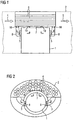
- FIG. 1 shows a heat source 1, which is arranged in a nacelle 2.
- the nacelle 2 is located on a tower, not shown, of a wind turbine.
- the heat source 1 may in particular be a generator or other electrical equipment not shown in detail, such as converters, slip ring space of the generator.
- the laminated core of the stator and / or the rotor is traversed in a conventional manner radially and / or axially with ventilation ducts. Furthermore, the air of the primary cooling circuit can flow through the air gap of the generator.
- This system is advantageously located on the top of the nacelle 2.
- the tube bundles 6 are flowed through in the axial direction of the on the nacelle 2, the rotor blades driving wind.
- the wind enters the system at the inlet 4 of the tube bundle 6 and exits heatedly at the outlet 5 of the tube bundle 6.
- the thermal transfer of the heat exchange of the existing in the air of the primary cooling circuit heat of the heat source 1 takes place at the stroking through the system of the tube bundle 6 wind.
- the heated air from the heat source 1 via an output 7 in the system of the tube bundle 6, is cooled there and cooled by convection and / or fan 8 of the heat source 1 is fed again.
- the transitions 10 denote the transitions between the primary cooling circuit and the tube bundle 6 designed as a heat exchanger.
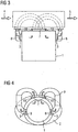
- FIG. 2 shows the arrangement of the tube bundle 6 in the nacelle 2.
- the respective tubes of the tube bundle 6 are cylindrical. They are advantageously provided with surface-enlarged structures in order to increase the cooling efficiency. Furthermore, it is made possible by the rotational movement of the nacelle 2 that the tube bundle 6 are aligned axially parallel to the wind direction due to the orientation of the rotor blades of the wind turbine, not shown. Thus, the air flow through the tube bundle 6 is increased, thus increasing the cooling efficiency.
- FIG. 3 shows in a further embodiment, a heat source 1 whose output 7 lead as a handle-shaped, tubular portion 9 outside the nacelle and are returned to the heat source 1 via the input 3.
- the heat transport of this primary cooling circuit is also done by natural convection and / or fan 8.
- the tubular sections 9 can also be assembled from individual parts on site.
- FIG. 4 shows in cross-section the basic arrangement of the pipe system of the primary cooling circuit of the heat source 1 whose tubes are in the wind, and are preferably executed with not shown surface enlarging structures.
- the convection of the heated air in the primary cooling circuit is facilitated by the fact that in the upper part of the nacelle, the output 7 and the middle part or lower part of the nacelle, the input 3 of the tubes are arranged.
- the inventive design of the wind turbine results over the previous cooling systems of a wind turbine the following advantages: There is no water intermediate circuit including the generator air-water cooler necessary. With a lying outside the heat source 1 Air-air cooler space is created in the cramped gondola 2. The reliability is significantly increased compared to conventional systems and the maintenance costs are reduced at the same time. There is no cooling water supply and no cooling water treatment and monitoring necessary. The energy consumption of secondary equipment such as water pump, monitoring equipment is reduced. Due to the heated air of the primary cooling circuit, the nacelle 2 is also heated. Likewise, the rotor blades can be heated by the heated air of the primary cooling circuit, so that icing problems are avoided, especially in winter. In this case, fans are advantageously required to provide the required circulating air movement.
Landscapes
- Engineering & Computer Science (AREA)
- Mechanical Engineering (AREA)
- Sustainable Development (AREA)
- Sustainable Energy (AREA)
- Chemical & Material Sciences (AREA)
- Combustion & Propulsion (AREA)
- Life Sciences & Earth Sciences (AREA)
- General Engineering & Computer Science (AREA)
- Power Engineering (AREA)
- Physics & Mathematics (AREA)
- Thermal Sciences (AREA)
- Wind Motors (AREA)
- Motor Or Generator Cooling System (AREA)
Description
Die Erfindung betrifft eine Windkraftanlage mit einem in einer Gondel angeordneten Generator, einer Turbine mit zumindest einem Rotorblatt, wobei der Generator einen Kühlkreislauf aufweist.The invention relates to a wind turbine with a generator arranged in a nacelle, a turbine with at least one rotor blade, wherein the generator has a cooling circuit.
Bei Umformung von Energie entstehen naturgemäß Verluste in Form von Wärme. Diese Verlustwärme tritt sowohl bei der Umformung der kinetischen Energie des Windes in elektrischen Energie im Generator einer Windkraftanlage auf, als auch bei der elektrischen Einspeisung der von der Windkraftanlage erzeugten Energie in ein elektrisches Versorgungsnetz. Diese Verlustwärme tritt bei den anderen elektrischen Betriebsmitteln, insbesondere der Leistungselektronik wie z.B. Wechselrichter oder Transformatoren auf. Ebenso tritt Wärme bei anderen Komponenten einer Windkraftanlage auf wie z.B. Getriebe, Lagern oder Steuereinheiten wie z.B. Hydraulikanlagen oder vergleichbaren Steuer- und Regelungseinrichtungen, mittels denen die Rotorblätter angestellt oder die Windkraftanläge zum Wind gestellt wird.When energy is transformed, naturally losses occur in the form of heat. This heat loss occurs both in the conversion of the kinetic energy of the wind into electrical energy in the generator of a wind turbine, as well as in the electrical feed of the energy generated by the wind turbine into an electrical supply network. This heat loss occurs in the other electrical equipment, in particular the power electronics such. Inverters or transformers. Likewise, heat occurs in other components of a wind turbine, such as e.g. Transmissions, bearings or control units such as e.g. Hydraulic systems or similar control and regulating devices, by means of which the rotor blades are turned on or the Windkraftanläge is turned to the wind.
Die Verluste betragen dabei ca. 5 bis 7% der installierten Nennleistung.The losses amount to approx. 5 to 7% of the installed rated output.
Diese Wärmeverluste werden bislang über Lüfter an die Umgebung abgeführt. Dabei wird mittels der Lüfter kalte Luft von außen angesaugt und das entsprechende Bauteil, z.B. der Generator gekühlt. Die erwärmte Luft wird anschließend wieder nach außen abgeführt. Dies ist insbesondere nachteilig, wenn die Außenluft feucht oder insbesondere in Küstenregionen salzhaltig ist und die zu kühlenden Elemente mit dieser feuchten und salzhaltigen Luft beaufschlagt werden.These heat losses have so far been dissipated via fans to the environment. In this case, by means of the fan cold air is sucked from the outside and the corresponding component, e.g. the generator cooled. The heated air is then discharged back to the outside. This is particularly disadvantageous if the outside air is moist or salty, especially in coastal regions, and the elements to be cooled are exposed to this moist and salty air.
Aus der
Aus der
Aus der
Aus der
Aus der
Der Erfindung liegt demnach die Aufgabe zugrunde eine Windkraftanlage zu schaffen, die mit einer zuverlässigen Kühlung ausgestattet ist, so dass insbesondere auch im Off-shore-Betrieb sowohl Wartungseinsätze als auch Ausfälle durch verschmutzte oder salzhaltige Kühlluft vermieden werden.The invention is therefore an object of the invention to provide a wind turbine, which is equipped with a reliable cooling, so that in particular both off-shore operation both maintenance operations and failures are avoided by polluted or salty cooling air.
Die Lösung der gestellten Aufgabe gelingt durch die Merkmale des Anspruchs 1.The solution of the problem is achieved by the features of
Die Kühlung durch den Primärkreislauf ist nicht nur auf den Generator begrenzt, sondern schließt vorteilhafterweise auch andere elektrische Betriebsmittel bzw. Umrichter, Schleifringkörper des Generator mit ein.The cooling by the primary circuit is not limited to the generator, but advantageously includes other electrical equipment or inverter, slip ring body of the generator with a.
Durch die erfindungsgemäße Trennung von Primär- und Sekundärkühlkreislauf ist der Aufstellungsort dieser Windkraftanlage unabhängig von ungünstigen äußeren Bedingungen. D.h. auch im Off-shore-Bereich bei feuchter salzhaltiger Luft ist aufgrund eines internen gekapselten Primär-Kühlkreislaufsystems eine ausreichende Kühlung durch den Wind an der Gondel gewährleistet. Die an der Gondel auftretenden Luftgeschwindigkeiten sind windstärkeabhängig, wobei systembedingt ein proportionaler Zusammenhang zwischen Windstärke und Generatorleistung bzw. Generatorverlusten besteht.Due to the separation of primary and secondary cooling circuit according to the invention, the site of this wind turbine is independent of unfavorable external conditions. That Even in the off-shore area with moist salty air due to an internal encapsulated primary cooling circuit system sufficient cooling is ensured by the wind on the nacelle. The air velocities occurring at the nacelle are dependent on wind strength, whereby due to the system there is a proportional relationship between wind strength and generator power or generator losses.
Vorteilhafterweise ist die Gondel dabei als sekundärer Luftkühler ausgeführt, so dass sich ein Luft-Luftkühler ergibt.Advantageously, the nacelle is designed as a secondary air cooler, so that there is an air-air cooler.
In einer bevorzugten Ausführung ist der sekundäre Luftkühler als Rohrbündel ausgeführt, der einen Wärmeaustausch gestattet das an der Gondel angebracht oder Teil der Gondel ist. Vorteilhafterweise ist dabei das Rohrbündel in der oberen Hälfte um die Gondel angebracht. Die erwärmte Luft vom Generator oder anderen elektrischen Betriebsmitteln, die an den Primär-Kühlkreislauf angeschlossen sind steigt auf oder wird durch Lüfter in die zwischen den Rohrbündel vorhandenen Zwischenräume eingeleitet und dort durch den durch das Rohrbündel streichenden Wind gekühlt. Durch natürliche Konvektion oder durch einen weiteren Lüfter wird die gekühlte Luft des Primär-Kreislaufs dem Generator oder weiteren in der Gondel befindlichen elektrischen Betriebsmitteln zur Kühlung erneut zugeführt. Dadurch, dass das Rohrbündel sich an der Gondel befinden, ist gewährleistet, dass die Rohre des Bündels mit ihrer Achse immer parallel zur Windrichtung ausgerichtet sind, so dass eine ausreichende Kühlwirkung durch die vorhandenen Windgeschwindigkeiten und damit den vorhandenen Luftdurchsatz des Rohrbündels gewährleistet ist. Das Rohrbündel bildet den Wärmetauscher zwischen dem Primär- und Sekundär-Kreislauf.In a preferred embodiment, the secondary air cooler is designed as a tube bundle, which allows a heat exchange attached to the nacelle or part of the nacelle. Advantageously, the tube bundle is mounted in the upper half of the nacelle. The heated air from the generator or other electrical equipment that is connected to the primary cooling circuit rises or is introduced by fans in the existing between the tube bundles spaces and cooled there by the sweeping through the tube bundle wind. By natural convection or by another fan, the cooled air of the primary circuit is supplied to the generator or other electrical equipment located in the nacelle for cooling again. The fact that the tube bundle are located on the nacelle, it is ensured that the tubes of the bundle are always aligned with its axis parallel to the wind direction, so that a sufficient cooling effect is ensured by the existing wind speeds and thus the existing air flow rate of the tube bundle. The tube bundle forms the heat exchanger between the primary and secondary circuits.
Um den Wärmeübergang besonders effizient zu gestalten, weisen die Rohre oberflächenyergrößernde Strukturen auf.In order to make the heat transfer particularly efficient, the tubes have Oberflächenyergrößgrößernde structures.
Ein großer Vorteil dieser sämtlichen Ausführungen gegenüber einer Maschine mit Luft-Wasser-Kühlern besteht in dem unabhängigen weitgehend wartungsfreien und betriebssicheren System, welches ohne zusätzliches aufzubereitendes Kühlmittel in großer Höhe auskommt. Es fallen lediglich geringe Wartungs- und keine Betriebsmittelkosten an. Die erfindungsgemäße Ausführung einer Windkraftanlage ist vergleichsweise kompakt und wartungsarm. Deshalb sind auch gegenüber Windkraftanlagen mit Durchzugsbelüftung insbesondere der Generatoren weniger Ausfälle durch feuchte oder salzhaltige Luft zu erwarten.A major advantage of this all versions compared to a machine with air-water coolers is the independent largely maintenance-free and reliable system that manages without additional reprocessing coolant at high altitude. There are only low maintenance and no equipment costs. The inventive design of a wind turbine is relatively compact and low maintenance. For this reason, fewer failures due to humid or salty air are to be expected compared to wind turbines with draft ventilation, in particular of the generators.
Durch die erwärmte Abluft des Primär-Kühlkreislaufs kann die Gondel, Rotorblätter, insbesondere in der kalten Jahreszeit auch beheizt werden. Dadurch wird Kondensatbildung an elektrischen Betriebsmitteln und Eisbildung an den Rotorblättern vermieden.Due to the heated exhaust air of the primary cooling circuit, the nacelle, rotor blades, especially in the cold season can also be heated. As a result, condensation on electrical equipment and ice formation on the rotor blades is avoided.
Die Erfindung sowie weitere vorteilhafte Ausgestaltungen der Erfindung gemäß Merkmale der Unteransprüche werden im folgenden anhand schematisch dargestellter Ausführungsbeispiele in der Zeichnung näher erläutert. Dabei zeigen:
- FIG 1 und 3
- Längsschnitte der erfindungsgemäßen Windkraftanlage,
- FIG 2 und 4
- Querschnitte der erfindungsgemäßen Windkraftanlage.
- FIGS. 1 and 3
- Longitudinal sections of the wind turbine according to the invention,
- FIGS. 2 and 4
- Cross sections of the wind turbine according to the invention.
Oberhalb der Wärmequelle 1 befindet sich in der Gondel 2 ein System von Rohrbündeln 6. Dieses System befindet sich vorteilhafterweise auf der Oberseite der Gondel 2. Die Rohrbündel 6 werden in axialer Richtung von dem an der Gondel 2, die Rotorblätter antreibenden Wind durchströmt. Der Wind tritt dabei am Einlass 4 der Rohrbündel 6 in das System ein und tritt erwärmt am Auslass 5 der Rohrbündel 6 aus. Zwischen Einlass 4 und Auslass 5 der Rohrbündel 6 findet die thermische Übertragung also der Wärmeaustausch der in der Luft des Primär-Kühlkreislaufes vorhandenen Wärme der Wärmequelle 1 an den durch das System der Rohrbündel 6 streichenden Wind statt. Dabei tritt die erwärmte Luft aus der Wärmequelle 1 über einen Ausgang 7 in das System der Rohrbündel 6 ein, wird dort abgekühlt und durch Konvektion und/oder Lüfter 8 der Wärmequelle 1 gekühlt wiederum zugeführt. Die Übergänge 10 bezeichnen die Übergänge zwischen Primär-Kühlkreislauf und dem als Wärmetauscher ausgebildeten Rohrbündel 6.Above the
Durch die erfindungsgemäße Gestaltung der Windkraftanlage ergeben sich gegenüber den bisherigen Kühlsystemen einer Windkraftanlage folgende Vorteile: Es ist kein Wasserzwischenkreis einschließlich der Generator Luft-Wasser-Kühler notwendig. Mit einem außerhalb der Wärmequelle 1 liegenden Luft-Luftkühler wird Platz in der beengten Gondel 2 geschaffen. Die Betriebssicherheit wird gegenüber herkömmlichen Systemen wesentlich erhöht und der Wartungsaufwand dabei gleichzeitig vermindert. Es ist keine Kühlwasserversorgung und keine Kühlwasseraufbereitung und Überwachung notwendig. Der Energieverbrauch von Sekundäreinrichtungen wie z.B. Wasserpumpe, Überwachungseinrichtungen wird vermindert. Durch die erwärmte Luft des Primä-Kühlkreislaufes ist die Gondel 2 auch beheizbar. Ebenso kann durch die erwärmte Luft des Primär-Kühlkreislaufes auch die Rotorblätter geheizt werden, so dass insbesondere im Winter Vereisungsprobleme vermieden werden. Dabei sind vorteilhafterweise Ventilatoren erforderlich, um die erforderliche Umluftbewegung zu schaffen.The inventive design of the wind turbine results over the previous cooling systems of a wind turbine the following advantages: There is no water intermediate circuit including the generator air-water cooler necessary. With a lying outside the
Gegenüber herkömmlichen durchzugsbelüfteten Windkraftanlagen unterscheidet sich die gemäß unserer Erfindung ebenfalls durch eine hohe Betriebssicherheit, da keine feuchte Luft und salzhaltige Luft in den Betriebsraum der elektrischen Betriebsmittel geführt wird.Compared to conventional draft-ventilated wind turbines which differs according to our invention also by a high level of operational safety, since no humid air and salty air in the operating room of the electrical equipment is performed.
Claims (4)
- Wind power plant, having a generator (1) arranged in a nacelle (2), a turbine having at least one rotor blade, with at least the generator (1) having a closed primary cooling circuit, and with the nacelle (2) having means which enables the primary cooling circuit to be cooled,
characterised in that
the transition between the primary and secondary cooling circuits is carried out by means of a heat exchanger, which is designed as a tube bundle, with it being possible to align the tube bundle parallel to the wind direction such that the passage of air through the tube bundle (6) is increased and the cooling efficiency is thus improved. - Wind power plant according to claim 1,
characterised in that
the means of the nacelle (2) are designed as an air cooler, so that during the operation of the wind power plant an air-air cooler having a primary closed air cooler and a secondary open air cooler is produced, said air coolers being thermally coupled to one another. - Wind power plant according to one of the preceding claims,
characterised in that
the tubes of the tube bundle have surface-enlarging contours. - Wind power plant according to one of the preceding claims,
characterised in that
the tube bundle (6) is located in the nacelle.
Applications Claiming Priority (3)
| Application Number | Priority Date | Filing Date | Title |
|---|---|---|---|
| DE10233947A DE10233947A1 (en) | 2002-07-25 | 2002-07-25 | Wind power system has generator in gondola, turbine with rotor blade(s); generator has a closed primary cooling circuit; the gondola has an arrangement enabling cooling of primary cooling circuit |
| DE10233947 | 2002-07-25 | ||
| PCT/DE2003/002355 WO2004016945A1 (en) | 2002-07-25 | 2003-07-11 | Wind turbine comprising a closed cooling circuit |
Publications (3)
| Publication Number | Publication Date |
|---|---|
| EP1525396A1 EP1525396A1 (en) | 2005-04-27 |
| EP1525396B1 EP1525396B1 (en) | 2007-09-05 |
| EP1525396B2 true EP1525396B2 (en) | 2017-01-18 |
Family
ID=30128403
Family Applications (1)
| Application Number | Title | Priority Date | Filing Date |
|---|---|---|---|
| EP03787656.2A Expired - Lifetime EP1525396B2 (en) | 2002-07-25 | 2003-07-11 | Wind turbine comprising a closed cooling circuit |
Country Status (6)
| Country | Link |
|---|---|
| US (2) | US7057305B2 (en) |
| EP (1) | EP1525396B2 (en) |
| CN (1) | CN100416094C (en) |
| DE (2) | DE10233947A1 (en) |
| ES (1) | ES2290535T5 (en) |
| WO (1) | WO2004016945A1 (en) |
Families Citing this family (105)
| Publication number | Priority date | Publication date | Assignee | Title |
|---|---|---|---|---|
| DE10139556A1 (en) * | 2001-08-10 | 2003-02-27 | Aloys Wobben | Device for dehumidifying a gaseous medium and wind turbine with such a device |
| ITBZ20010043A1 (en) * | 2001-09-13 | 2003-03-13 | High Technology Invest Bv | ELECTRIC GENERATOR OPERATED BY WIND ENERGY. |
| DE10145414B4 (en) * | 2001-09-14 | 2013-09-12 | Aloys Wobben | Method for constructing a wind energy plant, wind energy plant |
| EP1592886B1 (en) * | 2003-02-01 | 2015-10-14 | Wobben Properties GmbH | Method for the erection of a wind energy plant and wind energy plant |
| DE10324228B4 (en) * | 2003-05-28 | 2006-02-16 | Rittal Gmbh & Co. Kg | Cooling device for an offshore wind turbine |
| US7431567B1 (en) * | 2003-05-30 | 2008-10-07 | Northern Power Systems Inc. | Wind turbine having a direct-drive drivetrain |
| DE10351844A1 (en) * | 2003-11-06 | 2005-06-09 | Alstom | Wind power plant for producing electricity has electrical components connected to radiator projecting through cutout in shell of gondola |
| DE102004018758A1 (en) * | 2004-04-16 | 2005-11-03 | Klinger, Friedrich, Prof. Dr.-Ing. | Tower head of a wind turbine |
| US7075192B2 (en) * | 2004-04-19 | 2006-07-11 | Northern Power Systems, Inc. | Direct drive wind turbine |
| DE102004046700B4 (en) | 2004-09-24 | 2006-08-17 | Aloys Wobben | Wind turbine with a generator cooling |
| US7633177B2 (en) * | 2005-04-14 | 2009-12-15 | Natural Forces, Llc | Reduced friction wind turbine apparatus and method |
| DE102005025944B4 (en) * | 2005-06-06 | 2008-01-31 | Siemens Ag | Wind turbine |
| JP2007002773A (en) * | 2005-06-24 | 2007-01-11 | Fuji Heavy Ind Ltd | Horizontal axis windmill |
| US7298055B2 (en) * | 2005-07-15 | 2007-11-20 | Abb Technology Ag | Auxiliary power supply for a wind turbine |
| US7443066B2 (en) * | 2005-07-29 | 2008-10-28 | General Electric Company | Methods and apparatus for cooling wind turbine generators |
| EP1934474B1 (en) | 2005-09-21 | 2010-03-17 | High Technology Investments B.V. | Combined labyrinth seal and screw-type gasket bearing sealing arrangement |
| ITBZ20050063A1 (en) | 2005-11-29 | 2007-05-30 | High Technology Invest Bv | LAMIERINI PACKAGE FOR GENERATORS AND ELECTRIC MOTORS AND PROCEDURE FOR ITS IMPLEMENTATION |
| ITBZ20050062A1 (en) | 2005-11-29 | 2007-05-30 | High Technology Invest Bv | PERMANENT MAGNET ROTOR FOR GENERATORS AND ELECTRIC MOTORS |
| US7168251B1 (en) * | 2005-12-14 | 2007-01-30 | General Electric Company | Wind energy turbine |
| WO2008092449A2 (en) * | 2007-01-31 | 2008-08-07 | Vestas Wind Systems A/S | Wind energy converter with dehumidifier |
| WO2008098573A1 (en) * | 2007-02-14 | 2008-08-21 | Vestas Wind Systems A/S | A system for recirculation of air in a component of a wind turbine |
| EP2153064B1 (en) * | 2007-04-30 | 2017-12-13 | Vestas Wind Systems A/S | A wind turbine and a method for controlling the temperature of fluid flowing in a first temperature control system of a wind turbine |
| JP4796009B2 (en) * | 2007-05-18 | 2011-10-19 | 三菱重工業株式会社 | Wind power generator |
| ES2330491B1 (en) * | 2007-05-25 | 2010-09-14 | GAMESA INNOVATION & TECHNOLOGY, S.L. | AIR CONDITIONING SYSTEM FOR AEROGENERATORS. |
| SE532463C2 (en) * | 2007-06-11 | 2010-01-26 | Vertical Wind Ab | Wind turbines, pillars for the same and use of the same |
| DE102007030494A1 (en) * | 2007-06-30 | 2009-01-02 | Nordex Energy Gmbh | A method for starting a wind turbine after a break in operation and wind turbine that can perform the method |
| DE102007042338A1 (en) * | 2007-09-06 | 2009-03-12 | Siemens Ag | Wind turbine with heat exchanger system |
| EP2238345B1 (en) * | 2007-12-21 | 2011-06-01 | Vestas Wind Systems A/S | A wind turbine generator with a heat exchanger |
| US7997855B2 (en) * | 2008-01-29 | 2011-08-16 | General Electric Company | Lubrication heating system and wind turbine incorporating same |
| JP2009250214A (en) * | 2008-04-10 | 2009-10-29 | Mitsubishi Heavy Ind Ltd | Fan device for wind-driven electric power generation device and wind-driven electric power generation device |
| ITMI20081122A1 (en) | 2008-06-19 | 2009-12-20 | Rolic Invest Sarl | WIND GENERATOR PROVIDED WITH A COOLING SYSTEM |
| IT1390758B1 (en) | 2008-07-23 | 2011-09-23 | Rolic Invest Sarl | WIND GENERATOR |
| JP5123780B2 (en) * | 2008-07-28 | 2013-01-23 | 三菱重工業株式会社 | Wind power generator |
| EP2151833B1 (en) * | 2008-08-07 | 2013-03-06 | Starkstrom-Gerätebau GmbH | Transformer system |
| KR101021333B1 (en) * | 2008-09-01 | 2011-03-14 | 두산중공업 주식회사 | Nacelle Cooling System for Wind Turbines |
| US8047774B2 (en) * | 2008-09-11 | 2011-11-01 | General Electric Company | System for heating and cooling wind turbine components |
| DE102008050848A1 (en) * | 2008-10-08 | 2010-04-15 | Wobben, Aloys | ring generator |
| IT1391939B1 (en) * | 2008-11-12 | 2012-02-02 | Rolic Invest Sarl | WIND GENERATOR |
| IT1391770B1 (en) | 2008-11-13 | 2012-01-27 | Rolic Invest Sarl | WIND GENERATOR FOR THE GENERATION OF ELECTRICITY |
| CN101849101B (en) | 2009-01-14 | 2015-09-02 | 美国超导奥地利有限公司 | Installation method of generator, cabin and wind energy converter cabin |
| ES2648243T3 (en) * | 2009-01-30 | 2017-12-29 | Vestas Wind Systems A/S | Wind turbine gondola with cooling top |
| US9074582B2 (en) | 2009-01-30 | 2015-07-07 | Vestas Wind Systems A/S | Wind turbine nacelle with cooler top |
| IT1392804B1 (en) | 2009-01-30 | 2012-03-23 | Rolic Invest Sarl | PACKAGING AND PACKAGING METHOD FOR POLE OF WIND GENERATORS |
| US9039368B2 (en) | 2009-01-30 | 2015-05-26 | Vestas Wind Systems A/S | Wind turbine nacelle with cooler top |
| IT1393937B1 (en) | 2009-04-09 | 2012-05-17 | Rolic Invest Sarl | WIND TURBINE |
| IT1393707B1 (en) | 2009-04-29 | 2012-05-08 | Rolic Invest Sarl | WIND POWER PLANT FOR THE GENERATION OF ELECTRICITY |
| IT1394723B1 (en) | 2009-06-10 | 2012-07-13 | Rolic Invest Sarl | WIND POWER PLANT FOR THE GENERATION OF ELECTRICITY AND ITS CONTROL METHOD |
| US20100326049A1 (en) * | 2009-06-25 | 2010-12-30 | Honeywell International Inc. | Cooling systems for rotorcraft engines |
| EP2453135B1 (en) * | 2009-07-09 | 2014-12-24 | Mitsubishi Heavy Industries, Ltd. | Wind power generator |
| IT1395148B1 (en) | 2009-08-07 | 2012-09-05 | Rolic Invest Sarl | METHOD AND APPARATUS FOR ACTIVATION OF AN ELECTRIC MACHINE AND ELECTRIC MACHINE |
| DE112009005222B4 (en) | 2009-09-11 | 2022-12-29 | Hitachi Energy Switzerland Ag | Transformer with a heat pipe and method of manufacturing a transformer |
| US7837126B2 (en) * | 2009-09-25 | 2010-11-23 | General Electric Company | Method and system for cooling a wind turbine structure |
| ES2378099B1 (en) * | 2009-10-09 | 2013-02-18 | Gamesa Innovation & Technology S.L. | AUXILIARY REFRIGERATION SYSTEM AND PERFORMANCE METHOD. |
| IT1397081B1 (en) | 2009-11-23 | 2012-12-28 | Rolic Invest Sarl | WIND POWER PLANT FOR THE GENERATION OF ELECTRICITY |
| US7723859B1 (en) * | 2009-11-24 | 2010-05-25 | General Electric Company | Wind turbine with direct-connected variable speed blower |
| ES2582215T3 (en) * | 2009-12-01 | 2016-09-09 | Vestas Wind Systems A/S | Wind turbine gondola comprising a heat exchanger assembly |
| JP5318740B2 (en) * | 2009-12-11 | 2013-10-16 | 株式会社日立製作所 | Offshore windmill |
| DE102010000756A1 (en) * | 2010-01-08 | 2011-07-14 | Wobben, Aloys, 26607 | Wind turbine |
| IT1398060B1 (en) | 2010-02-04 | 2013-02-07 | Wilic Sarl | PLANT AND METHOD OF COOLING OF AN ELECTRIC GENERATOR OF AN AIR SPREADER, AND AIRCONDITIONER INCLUDING SUCH A COOLING PLANT |
| DE102010002203B4 (en) * | 2010-02-22 | 2014-05-15 | Senvion Se | Method for operating a wind energy plant |
| JP5072994B2 (en) * | 2010-03-17 | 2012-11-14 | 三菱重工業株式会社 | Wind power generator |
| IT1399201B1 (en) | 2010-03-30 | 2013-04-11 | Wilic Sarl | AEROGENERATOR AND METHOD OF REMOVING A BEARING FROM A AIRCONDITIONER |
| IT1399511B1 (en) | 2010-04-22 | 2013-04-19 | Wilic Sarl | ELECTRIC GENERATOR FOR A VENTILATOR AND AEROGENER EQUIPPED WITH THIS ELECTRIC GENERATOR |
| DE202010009461U1 (en) * | 2010-06-23 | 2010-09-16 | Nordex Energy Gmbh | Device for heating weather masts |
| JP5463218B2 (en) | 2010-06-30 | 2014-04-09 | 三菱重工業株式会社 | Wind power generator |
| CN101949367B (en) * | 2010-09-26 | 2012-08-22 | 浙江银轮机械股份有限公司 | Pipe belt type wind turbine air cooler |
| US7963743B1 (en) * | 2010-10-16 | 2011-06-21 | Winter Curt B | Wind turbine with improved cooling |
| EP2466128B2 (en) * | 2010-12-20 | 2017-06-28 | Siemens Aktiengesellschaft | Wind turbine and method of control of a wind turbine |
| WO2012101817A1 (en) | 2011-01-28 | 2012-08-02 | 三菱重工業株式会社 | Wind power generation device |
| ITMI20110377A1 (en) | 2011-03-10 | 2012-09-11 | Wilic Sarl | ROTARY ELECTRIC MACHINE FOR AEROGENERATOR |
| ITMI20110375A1 (en) | 2011-03-10 | 2012-09-11 | Wilic Sarl | WIND TURBINE |
| ITMI20110376A1 (en) | 2011-03-10 | 2012-09-11 | Wilic Sarl | FLUID COOLED AIRBRUSHER |
| ITMI20110378A1 (en) | 2011-03-10 | 2012-09-11 | Wilic Sarl | ROTARY ELECTRIC MACHINE FOR AEROGENERATOR |
| DE102011103311A1 (en) * | 2011-05-26 | 2012-11-29 | Aerodyn Engineering Gmbh | Wind energy plant with closed cooling circuit |
| EP2587052A1 (en) * | 2011-10-25 | 2013-05-01 | Ewt Ip B.V. | Wind turbine with cooling system |
| CN102497052B (en) * | 2011-11-29 | 2013-05-22 | 中电电机股份有限公司 | Peripheral pipe distribution machine base structure of air-air cooling motor |
| US20120133152A1 (en) * | 2011-11-29 | 2012-05-31 | Robert Gregory Wagoner | Systems and methods for cooling electrical components of wind turbines |
| US9062659B2 (en) * | 2011-12-02 | 2015-06-23 | Gamesa Innovation & Technology, S.L. | Nacelle thermal conditioning system for off-shore wind turbines |
| US20130202421A1 (en) * | 2012-02-08 | 2013-08-08 | Clipper Windpower, LLC. | Passive Liquid Cooling System for Inverters Utilized for Wind Turbine Applications |
| CN103291558B (en) * | 2012-03-01 | 2016-12-14 | 北京金风科创风电设备有限公司 | Cooling system of wind driven generator, method and wind power generating set |
| JP2013221416A (en) * | 2012-04-13 | 2013-10-28 | Hitachi Ltd | Wind power generator |
| ITMI20121304A1 (en) | 2012-07-25 | 2014-01-26 | Wilic Sarl | ROTOR OF A ROTATING ELECTRIC MACHINE FOR GAS MILLER AND AIRCONDITIONER INCLUDING SUCH ROTOR |
| ITMI20121301A1 (en) | 2012-07-25 | 2014-01-26 | Wilic Sarl | ACTIVE SEGMENT OF A ROTARY ELECTRIC MACHINE FOR THE AIRCONDITIONER, ROTARY ELECTRIC MACHINE, AND VENTILATOR |
| KR20150039852A (en) * | 2012-08-10 | 2015-04-13 | 유윈에너지 게엠베하 | Integrated cooling system for a nacelle of a wind turbine |
| KR101434443B1 (en) | 2012-12-27 | 2014-08-28 | 삼성중공업 주식회사 | Apparatus for nacelle air cooling using by heat exchanger |
| WO2014127125A1 (en) * | 2013-02-18 | 2014-08-21 | Kateeva, Inc. | Quality assessment of oled stack films |
| CN103726997B (en) * | 2014-01-17 | 2016-08-17 | 广东明阳风电产业集团有限公司 | A kind of cabin refrigeration system of offshore wind turbine |
| CN104564538B (en) * | 2014-12-25 | 2017-11-07 | 江苏金风科技有限公司 | Heat abstractor and wind power generating set for wind power generating set |
| EP3136549A1 (en) | 2015-08-24 | 2017-03-01 | Siemens Aktiengesellschaft | Synchronous reluctance machine |
| DE102015120706B4 (en) * | 2015-11-30 | 2018-03-22 | Aerodyn Engineering Gmbh | Air-cooled oil tank |
| CN107453546A (en) * | 2016-05-30 | 2017-12-08 | Abb技术有限公司 | Heat exchanger for motor |
| DE102016125375A1 (en) * | 2016-12-22 | 2018-06-28 | Innogy Se | TRANSMISSION STATION, METHOD AND DEVICE FOR A TRANSMISSION STATION |
| US20180241286A1 (en) * | 2017-02-22 | 2018-08-23 | General Electric Company | Cooling apparatus for an electric machine |
| DE102018202691A1 (en) * | 2017-04-05 | 2018-10-11 | Siemens Wind Power A/S | Power generator arrangement with cooling system |
| CN107420273B (en) * | 2017-08-14 | 2020-09-25 | 山东中车风电有限公司 | Environment control mechanism, system and application of offshore wind generating set |
| CN107387335B (en) * | 2017-09-11 | 2018-10-23 | 北京金风科创风电设备有限公司 | Wind power generation equipment, tower and method for suppressing tower shadow effect |
| DK3719313T3 (en) * | 2019-04-05 | 2024-08-12 | Siemens Gamesa Renewable Energy As | COOLING DEVICE FOR A WINDMILL |
| EP3772160A1 (en) * | 2019-07-31 | 2021-02-03 | General Electric Renovables España S.L. | A stator structure |
| KR102176565B1 (en) * | 2019-08-23 | 2020-11-09 | 두산중공업 주식회사 | Wind turbine |
| CN110411250B (en) * | 2019-08-29 | 2024-07-19 | 广州市雷子克电气机械有限公司 | Plate type gas cooler |
| CN111188744B (en) * | 2020-01-16 | 2021-09-03 | 浙江大学 | Wind generating set |
| CN114696537B (en) * | 2020-12-30 | 2024-01-26 | 北京金风科创风电设备有限公司 | Cooling systems for wind turbines and wind turbines |
| AU2024218942A1 (en) * | 2023-02-06 | 2025-09-04 | The University Of Nottingham | Wind turbine with integral energy storage uses rotary heat exchangers to accommodate nacelle yaw |
| CN118775191A (en) * | 2024-07-23 | 2024-10-15 | 徐州大元电机有限公司 | A speed limiting cooling device for a wind turbine |
| CN119957448B (en) * | 2025-02-10 | 2025-09-19 | 国家电投集团广西兴安风电有限公司 | A thermal cycle deicing system for wind turbine blades |
Citations (1)
| Publication number | Priority date | Publication date | Assignee | Title |
|---|---|---|---|---|
| WO2001021956A1 (en) † | 1999-09-24 | 2001-03-29 | Lagerwey Windturbine B.V. | Wind power generator |
Family Cites Families (23)
| Publication number | Priority date | Publication date | Assignee | Title |
|---|---|---|---|---|
| US4348604A (en) * | 1980-06-13 | 1982-09-07 | General Dynamics Corp. | Totally enclosed air cooled electrical machines |
| US4807354A (en) * | 1985-09-10 | 1989-02-28 | General Electric Company | Method of rearranging components of a dynamoelectric machine |
| DE3724186A1 (en) * | 1987-07-17 | 1989-01-26 | Siemens Ag | ELECTRIC MACHINE WITH CLOSED COOLING CIRCUIT |
| US4832116A (en) * | 1987-12-02 | 1989-05-23 | Deere & Company | Heat exchanger with pressurized plenum |
| DE3828834C1 (en) * | 1988-08-25 | 1989-11-02 | Mtu Muenchen Gmbh | |
| US5796580A (en) * | 1993-04-13 | 1998-08-18 | Hitachi, Ltd. | Air-cooled information processing apparatus having cooling air fan, sub-fan, and plural separated cooling air flow channels |
| DE19524733A1 (en) * | 1995-07-07 | 1997-01-09 | Bmw Rolls Royce Gmbh | Aircraft gas turbine engine with a liquid-air heat exchanger |
| US5844333A (en) | 1996-11-12 | 1998-12-01 | Unifin International, Inc. | Device and method for cooling a motor |
| CN1279746A (en) * | 1997-12-08 | 2001-01-10 | 西门子公司 | Wind power plant and method for cooling a generator in a wind power plant |
| DE19802574A1 (en) * | 1998-01-23 | 1999-03-11 | Siemens Ag | Wind power generator plant |
| FR2788308A1 (en) * | 1999-01-07 | 2000-07-13 | Snecma | COOLING DEVICE FOR A TURBOMACHINE SPEED REDUCER |
| US6499532B1 (en) * | 1999-05-04 | 2002-12-31 | Kevin R. Williams | Electric motor cooling system |
| US6246134B1 (en) * | 1999-07-07 | 2001-06-12 | Siemens Westinghouse Power Corporation | Apparatus and method for applying totally enclosed air-to-air cooler to electrical power generator |
| EP1200733B2 (en) * | 1999-07-14 | 2012-02-15 | Aloys Wobben | Wind energy facility with a closed cooling circuit |
| DE10000370B4 (en) * | 2000-01-07 | 2006-01-19 | Wobben, Aloys, Dipl.-Ing. | Wind energy plant with a closed cooling circuit |
| DE19932394C5 (en) * | 1999-07-14 | 2006-06-01 | Wobben, Aloys, Dipl.-Ing. | Wind energy plant with a closed cooling circuit |
| US6484502B1 (en) * | 1999-08-23 | 2002-11-26 | Shigeto Nakashima | Power generation system |
| DE19947915A1 (en) * | 1999-10-06 | 2001-04-12 | Abb Research Ltd | Cooling system for wind power system components, feeds air flow at least partly produced by chimney effect through system in tower foot region through tower, machine room to air outlet |
| DE10016913A1 (en) * | 2000-04-05 | 2001-10-18 | Aerodyn Eng Gmbh | Offshore wind turbine with a heat exchanger system |
| US6483199B2 (en) | 2000-04-28 | 2002-11-19 | Mitsubishi Denki Kabushiki Kaisha | Wind power generating device |
| WO2002050618A2 (en) * | 2000-12-19 | 2002-06-27 | Capstone Turbine Corporation | Microturbine/capacitor power distribution system |
| US6606860B2 (en) * | 2001-10-24 | 2003-08-19 | Mcfarland Rory S. | Energy conversion method and system with enhanced heat engine |
| GB2389174B (en) * | 2002-05-01 | 2005-10-26 | Rolls Royce Plc | Cooling systems |
-
2002
- 2002-07-25 DE DE10233947A patent/DE10233947A1/en not_active Ceased
-
2003
- 2003-07-11 CN CNB038162598A patent/CN100416094C/en not_active Expired - Fee Related
- 2003-07-11 WO PCT/DE2003/002355 patent/WO2004016945A1/en not_active Ceased
- 2003-07-11 ES ES03787656.2T patent/ES2290535T5/en not_active Expired - Lifetime
- 2003-07-11 EP EP03787656.2A patent/EP1525396B2/en not_active Expired - Lifetime
- 2003-07-11 DE DE50308128T patent/DE50308128D1/en not_active Expired - Lifetime
-
2005
- 2005-01-24 US US11/042,836 patent/US7057305B2/en not_active Expired - Fee Related
-
2006
- 2006-03-13 US US11/374,336 patent/US7161260B2/en not_active Expired - Fee Related
Patent Citations (1)
| Publication number | Priority date | Publication date | Assignee | Title |
|---|---|---|---|---|
| WO2001021956A1 (en) † | 1999-09-24 | 2001-03-29 | Lagerwey Windturbine B.V. | Wind power generator |
Also Published As
| Publication number | Publication date |
|---|---|
| CN1666020A (en) | 2005-09-07 |
| ES2290535T3 (en) | 2008-02-16 |
| EP1525396B1 (en) | 2007-09-05 |
| US7057305B2 (en) | 2006-06-06 |
| EP1525396A1 (en) | 2005-04-27 |
| US20050167989A1 (en) | 2005-08-04 |
| WO2004016945A1 (en) | 2004-02-26 |
| DE50308128D1 (en) | 2007-10-18 |
| US20060145484A1 (en) | 2006-07-06 |
| CN100416094C (en) | 2008-09-03 |
| ES2290535T5 (en) | 2017-07-07 |
| US7161260B2 (en) | 2007-01-09 |
| DE10233947A1 (en) | 2004-02-12 |
Similar Documents
| Publication | Publication Date | Title |
|---|---|---|
| EP1525396B2 (en) | Wind turbine comprising a closed cooling circuit | |
| DE10000370B4 (en) | Wind energy plant with a closed cooling circuit | |
| EP1200733B2 (en) | Wind energy facility with a closed cooling circuit | |
| EP3405654B1 (en) | Drive system for aircraft | |
| DE19932394C5 (en) | Wind energy plant with a closed cooling circuit | |
| DE102007042338A1 (en) | Wind turbine with heat exchanger system | |
| WO2010040659A2 (en) | Ring generator | |
| DE102014111707A1 (en) | System and method for defrosting wind turbine rotor blades | |
| DE102014208907A1 (en) | Cooling system with two bridged cooling circuits, wind turbine with such a cooling system | |
| EP2636131B1 (en) | Wind energy installation having a synchronous generator, and slowly rotating synchronous generator | |
| DE19919040C2 (en) | Synchronous or asynchronous machine for large wind turbines | |
| EP2521859B1 (en) | Wind power plant | |
| EP3472462B1 (en) | Modular wind turbine | |
| EP4015818B1 (en) | Wind energy system | |
| WO2009122283A2 (en) | Generator housing for a wind energy system | |
| DE102007035058A1 (en) | Device and method for generating electricity | |
| AT519081B1 (en) | METHOD FOR COOLING THE ROTOR OF AN ELECTRIC GENERATOR | |
| WO2012159599A1 (en) | Wind turbine having a closed cooling circuit | |
| WO2015074937A1 (en) | Cooling of an electric pod drive | |
| DE102015200347A1 (en) | Wind turbine | |
| EP1032113A1 (en) | Cooling for an electric machine, in particular for a rotating field machine | |
| DE102023110371A1 (en) | Flow casing for a gas turbine and gas turbine | |
| DE202011000831U1 (en) | Wind turbine with a motor vehicle carrier | |
| EP1529333A1 (en) | Dynamoelectric generator | |
| DE102012018161A1 (en) | Combined heat and electric power generation device e.g. force-heat coupling block-type thermal power station has flywheel that produces and allows circumferential air flow to pass through air conditioner to cool engine and/or generator |
Legal Events
| Date | Code | Title | Description |
|---|---|---|---|
| PUAI | Public reference made under article 153(3) epc to a published international application that has entered the european phase |
Free format text: ORIGINAL CODE: 0009012 |
|
| 17P | Request for examination filed |
Effective date: 20041213 |
|
| AK | Designated contracting states |
Kind code of ref document: A1 Designated state(s): AT BE BG CH CY CZ DE DK EE ES FI FR GB GR HU IE IT LI LU MC NL PT RO SE SI SK TR |
|
| RBV | Designated contracting states (corrected) |
Designated state(s): DE ES FR GB |
|
| GRAP | Despatch of communication of intention to grant a patent |
Free format text: ORIGINAL CODE: EPIDOSNIGR1 |
|
| GRAS | Grant fee paid |
Free format text: ORIGINAL CODE: EPIDOSNIGR3 |
|
| GRAA | (expected) grant |
Free format text: ORIGINAL CODE: 0009210 |
|
| AK | Designated contracting states |
Kind code of ref document: B1 Designated state(s): DE ES FR GB |
|
| REG | Reference to a national code |
Ref country code: GB Ref legal event code: FG4D Free format text: NOT ENGLISH |
|
| GBT | Gb: translation of ep patent filed (gb section 77(6)(a)/1977) |
Effective date: 20070919 |
|
| REF | Corresponds to: |
Ref document number: 50308128 Country of ref document: DE Date of ref document: 20071018 Kind code of ref document: P |
|
| REG | Reference to a national code |
Ref country code: ES Ref legal event code: FG2A Ref document number: 2290535 Country of ref document: ES Kind code of ref document: T3 |
|
| ET | Fr: translation filed | ||
| PLBI | Opposition filed |
Free format text: ORIGINAL CODE: 0009260 |
|
| PLAB | Opposition data, opponent's data or that of the opponent's representative modified |
Free format text: ORIGINAL CODE: 0009299OPPO |
|
| PLAX | Notice of opposition and request to file observation + time limit sent |
Free format text: ORIGINAL CODE: EPIDOSNOBS2 |
|
| 26 | Opposition filed |
Opponent name: REPOWER SYSTEMS AG Effective date: 20080604 Opponent name: GE WIND ENERGY GMBH Effective date: 20080603 Opponent name: VESTAS WIND SYSTEMS A/S Effective date: 20080603 |
|
| PLAB | Opposition data, opponent's data or that of the opponent's representative modified |
Free format text: ORIGINAL CODE: 0009299OPPO |
|
| PLBB | Reply of patent proprietor to notice(s) of opposition received |
Free format text: ORIGINAL CODE: EPIDOSNOBS3 |
|
| R26 | Opposition filed (corrected) |
Opponent name: REPOWER SYSTEMS AG Effective date: 20080604 Opponent name: GE WIND ENERGY GMBH Effective date: 20080603 Opponent name: VESTAS WIND SYSTEMS A/S Effective date: 20080603 |
|
| PLAF | Information modified related to communication of a notice of opposition and request to file observations + time limit |
Free format text: ORIGINAL CODE: EPIDOSCOBS2 |
|
| RDAF | Communication despatched that patent is revoked |
Free format text: ORIGINAL CODE: EPIDOSNREV1 |
|
| APAH | Appeal reference modified |
Free format text: ORIGINAL CODE: EPIDOSCREFNO |
|
| APBM | Appeal reference recorded |
Free format text: ORIGINAL CODE: EPIDOSNREFNO |
|
| APBP | Date of receipt of notice of appeal recorded |
Free format text: ORIGINAL CODE: EPIDOSNNOA2O |
|
| APBQ | Date of receipt of statement of grounds of appeal recorded |
Free format text: ORIGINAL CODE: EPIDOSNNOA3O |
|
| RAP2 | Party data changed (patent owner data changed or rights of a patent transferred) |
Owner name: SIEMENS AKTIENGESELLSCHAFT |
|
| RAP2 | Party data changed (patent owner data changed or rights of a patent transferred) |
Owner name: SIEMENS AKTIENGESELLSCHAFT |
|
| PLAB | Opposition data, opponent's data or that of the opponent's representative modified |
Free format text: ORIGINAL CODE: 0009299OPPO |
|
| R26 | Opposition filed (corrected) |
Opponent name: SENVION SE Effective date: 20080604 |
|
| PLAB | Opposition data, opponent's data or that of the opponent's representative modified |
Free format text: ORIGINAL CODE: 0009299OPPO |
|
| APBU | Appeal procedure closed |
Free format text: ORIGINAL CODE: EPIDOSNNOA9O |
|
| R26 | Opposition filed (corrected) |
Opponent name: GE WIND ENERGY GMBH Effective date: 20080603 |
|
| REG | Reference to a national code |
Ref country code: FR Ref legal event code: PLFP Year of fee payment: 13 |
|
| PLAH | Information related to despatch of examination report in opposition + time limit modified |
Free format text: ORIGINAL CODE: EPIDOSCORE2 |
|
| PLAY | Examination report in opposition despatched + time limit |
Free format text: ORIGINAL CODE: EPIDOSNORE2 |
|
| PLBC | Reply to examination report in opposition received |
Free format text: ORIGINAL CODE: EPIDOSNORE3 |
|
| PLAB | Opposition data, opponent's data or that of the opponent's representative modified |
Free format text: ORIGINAL CODE: 0009299OPPO |
|
| REG | Reference to a national code |
Ref country code: FR Ref legal event code: PLFP Year of fee payment: 14 |
|
| R26 | Opposition filed (corrected) |
Opponent name: SENVION SE Effective date: 20080604 |
|
| PGFP | Annual fee paid to national office [announced via postgrant information from national office to epo] |
Ref country code: GB Payment date: 20160713 Year of fee payment: 14 Ref country code: DE Payment date: 20160920 Year of fee payment: 14 |
|
| PGFP | Annual fee paid to national office [announced via postgrant information from national office to epo] |
Ref country code: FR Payment date: 20160725 Year of fee payment: 14 |
|
| PUAH | Patent maintained in amended form |
Free format text: ORIGINAL CODE: 0009272 |
|
| STAA | Information on the status of an ep patent application or granted ep patent |
Free format text: STATUS: PATENT MAINTAINED AS AMENDED |
|
| PGFP | Annual fee paid to national office [announced via postgrant information from national office to epo] |
Ref country code: ES Payment date: 20160826 Year of fee payment: 14 |
|
| 27A | Patent maintained in amended form |
Effective date: 20170118 |
|
| AK | Designated contracting states |
Kind code of ref document: B2 Designated state(s): DE ES FR GB |
|
| REG | Reference to a national code |
Ref country code: DE Ref legal event code: R102 Ref document number: 50308128 Country of ref document: DE |
|
| RIC2 | Information provided on ipc code assigned after grant |
Ipc: F03D 13/00 20160101AFI20161215BHEP Ipc: H02K 9/10 20060101ALI20161215BHEP Ipc: F03D 9/00 20160101ALI20161215BHEP |
|
| REG | Reference to a national code |
Ref country code: ES Ref legal event code: DC2A Ref document number: 2290535 Country of ref document: ES Kind code of ref document: T5 Effective date: 20170707 |
|
| REG | Reference to a national code |
Ref country code: DE Ref legal event code: R119 Ref document number: 50308128 Country of ref document: DE |
|
| GBPC | Gb: european patent ceased through non-payment of renewal fee |
Effective date: 20170711 |
|
| REG | Reference to a national code |
Ref country code: FR Ref legal event code: ST Effective date: 20180330 |
|
| PG25 | Lapsed in a contracting state [announced via postgrant information from national office to epo] |
Ref country code: GB Free format text: LAPSE BECAUSE OF NON-PAYMENT OF DUE FEES Effective date: 20170711 Ref country code: DE Free format text: LAPSE BECAUSE OF NON-PAYMENT OF DUE FEES Effective date: 20180201 |
|
| PG25 | Lapsed in a contracting state [announced via postgrant information from national office to epo] |
Ref country code: FR Free format text: LAPSE BECAUSE OF NON-PAYMENT OF DUE FEES Effective date: 20170731 |
|
| REG | Reference to a national code |
Ref country code: ES Ref legal event code: FD2A Effective date: 20181105 |
|
| PG25 | Lapsed in a contracting state [announced via postgrant information from national office to epo] |
Ref country code: ES Free format text: LAPSE BECAUSE OF NON-PAYMENT OF DUE FEES Effective date: 20170712 |