CN100416094C - Wind power installation with separate primary and secondary cooling circuits - Google Patents
Wind power installation with separate primary and secondary cooling circuits Download PDFInfo
- Publication number
- CN100416094C CN100416094C CNB038162598A CN03816259A CN100416094C CN 100416094 C CN100416094 C CN 100416094C CN B038162598 A CNB038162598 A CN B038162598A CN 03816259 A CN03816259 A CN 03816259A CN 100416094 C CN100416094 C CN 100416094C
- Authority
- CN
- China
- Prior art keywords
- cabin
- wind power
- power plant
- air
- primary
- Prior art date
- Legal status (The legal status is an assumption and is not a legal conclusion. Google has not performed a legal analysis and makes no representation as to the accuracy of the status listed.)
- Expired - Fee Related
Links
Images


Classifications
-
- H—ELECTRICITY
- H02—GENERATION; CONVERSION OR DISTRIBUTION OF ELECTRIC POWER
- H02K—DYNAMO-ELECTRIC MACHINES
- H02K7/00—Arrangements for handling mechanical energy structurally associated with dynamo-electric machines, e.g. structural association with mechanical driving motors or auxiliary dynamo-electric machines
- H02K7/18—Structural association of electric generators with mechanical driving motors, e.g. with turbines
- H02K7/1807—Rotary generators
- H02K7/1823—Rotary generators structurally associated with turbines or similar engines
-
- F—MECHANICAL ENGINEERING; LIGHTING; HEATING; WEAPONS; BLASTING
- F03—MACHINES OR ENGINES FOR LIQUIDS; WIND, SPRING, OR WEIGHT MOTORS; PRODUCING MECHANICAL POWER OR A REACTIVE PROPULSIVE THRUST, NOT OTHERWISE PROVIDED FOR
- F03D—WIND MOTORS
- F03D80/00—Details, components or accessories not provided for in groups F03D1/00 - F03D17/00
- F03D80/40—Ice detection; De-icing means
-
- F—MECHANICAL ENGINEERING; LIGHTING; HEATING; WEAPONS; BLASTING
- F03—MACHINES OR ENGINES FOR LIQUIDS; WIND, SPRING, OR WEIGHT MOTORS; PRODUCING MECHANICAL POWER OR A REACTIVE PROPULSIVE THRUST, NOT OTHERWISE PROVIDED FOR
- F03D—WIND MOTORS
- F03D80/00—Details, components or accessories not provided for in groups F03D1/00 - F03D17/00
- F03D80/60—Cooling or heating of wind motors
-
- F—MECHANICAL ENGINEERING; LIGHTING; HEATING; WEAPONS; BLASTING
- F03—MACHINES OR ENGINES FOR LIQUIDS; WIND, SPRING, OR WEIGHT MOTORS; PRODUCING MECHANICAL POWER OR A REACTIVE PROPULSIVE THRUST, NOT OTHERWISE PROVIDED FOR
- F03D—WIND MOTORS
- F03D9/00—Adaptations of wind motors for special use; Combinations of wind motors with apparatus driven thereby; Wind motors specially adapted for installation in particular locations
- F03D9/20—Wind motors characterised by the driven apparatus
- F03D9/25—Wind motors characterised by the driven apparatus the apparatus being an electrical generator
-
- H—ELECTRICITY
- H02—GENERATION; CONVERSION OR DISTRIBUTION OF ELECTRIC POWER
- H02K—DYNAMO-ELECTRIC MACHINES
- H02K9/00—Arrangements for cooling or ventilating
- H02K9/10—Arrangements for cooling or ventilating by gaseous cooling medium flowing in closed circuit, a part of which is external to the machine casing
- H02K9/12—Arrangements for cooling or ventilating by gaseous cooling medium flowing in closed circuit, a part of which is external to the machine casing wherein the cooling medium circulates freely within the casing
-
- H—ELECTRICITY
- H02—GENERATION; CONVERSION OR DISTRIBUTION OF ELECTRIC POWER
- H02K—DYNAMO-ELECTRIC MACHINES
- H02K7/00—Arrangements for handling mechanical energy structurally associated with dynamo-electric machines, e.g. structural association with mechanical driving motors or auxiliary dynamo-electric machines
- H02K7/18—Structural association of electric generators with mechanical driving motors, e.g. with turbines
- H02K7/1807—Rotary generators
- H02K7/1823—Rotary generators structurally associated with turbines or similar engines
- H02K7/183—Rotary generators structurally associated with turbines or similar engines wherein the turbine is a wind turbine
- H02K7/1838—Generators mounted in a nacelle or similar structure of a horizontal axis wind turbine
-
- Y—GENERAL TAGGING OF NEW TECHNOLOGICAL DEVELOPMENTS; GENERAL TAGGING OF CROSS-SECTIONAL TECHNOLOGIES SPANNING OVER SEVERAL SECTIONS OF THE IPC; TECHNICAL SUBJECTS COVERED BY FORMER USPC CROSS-REFERENCE ART COLLECTIONS [XRACs] AND DIGESTS
- Y02—TECHNOLOGIES OR APPLICATIONS FOR MITIGATION OR ADAPTATION AGAINST CLIMATE CHANGE
- Y02E—REDUCTION OF GREENHOUSE GAS [GHG] EMISSIONS, RELATED TO ENERGY GENERATION, TRANSMISSION OR DISTRIBUTION
- Y02E10/00—Energy generation through renewable energy sources
- Y02E10/70—Wind energy
- Y02E10/72—Wind turbines with rotation axis in wind direction
Landscapes
- Engineering & Computer Science (AREA)
- Mechanical Engineering (AREA)
- Sustainable Development (AREA)
- Sustainable Energy (AREA)
- Chemical & Material Sciences (AREA)
- Combustion & Propulsion (AREA)
- Life Sciences & Earth Sciences (AREA)
- General Engineering & Computer Science (AREA)
- Power Engineering (AREA)
- Physics & Mathematics (AREA)
- Thermal Sciences (AREA)
- Wind Motors (AREA)
- Motor Or Generator Cooling System (AREA)
Abstract
The invention relates to a wind power installation requiring little maintenance and having a sufficient cooling system. According to the invention, one such installation comprises a generator (1) arranged in a gondola (2), and a turbine comprising at least one rotor blade. At least the generator (1) comprises a closed primary cooling circuit, and the gondola (2) comprises means enabling the cooling of the primary cooling circuit.
Description
Technical field
The present invention relates to a kind of wind power plant, it has the wind turbine that a generator, that is arranged in the cabin has at least one rotor blade, and wherein, described generator has a cooling circuit.
Background technique
When carrying out transformation of energy, must cause the loss of form of heat.The loss heat can be produced when not only in the generator of wind power plant, the kinetic energy of wind-force being converted to electric energy, and when the electric energy that wind power plant is sent offers electrical network, also the loss heat can be produced.This loss heat also can produce at other electrical operation device, especially as the high-power electric appliance of changer or transformer and so on.Equally, miscellaneous part in wind power plant, such as transmission device, bearing or for example the hydraulic equipment form control unit or such as being used for regulating the angular orientation of rotor blade or wind power plant also can being generated heat towards the regulating and controlling unit of wind-force.
In this case, this class loss accounts for 5% to 7% of device rated power.
Up to now, this class loss heat is dispersed in the environment through ventilator.Simultaneously suck cool air from the outside, be used to cool off respective members as generator and so on by means of ventilator.Heated air is dispersed into the outside subsequently again.But moist or especially when coastal is rich in salt when outside air, the parts that are cooled can be subjected to this humidity and the impact of the air of saliferous, and this is disadvantageous especially.
German patent application prospectus DE 198 02 574 A1 disclose a kind of wind power plant, and wherein, especially this generator is that the air stream that is produced by the low pressure that forms in the rotor blade outlet port cools off.This low pressure produces pressure drop between each outlet of rotor blade and this cabin back of the body opening on that side of rotor blade.So, described opening along with original flow through the cabin and flow through the wind that rotor blade inside flows to rotor blade outlet always through flow channel suck ambient air in the opposite direction.Its shortcoming is that this equipment is with relevant to wearing air flowing, and especially it has comprised the shortcoming of saliferous air when coastal waters configuration (off-shore-Aufstellung).In addition, the rotor blade outlet also will cause noise problem.
German patent application prospectus DE 199 47 915 A1 described a kind ofly be used to cool off the parts that produce loss heat, in particular for the cooling system of the parts of the generation loss heat of cooling wind power plant.Thereby, the cooling problem of attempting to solve tower bottom and place, top, cabin parts by the high stack effect of all heated airs.The shortcoming of this kind scheme is that the tower cross section was taken by some passages already.In addition, also relate to a kind of be subject to the influence of soil and humid air to break-through wind, and the operation that therefore is not suitable for especially.
As can be known, the loss power of generator is dispersed into ambient air by the shell that direct heat is delivered to the fin that is used for adding large surface area having of cabin from U.S. Patent Application Publication specification US 2001/0035651 A1.Thereby, though this scheme can avoid adopting the shortcoming (moist and dirty gas flows in the electrical equipment) that break-through wind is brought, can only distribute a small amount of loss power.
Summary of the invention
Therefore, the technical problem to be solved in the present invention is: a kind of wind power plant that can reliably cool off is provided, can not only saves upkeep operation when causing it especially to move in the coastal waters, and the fault that can also avoid the cooling air by dirty or saliferous to cause.
The technological scheme that addresses the above problem is a kind of like this wind power plant, and it comprises
-one cabin, this cabin is arranged to turn, so that it is along the wind direction orientation,
-being arranged on the generator in this cabin, it comprises the primary cooling circuit of a closure,
-the wind turbine that links to each other with described cabin, it has at least one by wind-driven rotor blade, is used to drive described generator for electricity generation,
-one secondary cooling loop that links to each other with described cabin, this secondary cooling loop comprises an air-cooler, this secondary air cooler is designed to be installed in tube bank on the cabin or a cabin part, so that the rotation by described cabin is along the wind direction orientation, this secondary cooling loop is flow through by the hot air that circulates that described primary cooling circuit is produced when the cooled electric generator, with the hot air of cooling from described primary cooling circuit.
The cooling of being undertaken by primary circuit is not only limited to generator, and preferably also comprises other electrical equipment of cooling, as the contact ring assembly of frequency variator, generator.
By primary cooling circuit and secondary cooling loop are separated, the infield of wind power plant and disadvantageous ambient conditions are irrelevant according to the present invention.That is to say,, under moist saliferous conditions of air, can guarantee to realize enough coolings with the wind in cabin based on the primary cooling circuit system of enclose inside at neritic zone.The wind speed that produces in the cabin is relevant with the intensity of wind, at this moment, is subjected to system to determine (systembedingt) to have proportional relation between the intensity of wind and generator power and/or generator loss.
At this moment, preferably described Cabin Design is become the secondary air cooler, thereby form air-air cooler.
In a preferred embodiment, the described secondary air cooler that allows to carry out a heat exchange is designed to be installed in tube bank on the cabin or a cabin part.At this moment, preferably described tube bank is installed around described cabin at the first half in cabin.Risen by the air of generator or other electrical equipment heating of linking to each other with primary cooling circuit or by means of the ventilator delivery in the middle cavity between the tube bank, crossed the air cooling of tube bank by sweeping at there.By natural convection or by another ventilator the cooled air of described primary cooling circuit being flowed to again has in the cabin in generator to be cooled or other electrical equipment.Because tube bank is positioned on the cabin, has so just guaranteed that the pipe of tube bank is parallel to the wind-force orientation all the time with its axis, and then guaranteed with existing wind speed and thereby with the existing air mass flow realization cooling fully of flowing through tube bank.These tube banks constitute the heat exchanger between the described primary and secondary loop.
In order more effectively to conduct heat, described pipe has the structure that adds large surface area.
In another embodiment, the air of described primary cooling circuit comes delivery by means of the pipeline that stretches out the cabin.See along the wind direction direction in this case, show the object of ear shape handle sample on this cabin.The pipeline that this primary circuit is positioned at the lug form on the cabin this by atmosphere (being wind) freely around flowing through.In this case, one or more pipeline outlets (Auslass) preferably are set on the top in cabin.One or more inlets (Einlass) preferably are arranged on the bottom in cabin, thereby can realize the natural convection air of primary cooling circuit.In order to promote natural convection, in the mode of execution of being mentioned so far, be provided with ventilator, especially be provided with axial fan.
Compare with machine with air-water cooling device, the big advantage of all mode of executions above-mentioned is: this equipment is to need not to a great extent to keep in repair and reliable autonomous system, and it does not need a large amount of additional cooling mediums of wanting purified treatment just can move.Only need maintenance expenses seldom, and do not need cost of equipment.The mode of execution of wind power plant of the present invention is compact, and maintenance is few again.Therefore, can expect, compare with the wind power plant that has break-through wind (especially generator being carried out break-through wind), less by the fault that the air of humidity or saliferous causes.
Especially in the season of cold, also can utilize in the primary cooling circuit heated exhaust that cabin, rotor blade are heated.Can avoid whereby forming condensation product on the electrical equipment and on rotor blade, freezing.
Description of drawings
Elaborate to the present invention and by other preferred implementation of the present invention that the dependent claims feature is reflected below in conjunction with the mode of execution that schematically illustrates in the accompanying drawings:
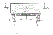
Fig. 1 and 3 is longitudinal sections of wind power plant of the present invention;
Fig. 2 and 4 is cross-sectional figure of wind power plant of the present invention.
Embodiment
Fig. 1 shows the thermal source 1 that is arranged in the cabin 2.Cabin 2 is positioned on a tower wind power plant, unshowned in the drawings.Thermal source 1 especially can be generator or other unshowned in the drawings electrical equipment, for example the current transformer of generator, contact ring cavity.In the generator that is not shown specifically, the laminated core of stator and/or rotor radially and/or axially includes air-flow path in known manner.In addition, the air of primary cooling circuit flows through the air gap of generator.
One tube bank, 6 systems are housed above 2 endogenous pyrogens 1 of cabin.Preferably this system is located at the upside in cabin 2.The wind that flows through the driving rotor blade in cabin 2 is crossed tube bank 6 along the tube bank axial flow.At this, wind flows into system at tube bank 6 inlet 4 places, is heated the back and flows out from restraining 6 outlet 5.Formed transfer of heat at tube bank 6 inlet 4 with between exporting 5, the heat that is about to contain in this thermal source 1 primary cooling circuit air is relayed in the described wind that scanned described tube bank 6 systems.In this case, flow in the system of tube bank 6 through exhaust port (Ausgang) 7, be cooled there and be transferred back described thermal source 1 again by convection current and/or ventilator 8 from the heated air of thermal source 1.Transition zone 10 expression primary cooling circuits and be designed to transition region between the tube bank 6 of heat exchanger.
Fig. 2 shows the deployment scenarios of tube bank 6 in cabin 2.Each root pipe of tube bank 6 is all cylindrical.In order to improve cooling effectiveness, preferably make these pipes have the structure that adds large surface area.In addition, can make axially paralleling of tube bank 6 according to the orientation of the wind power plant rotor blade that is not shown specifically by rotating cabin 2 with wind direction.Thereby the air mass flow that flows through tube bank 6 increases, thereby has improved cooling effectiveness.
Fig. 3 shows the thermal source 1 in the another kind of mode of execution, and its exhaust port 7 has the pipeline section 9 of lug form in the outside in cabin, and turns back in the thermal source 1 through sending into mouth 3.The heat transmission of this primary cooling circuit realizes by natural convection and/or ventilator 8 equally.Tubular sections 9 also can be assembled in the erecting bed by each parts.
Fig. 4 arranges that with the cross-sectional principle that illustrates the primary cooling circuit pipe-line system of thermal source 1 its pipeline is arranged in wind and preferably adds macrostructure with the surface area that is not shown specifically to be realized.In the primary cooling circuit convection current of heated air can exhaust port 7 be set by the top in the cabin and at the middle part in cabin or the bottom pipeline is set sends into mouthfuls 3 and realize.
Compare wind power plant of the present invention with the cooling system of up to now wind power plant Structure have the following advantages: need not to adopt the water that comprises for the air-water cooling device of generator Intermediate loop; Carry in narrow and small cabin by outer setting one air-air cooler at thermal source 1 Supplied the space; Compare with traditional system, its operational reliability improves greatly, has reduced simultaneously maintenance Expense; Do not need to provide cooling water, do not need cooling water is carried out water treatment and monitoring yet; Can economize Go the energy consumption such as the secondary device of water pump, supervising device and so on; Available primary cooling circuit also Heated air heating cabin 2; Equally, can also turn to the heated air heating of primary cooling circuit Blades, thereby especially avoid icing in winter. In addition, preferred requirement arranges fan, to realize institute The air circulation motion that requires.
Equally, compare with traditional wind power plant to break-through wind, difference of the present invention together Sample is to have very high operational reliability, because there is not the air of malaria and saliferous to flow into electricity The running space of gas equipment.
Claims (11)
1. wind power plant, it comprises
-one cabin (2), this cabin (2) are arranged to turn, so that it is along the wind direction orientation,
-being arranged on the generator (1) in this cabin (2), it comprises the primary cooling circuit of a closure,
-the wind turbine that links to each other with described cabin (2), it has at least one by wind-driven rotor blade, is used to drive described generator for electricity generation,
-one secondary cooling loop that links to each other with described cabin (2), this secondary cooling loop comprises an air-cooler, this secondary air cooler is designed to be installed in tube bank on the cabin or a cabin part, so that the rotation by described cabin (2) is along the wind direction orientation, this secondary cooling loop is flow through by the hot air that circulates that described primary cooling circuit is produced when cooled electric generator (1), with the hot air of cooling from described primary cooling circuit.
2. according to the described wind power plant of claim 1, it is characterized in that: described secondary cooling loop and described primary cooling circuit form an air-air cooler.
3. according to the described wind power plant of claim 2, it is characterized in that: described air-air cooler is in the primary side closure, and is then open in primary side.
4. according to claim 1 or 2 described wind power plants, it is characterized in that: realize heat exchange between the described primary and secondary cooling circuit by means of a heat exchanger that is designed to tube bank (6).
5. according to the described wind power plant of claim 4, it is characterized in that: described tube bank (6) parallels ground with the wind-force direction directed.
6. according to each described wind power plant in the claim 1 to 3, it is characterized in that: outlet of described secondary air cooler (5) and/or inlet (4) are set at a position that helps flowing in this cabin.
7. according to claim 1 or 2 described wind power plants, it is characterized in that: described cabin (2) constitute at least a portion in described secondary cooling loop by the pipeline section (9) of at least one lug form, thereby form a heat exchanger.
8. according to the described wind power plant of claim 1, it is characterized in that: the first half of (2) flows out in the cabin in the exhaust of described primary air cooler, and flow back into below the first half in the described cabin (2).
9. according to each described wind power plant in the claim 1 to 3, it is characterized in that: the natural convection of described primary circuit is subjected to the support of ventilator.
10. according to each described wind power plant in the claim 1 to 3, it is characterized in that: can heat described cabin (2), rotor blade by the exhaust of having heated of described primary circuit.
11. according to the described wind power plant of claim 4, it is characterized in that: the pipeline section (9) of the pipe of described tube bank or described lug form has the structure that adds large surface area.
Applications Claiming Priority (2)
| Application Number | Priority Date | Filing Date | Title |
|---|---|---|---|
| DE10233947.3 | 2002-07-25 | ||
| DE10233947A DE10233947A1 (en) | 2002-07-25 | 2002-07-25 | Wind power system has generator in gondola, turbine with rotor blade(s); generator has a closed primary cooling circuit; the gondola has an arrangement enabling cooling of primary cooling circuit |
Publications (2)
| Publication Number | Publication Date |
|---|---|
| CN1666020A CN1666020A (en) | 2005-09-07 |
| CN100416094C true CN100416094C (en) | 2008-09-03 |
Family
ID=30128403
Family Applications (1)
| Application Number | Title | Priority Date | Filing Date |
|---|---|---|---|
| CNB038162598A Expired - Fee Related CN100416094C (en) | 2002-07-25 | 2003-07-11 | Wind power installation with separate primary and secondary cooling circuits |
Country Status (6)
| Country | Link |
|---|---|
| US (2) | US7057305B2 (en) |
| EP (1) | EP1525396B2 (en) |
| CN (1) | CN100416094C (en) |
| DE (2) | DE10233947A1 (en) |
| ES (1) | ES2290535T5 (en) |
| WO (1) | WO2004016945A1 (en) |
Cited By (1)
| Publication number | Priority date | Publication date | Assignee | Title |
|---|---|---|---|---|
| CN102042391A (en) * | 2009-10-09 | 2011-05-04 | 歌美飒创新技术公司 | Auxiliary refrigeration system and operating method |
Families Citing this family (102)
| Publication number | Priority date | Publication date | Assignee | Title |
|---|---|---|---|---|
| DE10139556A1 (en) * | 2001-08-10 | 2003-02-27 | Aloys Wobben | Device for dehumidifying a gaseous medium and wind turbine with such a device |
| ITBZ20010043A1 (en) * | 2001-09-13 | 2003-03-13 | High Technology Invest Bv | ELECTRIC GENERATOR OPERATED BY WIND ENERGY. |
| DE10145414B4 (en) * | 2001-09-14 | 2013-09-12 | Aloys Wobben | Method for constructing a wind energy plant, wind energy plant |
| AU2004207180C1 (en) * | 2003-02-01 | 2010-03-25 | Aloys Wobben | Method for the erection of a wind energy plant and wind energy plant |
| DE10324228B4 (en) * | 2003-05-28 | 2006-02-16 | Rittal Gmbh & Co. Kg | Cooling device for an offshore wind turbine |
| US7431567B1 (en) * | 2003-05-30 | 2008-10-07 | Northern Power Systems Inc. | Wind turbine having a direct-drive drivetrain |
| DE10351844A1 (en) * | 2003-11-06 | 2005-06-09 | Alstom | Wind power plant for producing electricity has electrical components connected to radiator projecting through cutout in shell of gondola |
| DE102004018758A1 (en) * | 2004-04-16 | 2005-11-03 | Klinger, Friedrich, Prof. Dr.-Ing. | Tower head of a wind turbine |
| US7075192B2 (en) * | 2004-04-19 | 2006-07-11 | Northern Power Systems, Inc. | Direct drive wind turbine |
| DE102004064007B4 (en) | 2004-09-24 | 2009-08-20 | Aloys Wobben | Wind turbine with a generator cooling |
| US7633177B2 (en) * | 2005-04-14 | 2009-12-15 | Natural Forces, Llc | Reduced friction wind turbine apparatus and method |
| DE102005025944B4 (en) * | 2005-06-06 | 2008-01-31 | Siemens Ag | Wind turbine |
| JP2007002773A (en) * | 2005-06-24 | 2007-01-11 | Fuji Heavy Ind Ltd | Horizontal shaft wind mill |
| US7298055B2 (en) * | 2005-07-15 | 2007-11-20 | Abb Technology Ag | Auxiliary power supply for a wind turbine |
| US7443066B2 (en) * | 2005-07-29 | 2008-10-28 | General Electric Company | Methods and apparatus for cooling wind turbine generators |
| ATE461366T1 (en) | 2005-09-21 | 2010-04-15 | High Technology Invest Bv | BEARING SEAL ARRANGEMENT WITH LABYRINTH SEAL AND SCREW SEAL COMBINATION |
| ITBZ20050063A1 (en) | 2005-11-29 | 2007-05-30 | High Technology Invest Bv | LAMIERINI PACKAGE FOR GENERATORS AND ELECTRIC MOTORS AND PROCEDURE FOR ITS IMPLEMENTATION |
| ITBZ20050062A1 (en) | 2005-11-29 | 2007-05-30 | High Technology Invest Bv | PERMANENT MAGNET ROTOR FOR GENERATORS AND ELECTRIC MOTORS |
| US7168251B1 (en) * | 2005-12-14 | 2007-01-30 | General Electric Company | Wind energy turbine |
| EP2126351B1 (en) * | 2007-01-31 | 2014-05-07 | Vestas Wind Systems A/S | Wind energy converter with dehumidifier |
| ATE476863T1 (en) * | 2007-02-14 | 2010-08-15 | Vestas Wind Sys As | SYSTEM FOR RECIRCULATION OF AIR IN A COMPONENT OF A WIND TURBINE |
| WO2008131766A2 (en) * | 2007-04-30 | 2008-11-06 | Vestas Wind Systems A/S | A wind turbine, a method for controlling the temperature of fluid flowing in a first temperature control system of a wind turbine and use |
| JP4796009B2 (en) * | 2007-05-18 | 2011-10-19 | 三菱重工業株式会社 | Wind power generator |
| ES2330491B1 (en) * | 2007-05-25 | 2010-09-14 | GAMESA INNOVATION & TECHNOLOGY, S.L. | AIR CONDITIONING SYSTEM FOR AEROGENERATORS. |
| SE532463C2 (en) * | 2007-06-11 | 2010-01-26 | Vertical Wind Ab | Wind turbines, pillars for the same and use of the same |
| DE102007030494A1 (en) * | 2007-06-30 | 2009-01-02 | Nordex Energy Gmbh | A method for starting a wind turbine after a break in operation and wind turbine that can perform the method |
| DE102007042338A1 (en) * | 2007-09-06 | 2009-03-12 | Siemens Ag | Wind turbine with heat exchanger system |
| CN101925742B (en) * | 2007-12-21 | 2012-11-14 | 维斯塔斯风力系统集团公司 | Wind turbine generator with heat exchanger |
| US7997855B2 (en) * | 2008-01-29 | 2011-08-16 | General Electric Company | Lubrication heating system and wind turbine incorporating same |
| JP2009250214A (en) * | 2008-04-10 | 2009-10-29 | Mitsubishi Heavy Ind Ltd | Fan device for wind-driven electric power generation device and wind-driven electric power generation device |
| ITMI20081122A1 (en) | 2008-06-19 | 2009-12-20 | Rolic Invest Sarl | WIND GENERATOR PROVIDED WITH A COOLING SYSTEM |
| IT1390758B1 (en) | 2008-07-23 | 2011-09-23 | Rolic Invest Sarl | WIND GENERATOR |
| JP5123780B2 (en) * | 2008-07-28 | 2013-01-23 | 三菱重工業株式会社 | Wind power generator |
| PL2151833T3 (en) | 2008-08-07 | 2013-08-30 | Starkstrom Geraetebau Gmbh | Transformer system |
| KR101021333B1 (en) | 2008-09-01 | 2011-03-14 | 두산중공업 주식회사 | Nacelle Cooling System of Wind Turbine |
| US8047774B2 (en) * | 2008-09-11 | 2011-11-01 | General Electric Company | System for heating and cooling wind turbine components |
| DE102008050848A1 (en) | 2008-10-08 | 2010-04-15 | Wobben, Aloys | ring generator |
| IT1391939B1 (en) * | 2008-11-12 | 2012-02-02 | Rolic Invest Sarl | WIND GENERATOR |
| IT1391770B1 (en) | 2008-11-13 | 2012-01-27 | Rolic Invest Sarl | WIND GENERATOR FOR THE GENERATION OF ELECTRICITY |
| AU2009337789B2 (en) | 2009-01-14 | 2013-06-13 | Amsc Windtec Gmbh | Generator, nacelle, and mounting method of a nacelle of a wind energy converter |
| EP2391824B1 (en) | 2009-01-30 | 2017-10-25 | Vestas Wind Systems A/S | Wind turbine nacelle with cooler top |
| IT1392804B1 (en) | 2009-01-30 | 2012-03-23 | Rolic Invest Sarl | PACKAGING AND PACKAGING METHOD FOR POLE OF WIND GENERATORS |
| EP2391823B1 (en) | 2009-01-30 | 2017-09-20 | Vestas Wind Systems A/S | Wind turbine with cooler top |
| US9039368B2 (en) | 2009-01-30 | 2015-05-26 | Vestas Wind Systems A/S | Wind turbine nacelle with cooler top |
| IT1393937B1 (en) | 2009-04-09 | 2012-05-17 | Rolic Invest Sarl | WIND TURBINE |
| IT1393707B1 (en) | 2009-04-29 | 2012-05-08 | Rolic Invest Sarl | WIND POWER PLANT FOR THE GENERATION OF ELECTRICITY |
| IT1394723B1 (en) | 2009-06-10 | 2012-07-13 | Rolic Invest Sarl | WIND POWER PLANT FOR THE GENERATION OF ELECTRICITY AND ITS CONTROL METHOD |
| US20100326049A1 (en) * | 2009-06-25 | 2010-12-30 | Honeywell International Inc. | Cooling systems for rotorcraft engines |
| EP2453135B1 (en) * | 2009-07-09 | 2014-12-24 | Mitsubishi Heavy Industries, Ltd. | Wind power generator |
| IT1395148B1 (en) | 2009-08-07 | 2012-09-05 | Rolic Invest Sarl | METHOD AND APPARATUS FOR ACTIVATION OF AN ELECTRIC MACHINE AND ELECTRIC MACHINE |
| WO2011029488A1 (en) | 2009-09-11 | 2011-03-17 | Abb Research Ltd | Transformer comprising a heat pipe |
| US7837126B2 (en) * | 2009-09-25 | 2010-11-23 | General Electric Company | Method and system for cooling a wind turbine structure |
| IT1397081B1 (en) | 2009-11-23 | 2012-12-28 | Rolic Invest Sarl | WIND POWER PLANT FOR THE GENERATION OF ELECTRICITY |
| US7723859B1 (en) * | 2009-11-24 | 2010-05-25 | General Electric Company | Wind turbine with direct-connected variable speed blower |
| ES2582215T3 (en) * | 2009-12-01 | 2016-09-09 | Vestas Wind Systems A/S | Wind turbine gondola comprising a heat exchanger assembly |
| JP5318740B2 (en) * | 2009-12-11 | 2013-10-16 | 株式会社日立製作所 | Offshore windmill |
| DE102010000756A1 (en) * | 2010-01-08 | 2011-07-14 | Wobben, Aloys, 26607 | Wind turbine |
| IT1398060B1 (en) | 2010-02-04 | 2013-02-07 | Wilic Sarl | PLANT AND METHOD OF COOLING OF AN ELECTRIC GENERATOR OF AN AIR SPREADER, AND AIRCONDITIONER INCLUDING SUCH A COOLING PLANT |
| DE102010002203B4 (en) * | 2010-02-22 | 2014-05-15 | Senvion Se | Method for operating a wind energy plant |
| JP5072994B2 (en) * | 2010-03-17 | 2012-11-14 | 三菱重工業株式会社 | Wind power generator |
| IT1399201B1 (en) | 2010-03-30 | 2013-04-11 | Wilic Sarl | AEROGENERATOR AND METHOD OF REMOVING A BEARING FROM A AIRCONDITIONER |
| IT1399511B1 (en) | 2010-04-22 | 2013-04-19 | Wilic Sarl | ELECTRIC GENERATOR FOR A VENTILATOR AND AEROGENER EQUIPPED WITH THIS ELECTRIC GENERATOR |
| DE202010009461U1 (en) * | 2010-06-23 | 2010-09-16 | Nordex Energy Gmbh | Device for heating weather masts |
| JP5463218B2 (en) * | 2010-06-30 | 2014-04-09 | 三菱重工業株式会社 | Wind power generator |
| CN101949367B (en) * | 2010-09-26 | 2012-08-22 | 浙江银轮机械股份有限公司 | Pipe belt type wind turbine air cooler |
| US7963743B1 (en) * | 2010-10-16 | 2011-06-21 | Winter Curt B | Wind turbine with improved cooling |
| EP2466128B2 (en) * | 2010-12-20 | 2017-06-28 | Siemens Aktiengesellschaft | Wind turbine and method of control of a wind turbine |
| AU2011201772A1 (en) | 2011-01-28 | 2012-08-23 | Mitsubishi Heavy Industries, Ltd. | Wind turbine generator |
| ITMI20110377A1 (en) | 2011-03-10 | 2012-09-11 | Wilic Sarl | ROTARY ELECTRIC MACHINE FOR AEROGENERATOR |
| ITMI20110376A1 (en) | 2011-03-10 | 2012-09-11 | Wilic Sarl | FLUID COOLED AIRBRUSHER |
| ITMI20110378A1 (en) | 2011-03-10 | 2012-09-11 | Wilic Sarl | ROTARY ELECTRIC MACHINE FOR AEROGENERATOR |
| ITMI20110375A1 (en) | 2011-03-10 | 2012-09-11 | Wilic Sarl | WIND TURBINE |
| DE102011103311A1 (en) * | 2011-05-26 | 2012-11-29 | Aerodyn Engineering Gmbh | Wind energy plant with closed cooling circuit |
| EP2587052A1 (en) * | 2011-10-25 | 2013-05-01 | Ewt Ip B.V. | Wind turbine with cooling system |
| US20120133152A1 (en) * | 2011-11-29 | 2012-05-31 | Robert Gregory Wagoner | Systems and methods for cooling electrical components of wind turbines |
| CN102497052B (en) * | 2011-11-29 | 2013-05-22 | 中电电机股份有限公司 | Peripheral pipe distribution machine base structure of air-air cooling motor |
| US9062659B2 (en) * | 2011-12-02 | 2015-06-23 | Gamesa Innovation & Technology, S.L. | Nacelle thermal conditioning system for off-shore wind turbines |
| US20130202421A1 (en) * | 2012-02-08 | 2013-08-08 | Clipper Windpower, LLC. | Passive Liquid Cooling System for Inverters Utilized for Wind Turbine Applications |
| CN103291558B (en) * | 2012-03-01 | 2016-12-14 | 北京金风科创风电设备有限公司 | Cooling system of wind driven generator, method and wind power generating set |
| JP2013221416A (en) * | 2012-04-13 | 2013-10-28 | Hitachi Ltd | Wind power generator |
| ITMI20121304A1 (en) | 2012-07-25 | 2014-01-26 | Wilic Sarl | ROTOR OF A ROTATING ELECTRIC MACHINE FOR GAS MILLER AND AIRCONDITIONER INCLUDING SUCH ROTOR |
| ITMI20121301A1 (en) | 2012-07-25 | 2014-01-26 | Wilic Sarl | ACTIVE SEGMENT OF A ROTARY ELECTRIC MACHINE FOR THE AIRCONDITIONER, ROTARY ELECTRIC MACHINE, AND VENTILATOR |
| KR20150039852A (en) * | 2012-08-10 | 2015-04-13 | 유윈에너지 게엠베하 | Integrated cooling system for a nacelle of a wind turbine |
| KR101434443B1 (en) | 2012-12-27 | 2014-08-28 | 삼성중공업 주식회사 | Apparatus for nacelle air cooling using by heat exchanger |
| KR102121089B1 (en) * | 2013-02-18 | 2020-06-09 | 카티바, 인크. | Systems, devices and methods for the quality assessment of oled stack films |
| CN103726997B (en) * | 2014-01-17 | 2016-08-17 | 广东明阳风电产业集团有限公司 | A kind of cabin refrigeration system of offshore wind turbine |
| CN104564538B (en) * | 2014-12-25 | 2017-11-07 | 江苏金风科技有限公司 | Heat abstractor and wind power generating set for wind power generating set |
| EP3136549A1 (en) * | 2015-08-24 | 2017-03-01 | Siemens Aktiengesellschaft | Synchronous reluctance machine |
| DE102015120706B4 (en) | 2015-11-30 | 2018-03-22 | Aerodyn Engineering Gmbh | Air-cooled oil tank |
| CN107453546A (en) * | 2016-05-30 | 2017-12-08 | Abb技术有限公司 | Heat exchanger for motor |
| DE102016125375A1 (en) * | 2016-12-22 | 2018-06-28 | Innogy Se | TRANSMISSION STATION, METHOD AND DEVICE FOR A TRANSMISSION STATION |
| US20180241286A1 (en) * | 2017-02-22 | 2018-08-23 | General Electric Company | Cooling apparatus for an electric machine |
| DE102018202691A1 (en) * | 2017-04-05 | 2018-10-11 | Siemens Wind Power A/S | Power generator arrangement with cooling system |
| CN107420273B (en) * | 2017-08-14 | 2020-09-25 | 山东中车风电有限公司 | Environment control mechanism, system and application of offshore wind generating set |
| CN107387335B (en) * | 2017-09-11 | 2018-10-23 | 北京金风科创风电设备有限公司 | Wind power generation equipment, tower barrel and method for inhibiting tower shadow effect of tower barrel |
| DK3719313T3 (en) * | 2019-04-05 | 2024-08-12 | Siemens Gamesa Renewable Energy As | COOLING DEVICE FOR A WINDMILL |
| EP3772160A1 (en) * | 2019-07-31 | 2021-02-03 | General Electric Renovables España S.L. | A stator structure |
| KR102176565B1 (en) * | 2019-08-23 | 2020-11-09 | 두산중공업 주식회사 | Wind turbine |
| CN110411250B (en) * | 2019-08-29 | 2024-07-19 | 广州市雷子克电气机械有限公司 | Plate type gas cooler |
| CN111188744B (en) * | 2020-01-16 | 2021-09-03 | 浙江大学 | Wind generating set |
| CN114696537B (en) * | 2020-12-30 | 2024-01-26 | 北京金风科创风电设备有限公司 | Cooling system for wind generating set and wind generating set |
| WO2024165832A1 (en) * | 2023-02-06 | 2024-08-15 | The University Of Nottingham | Wind turbine with integral energy storage uses rotary heat exchangers to accommodate nacelle yaw |
Citations (7)
| Publication number | Priority date | Publication date | Assignee | Title |
|---|---|---|---|---|
| US4845394A (en) * | 1987-07-17 | 1989-07-04 | Siemens Aktiengesellschaft | Electric machine with a closed cooling loop |
| US5844333A (en) * | 1996-11-12 | 1998-12-01 | Unifin International, Inc. | Device and method for cooling a motor |
| DE19802574A1 (en) * | 1998-01-23 | 1999-03-11 | Siemens Ag | Wind power generator plant |
| CN1279746A (en) * | 1997-12-08 | 2001-01-10 | 西门子公司 | Wind power plant and method for cooling generator in a wind power plant |
| WO2001021956A1 (en) * | 1999-09-24 | 2001-03-29 | Lagerwey Windturbine B.V. | Wind power generator |
| US6246134B1 (en) * | 1999-07-07 | 2001-06-12 | Siemens Westinghouse Power Corporation | Apparatus and method for applying totally enclosed air-to-air cooler to electrical power generator |
| DE10000370A1 (en) * | 2000-01-07 | 2001-07-12 | Aloys Wobben | Wind power plant with completely closed or at least partly closed cooling circuit with which heat to be abstracted from cooling circuit is transmitted to wind power plant across tower or nacelle |
Family Cites Families (17)
| Publication number | Priority date | Publication date | Assignee | Title |
|---|---|---|---|---|
| US4348604A (en) * | 1980-06-13 | 1982-09-07 | General Dynamics Corp. | Totally enclosed air cooled electrical machines |
| US4807354A (en) * | 1985-09-10 | 1989-02-28 | General Electric Company | Method of rearranging components of a dynamoelectric machine |
| US4832116A (en) * | 1987-12-02 | 1989-05-23 | Deere & Company | Heat exchanger with pressurized plenum |
| DE3828834C1 (en) * | 1988-08-25 | 1989-11-02 | Mtu Muenchen Gmbh | |
| US5796580A (en) * | 1993-04-13 | 1998-08-18 | Hitachi, Ltd. | Air-cooled information processing apparatus having cooling air fan, sub-fan, and plural separated cooling air flow channels |
| DE19524733A1 (en) * | 1995-07-07 | 1997-01-09 | Bmw Rolls Royce Gmbh | Aircraft gas turbine engine with a liquid-air heat exchanger |
| FR2788308A1 (en) * | 1999-01-07 | 2000-07-13 | Snecma | COOLING DEVICE FOR A TURBOMACHINE SPEED REDUCER |
| US6499532B1 (en) * | 1999-05-04 | 2002-12-31 | Kevin R. Williams | Electric motor cooling system |
| DE19932394C5 (en) * | 1999-07-14 | 2006-06-01 | Wobben, Aloys, Dipl.-Ing. | Wind energy plant with a closed cooling circuit |
| AU758953B2 (en) * | 1999-07-14 | 2003-04-03 | Aloys Wobben | Wind energy facility with a closed cooling circuit |
| KR100649458B1 (en) * | 1999-08-23 | 2006-11-24 | 마사이찌 기쿠치 | Power generation system |
| DE19947915A1 (en) * | 1999-10-06 | 2001-04-12 | Abb Research Ltd | Cooling system for wind power system components, feeds air flow at least partly produced by chimney effect through system in tower foot region through tower, machine room to air outlet |
| DE10016913A1 (en) * | 2000-04-05 | 2001-10-18 | Aerodyn Eng Gmbh | Offshore wind turbine with a heat exchanger system |
| US6483199B2 (en) * | 2000-04-28 | 2002-11-19 | Mitsubishi Denki Kabushiki Kaisha | Wind power generating device |
| WO2002050618A2 (en) * | 2000-12-19 | 2002-06-27 | Capstone Turbine Corporation | Microturbine/capacitor power distribution system |
| US6606860B2 (en) * | 2001-10-24 | 2003-08-19 | Mcfarland Rory S. | Energy conversion method and system with enhanced heat engine |
| GB2389174B (en) * | 2002-05-01 | 2005-10-26 | Rolls Royce Plc | Cooling systems |
-
2002
- 2002-07-25 DE DE10233947A patent/DE10233947A1/en not_active Ceased
-
2003
- 2003-07-11 ES ES03787656.2T patent/ES2290535T5/en not_active Expired - Lifetime
- 2003-07-11 EP EP03787656.2A patent/EP1525396B2/en not_active Expired - Lifetime
- 2003-07-11 DE DE50308128T patent/DE50308128D1/en not_active Expired - Lifetime
- 2003-07-11 CN CNB038162598A patent/CN100416094C/en not_active Expired - Fee Related
- 2003-07-11 WO PCT/DE2003/002355 patent/WO2004016945A1/en active IP Right Grant
-
2005
- 2005-01-24 US US11/042,836 patent/US7057305B2/en not_active Expired - Fee Related
-
2006
- 2006-03-13 US US11/374,336 patent/US7161260B2/en not_active Expired - Fee Related
Patent Citations (7)
| Publication number | Priority date | Publication date | Assignee | Title |
|---|---|---|---|---|
| US4845394A (en) * | 1987-07-17 | 1989-07-04 | Siemens Aktiengesellschaft | Electric machine with a closed cooling loop |
| US5844333A (en) * | 1996-11-12 | 1998-12-01 | Unifin International, Inc. | Device and method for cooling a motor |
| CN1279746A (en) * | 1997-12-08 | 2001-01-10 | 西门子公司 | Wind power plant and method for cooling generator in a wind power plant |
| DE19802574A1 (en) * | 1998-01-23 | 1999-03-11 | Siemens Ag | Wind power generator plant |
| US6246134B1 (en) * | 1999-07-07 | 2001-06-12 | Siemens Westinghouse Power Corporation | Apparatus and method for applying totally enclosed air-to-air cooler to electrical power generator |
| WO2001021956A1 (en) * | 1999-09-24 | 2001-03-29 | Lagerwey Windturbine B.V. | Wind power generator |
| DE10000370A1 (en) * | 2000-01-07 | 2001-07-12 | Aloys Wobben | Wind power plant with completely closed or at least partly closed cooling circuit with which heat to be abstracted from cooling circuit is transmitted to wind power plant across tower or nacelle |
Cited By (2)
| Publication number | Priority date | Publication date | Assignee | Title |
|---|---|---|---|---|
| CN102042391A (en) * | 2009-10-09 | 2011-05-04 | 歌美飒创新技术公司 | Auxiliary refrigeration system and operating method |
| CN102042391B (en) * | 2009-10-09 | 2016-02-24 | 歌美飒创新技术公司 | Auxiliary cooling system and operating method thereof |
Also Published As
| Publication number | Publication date |
|---|---|
| US7057305B2 (en) | 2006-06-06 |
| DE50308128D1 (en) | 2007-10-18 |
| EP1525396B2 (en) | 2017-01-18 |
| ES2290535T3 (en) | 2008-02-16 |
| WO2004016945A1 (en) | 2004-02-26 |
| DE10233947A1 (en) | 2004-02-12 |
| US20050167989A1 (en) | 2005-08-04 |
| US20060145484A1 (en) | 2006-07-06 |
| EP1525396B1 (en) | 2007-09-05 |
| US7161260B2 (en) | 2007-01-09 |
| ES2290535T5 (en) | 2017-07-07 |
| EP1525396A1 (en) | 2005-04-27 |
| CN1666020A (en) | 2005-09-07 |
Similar Documents
| Publication | Publication Date | Title |
|---|---|---|
| CN100416094C (en) | Wind power installation with separate primary and secondary cooling circuits | |
| US6676122B1 (en) | Wind energy facility with a closed cooling circuit | |
| US7168251B1 (en) | Wind energy turbine | |
| EP2570660B1 (en) | Renewable energy type electric power generation device | |
| US8640478B2 (en) | Nacelle cooling system for wind turbine | |
| US20030182944A1 (en) | Highly supercharged gas-turbine generating system | |
| US20160145837A1 (en) | Wind Qanat, an Apparatus for Atmospheric Moisture Recovery | |
| EP1318299A1 (en) | Bulb turbine-generator unit | |
| ITMI941519A1 (en) | METHOD AND APPARATUS FOR INCREASING THE POWER PRODUCED BY GAS TURBINE | |
| CN108266337A (en) | wind generating set and cooling method thereof | |
| AU2011236050B2 (en) | Steam turbine plant | |
| WO2013104777A2 (en) | Cooling system of a wind turbine | |
| TWI630316B (en) | Wind power generator | |
| GB2364553A (en) | Operating a steam/gas turbine plant | |
| JPH1198767A (en) | Cooler for generator | |
| MXPA05005297A (en) | System and method for water pasteurization and power generation. | |
| JP2019527029A (en) | Method for cooling the rotor of a generator | |
| CN109184814A (en) | A kind of steam turbine of achievable pure condensate and back pressure heat supply switchover operation | |
| KR102429086B1 (en) | Electric-hydraulic cogeneration system with wind | |
| KR20130001185U (en) | Outside air introducing apparatus | |
| AU2014202430B2 (en) | Steam Turbine Plant | |
| FI78176B (en) | FOERFARANDE OCH ANORDNING FOER UTNYTTJANDE AV VAERMEENERGI SOM FRIGOERS I KYLPROCESS. | |
| CN113090478A (en) | Wind generating set, environment control system and environment control method | |
| CA1070959A (en) | Energy conversion device | |
| CN203572123U (en) | Circulating water cooling device |
Legal Events
| Date | Code | Title | Description |
|---|---|---|---|
| C06 | Publication | ||
| PB01 | Publication | ||
| C10 | Entry into substantive examination | ||
| SE01 | Entry into force of request for substantive examination | ||
| C14 | Grant of patent or utility model | ||
| GR01 | Patent grant | ||
| CF01 | Termination of patent right due to non-payment of annual fee |
Granted publication date: 20080903 Termination date: 20170711 |
|
| CF01 | Termination of patent right due to non-payment of annual fee |