EP1525363B1 - Latch for a mobile part of a vehicle body, such as a flap or a door, especially a rear opening - Google Patents
Latch for a mobile part of a vehicle body, such as a flap or a door, especially a rear opening Download PDFInfo
- Publication number
- EP1525363B1 EP1525363B1 EP20030766173 EP03766173A EP1525363B1 EP 1525363 B1 EP1525363 B1 EP 1525363B1 EP 20030766173 EP20030766173 EP 20030766173 EP 03766173 A EP03766173 A EP 03766173A EP 1525363 B1 EP1525363 B1 EP 1525363B1
- Authority
- EP
- European Patent Office
- Prior art keywords
- handle
- combined assembly
- housing
- latch according
- locking cylinder
- Prior art date
- Legal status (The legal status is an assumption and is not a legal conclusion. Google has not performed a legal analysis and makes no representation as to the accuracy of the status listed.)
- Expired - Fee Related
Links
Images


Classifications
-
- E—FIXED CONSTRUCTIONS
- E05—LOCKS; KEYS; WINDOW OR DOOR FITTINGS; SAFES
- E05B—LOCKS; ACCESSORIES THEREFOR; HANDCUFFS
- E05B83/00—Vehicle locks specially adapted for particular types of wing or vehicle
- E05B83/16—Locks for luggage compartments, car boot lids or car bonnets
- E05B83/18—Locks for luggage compartments, car boot lids or car bonnets for car boot lids or rear luggage compartments
-
- E—FIXED CONSTRUCTIONS
- E05—LOCKS; KEYS; WINDOW OR DOOR FITTINGS; SAFES
- E05B—LOCKS; ACCESSORIES THEREFOR; HANDCUFFS
- E05B85/00—Details of vehicle locks not provided for in groups E05B77/00 - E05B83/00
- E05B85/10—Handles
- E05B85/107—Pop-out handles, e.g. sliding outwardly before rotation
-
- E—FIXED CONSTRUCTIONS
- E05—LOCKS; KEYS; WINDOW OR DOOR FITTINGS; SAFES
- E05B—LOCKS; ACCESSORIES THEREFOR; HANDCUFFS
- E05B17/00—Accessories in connection with locks
- E05B17/04—Devices for coupling the turning cylinder of a single or a double cylinder lock with the bolt operating member
-
- E—FIXED CONSTRUCTIONS
- E05—LOCKS; KEYS; WINDOW OR DOOR FITTINGS; SAFES
- E05B—LOCKS; ACCESSORIES THEREFOR; HANDCUFFS
- E05B17/00—Accessories in connection with locks
- E05B17/14—Closures or guards for keyholes
-
- E—FIXED CONSTRUCTIONS
- E05—LOCKS; KEYS; WINDOW OR DOOR FITTINGS; SAFES
- E05B—LOCKS; ACCESSORIES THEREFOR; HANDCUFFS
- E05B5/00—Handles completely let into the surface of the wing
- E05B5/003—Pop-out handles, e.g. sliding outwardly before rotation
-
- E—FIXED CONSTRUCTIONS
- E05—LOCKS; KEYS; WINDOW OR DOOR FITTINGS; SAFES
- E05B—LOCKS; ACCESSORIES THEREFOR; HANDCUFFS
- E05B17/00—Accessories in connection with locks
- E05B17/14—Closures or guards for keyholes
- E05B17/18—Closures or guards for keyholes shaped as lids or slides
- E05B17/183—Closures or guards for keyholes shaped as lids or slides pivoting outwardly
-
- E—FIXED CONSTRUCTIONS
- E05—LOCKS; KEYS; WINDOW OR DOOR FITTINGS; SAFES
- E05B—LOCKS; ACCESSORIES THEREFOR; HANDCUFFS
- E05B81/00—Power-actuated vehicle locks
- E05B81/54—Electrical circuits
- E05B81/64—Monitoring or sensing, e.g. by using switches or sensors
- E05B81/76—Detection of handle operation; Detection of a user approaching a handle; Electrical switching actions performed by door handles
-
- E—FIXED CONSTRUCTIONS
- E05—LOCKS; KEYS; WINDOW OR DOOR FITTINGS; SAFES
- E05B—LOCKS; ACCESSORIES THEREFOR; HANDCUFFS
- E05B83/00—Vehicle locks specially adapted for particular types of wing or vehicle
- E05B83/16—Locks for luggage compartments, car boot lids or car bonnets
-
- E—FIXED CONSTRUCTIONS
- E05—LOCKS; KEYS; WINDOW OR DOOR FITTINGS; SAFES
- E05B—LOCKS; ACCESSORIES THEREFOR; HANDCUFFS
- E05B85/00—Details of vehicle locks not provided for in groups E05B77/00 - E05B83/00
- E05B85/10—Handles
- E05B85/103—Handles creating a completely closed wing surface
-
- Y—GENERAL TAGGING OF NEW TECHNOLOGICAL DEVELOPMENTS; GENERAL TAGGING OF CROSS-SECTIONAL TECHNOLOGIES SPANNING OVER SEVERAL SECTIONS OF THE IPC; TECHNICAL SUBJECTS COVERED BY FORMER USPC CROSS-REFERENCE ART COLLECTIONS [XRACs] AND DIGESTS
- Y10—TECHNICAL SUBJECTS COVERED BY FORMER USPC
- Y10T—TECHNICAL SUBJECTS COVERED BY FORMER US CLASSIFICATION
- Y10T70/00—Locks
- Y10T70/50—Special application
- Y10T70/5611—For control and machine elements
- Y10T70/5757—Handle, handwheel or knob
- Y10T70/5761—Retractable or flush handle
-
- Y—GENERAL TAGGING OF NEW TECHNOLOGICAL DEVELOPMENTS; GENERAL TAGGING OF CROSS-SECTIONAL TECHNOLOGIES SPANNING OVER SEVERAL SECTIONS OF THE IPC; TECHNICAL SUBJECTS COVERED BY FORMER USPC CROSS-REFERENCE ART COLLECTIONS [XRACs] AND DIGESTS
- Y10—TECHNICAL SUBJECTS COVERED BY FORMER USPC
- Y10T—TECHNICAL SUBJECTS COVERED BY FORMER US CLASSIFICATION
- Y10T70/00—Locks
- Y10T70/50—Special application
- Y10T70/5611—For control and machine elements
- Y10T70/5757—Handle, handwheel or knob
- Y10T70/5765—Rotary or swinging
- Y10T70/577—Locked stationary
- Y10T70/5792—Handle-carried key lock
-
- Y—GENERAL TAGGING OF NEW TECHNOLOGICAL DEVELOPMENTS; GENERAL TAGGING OF CROSS-SECTIONAL TECHNOLOGIES SPANNING OVER SEVERAL SECTIONS OF THE IPC; TECHNICAL SUBJECTS COVERED BY FORMER USPC CROSS-REFERENCE ART COLLECTIONS [XRACs] AND DIGESTS
- Y10—TECHNICAL SUBJECTS COVERED BY FORMER USPC
- Y10T—TECHNICAL SUBJECTS COVERED BY FORMER US CLASSIFICATION
- Y10T70/00—Locks
- Y10T70/50—Special application
- Y10T70/5889—For automotive vehicles
- Y10T70/5903—Hood
-
- Y—GENERAL TAGGING OF NEW TECHNOLOGICAL DEVELOPMENTS; GENERAL TAGGING OF CROSS-SECTIONAL TECHNOLOGIES SPANNING OVER SEVERAL SECTIONS OF THE IPC; TECHNICAL SUBJECTS COVERED BY FORMER USPC CROSS-REFERENCE ART COLLECTIONS [XRACs] AND DIGESTS
- Y10—TECHNICAL SUBJECTS COVERED BY FORMER USPC
- Y10T—TECHNICAL SUBJECTS COVERED BY FORMER US CLASSIFICATION
- Y10T70/00—Locks
- Y10T70/80—Parts, attachments, accessories and adjuncts
- Y10T70/8432—For key-operated mechanism
- Y10T70/8649—Keyhole covers
Definitions
- the invention is directed to a closure of the kind specified in the preamble of claim 1.
- a handset relative to a stationary part of the vehicle body is movable and that is normally pivotable between a closed position and an open position of the handset.
- the closed position of the handset is secured by a lock.
- Such locks are normally operated electrically and / or by a remote control. In an emergency, however, if the electrical control fails, the lock can be unlocked mechanically via a lock cylinder by means of an associated key.
- a handle on the handset which is movable in a vertical plane to the vehicle body. Normally, in the case of rest, the handle is in its Zuklapplage, which is flush with the vehicle body and thereby protects the lock cylinder. To be able to open the handset manually, the handle is transferred to an outstanding Aufklapplage. Then it can be easily grasped behind to open the handset of the vehicle. In an emergency, the lock cylinder for the key is accessible in the Aufklapplage.
- the lock cylinder is fixedly integrated in a housing which is installed in a tailgate of a vehicle.
- the housing opening is normally closed by a cover which is hingedly movable about an axis parallel to the plane of the cover. In its Aufklapplage the cover acts as a handle for opening the tailgate.
- the stationary lock cylinder is oriented with its cylinder axis in the direction of the housing opening.
- the output of the dormant lock cylinder is permanently coupled to the lock, in order to transfer in an emergency by the inserted key the lock between its safety position and arming position.
- the lock cylinder must have a considerable cylinder length in order to position the required plurality of tumblers axially next to one another. This brings an undesirably large depth in the already very tight space in the area of a tailgate.
- lid lock for a trunk lid known ( DE 802 046 ) consists of two directly adjacent lock parts, which overlap the gap between the movable trunk lid and the stationary Kofferrau.mveritate.
- the seated on the panel lock part has a spring-loaded latch, which engages over a bottom plate of the adjacent lock part sitting on the boot lid.
- At the bottom plate of the actual handle is pivotally mounted and spring-loaded in the direction of its investment position.
- a lock cylinder is mitbeweglich with the handle, but sits its entrance opening for the lock cylinder on the show side of the handle. As a result, the lock cylinder is accessible both in the investment position as well as in the storage position of the handle of the key and therefore always unprotected.
- the lock cylinder can therefore easily become dirty and thus unusable.
- the lock cylinder only serves to secure the handle in its abutment position on the bottom plate. An emergency situation is not planned.
- the lock cylinder In order to pivot the handle in the Abrageposition, the lock cylinder must be operated by the key. During this pivoting movement, the bolt of the adjacent lock part is pressed far enough away from a profile edge on the handle of the cover-side lock part so that it releases the bottom plate.
- the cover does not serve as a handle for opening a handset, but as a rocker switch for electromotive opening the handset.
- a lock cylinder is arranged, which points in the Zuklappposition of the cover into the interior of the handset.
- the cover is pivotally mounted in its center about a horizontal axis and is held by a spring in its cover. The cover can be transferred from its cover in three different pivot positions. If the cover acting as a rocker switch is pivoted by a small angle of 15 °, a microswitch is actuated, which opens the lock electronically. In this first pivot position of the rear lock cylinder is not accessible by the key.
- the cover can be manually pivoted over a larger angle of about 45 ° until a located at the output of the lock cylinder rotary latch abuts a resting nose in the handset. But then the key can be inserted into the lock cylinder, whereby the rotary latch is pivoted away from the nose and a mandrel on the lock cylinder in alignment with an axially movable pin in the interior of the handset comes into alignment. Then, the cover can be manually transferred further into a third pivot position, wherein the mandrel hits the pin and presses it axially. As a result, an unlocking device is mechanically actuated in the interior of the vehicle.
- the invention has for its object to develop a reliable closure of the type mentioned in the preamble of claim 1, which is designed to save space in its depth. This is inventively achieved by the measures mentioned in claim 1, which has the following special significance.
- the handle with the lock cylinder forms a jointly movable in the folding movement combination having a first member of a rotary joint.
- the combination of the rear lock cylinder is accessible to the key and when turning the lock cylinder by the key, the member is rotated, which is why it should be called “Drebkupplungsglied" below.
- a second counter member for this rotary joint is arranged at a defined location of the handset and should, upon rotation, act by its rotational movement on the lock. This second counterpart is to be referred to below as a "rotary coupling counterpart".
- the combination of the rotary coupling member is disconnected from the rotary coupling counterpart, and therefore, apart from the inaccessibility of the lock cylinder for the key, a torque between the lock cylinder and the counter element basically can not be transferred.
- the rotary joint mating member is disposed in the same vertical plane in which the rotary coupling member moves during the folding movement of the combination, in the last phase of the unfolding movement, the coupling portion of that member engages the mating coupling portion of the mating member, for which reason a key turn torque transmission the lock cylinder is possible. Therefore, in the Aufklapplage by transferring the torque, the lock can be transferred from its armed position to its secure position or vice versa.
- the lock cylinder in the Zuklapplage on the one hand and in the Aufklapplage on the other hand takes two different positions in the handset of the vehicle body.
- the lock cylinder can advantageously extend parallel to the handle, so may extend substantially in the direction of the course of the vehicle body.
- the available large height of the handle can be used to arrange a lock cylinder.
- In the direction of the handle can be arranged numerous tumblers in the lock cylinder, whereby the amount of permutations is increased.
- the lock cylinder and keys can have a very extensive code that the Breakage security of such closure improved.
- the depth direction of the handset of such closure comes out with a surprisingly small depth, which corresponds only to the cross section of the lock cylinder. Because the lock cylinder is always oriented in the direction of travel of the handle, it is accessible to the key even at relatively small Aufklappwinkel. In the Aufklapplage the locking cylinder of the combination protrudes considerably over the vehicle body.
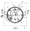
- a unit 11 is fixed, consisting of a cup-shaped housing 30 and a housing opening 31 normally closing handle 21.
- Fastening means 39 are made of Fig. 2 to recognize.
- the housing 30 is traversed by a dash-dotted lines indicated axis 15, via which the handle 21 hingedly movable in the housing in the direction of the arrow 25 of Fig. 3 is stored.
- This axis 15 will be referred to hereinafter as "folding axis".
- the folding movement takes place in the drawing planes of Fig. 3 and 8th , It follows that this folding movement 25 takes place in a vertical plane to the course of the vehicle body of the tailgate 10 at the location of the unit 11.
- Fig. 4 shows that the handle 21 is formed as a two-ply plate; it includes a base plate 22 and a curved ornamental plate 23.
- the ornamental plate 23 carries a company emblem 24.
- Firmly connected to the handle 21 is a lock cylinder 40, which therefore participates in the folding movement 25 of the handle 21.
- This assembly 20 from the handle 21 and the lock cylinder 40 is to be referred to below, as already mentioned, "combination”.
- the lock cylinder 40 is integrated into the material of the handle 21 and is located on its in Fig. 4 with 26 marked back.
- a cylinder housing 42 serves to receive the lock cylinder 40 and is formed integrally with the base plate 22 of the handle 21.
- illustrated cylinder axis 44 extends substantially parallel to the plane of the base plate 22 and lies in that vertical plane in which the folding movement 25 of the combination 20 takes place.
- the collapse situation of the combination 20 is shown what is in Fig. 3 is illustrated by the auxiliary line 20.1.
- the combination 20 is on the show side substantially flush with the body of the tailgate 10.
- the lock cylinder 20 is protected inside the housing.
- the output 43 of the lock cylinder is generally non-rotatably connected to a first member 45 of a rotary coupling via a plurality of per se known members comprehensive one-way clutch 46, whose end-side coupling point consists of the interior 47 of a fork.
- This rotary coupling member 45 is also part of the combination 20 and is moved in their folding movement 25 with. It shall be referred to as "movable rotary coupling member 45".
- This movable rotary coupling member 45 is in the housing 30 associated with a "stationary rotary coupling counter-member 35", which has a flat profile piece 37 as a coupling point. In the coupling case, the flat profile piece 37 fits into the fork interior 47 of the movable rotary coupling member 45.
- the stationary rotary coupling counter member 35 is rotatably mounted at a defined position of the housing wall 33 with a pin 36.
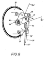
- a driver 16 engages a lock of the tailgate 10 leading link chain 50, which consists in the present case of a Bowden cable.
- the strand 51 of the Bowden cable is, as at 17 in Fig.
- Fig. 6 can be seen suspended in an end claw of the driver 16.
- the jacket 52 of the Bowden cable 50 is attached to the housing 30 at 18.
- the driver 16 takes the in Fig. 6 drawn drawn starting position, which is illustrated there by the auxiliary line 16.1.
- the aforementioned return spring 38 determines this starting position 16.1.
- Dash-dotted in Fig. 6 is also denoted by 16.2 actuating position of the driver 16. If the driver 16 is pivoted into this operating position 16.2, then the strand 51 of the Bowden cable is taken and unlocked the lock of the tailgate 10. Then the tailgate 10 can be opened as in Fig. 8 will be described in more detail.
- the flat profile piece 37 of the counter member 35 is located in the fork interior 47 of the movable rotary coupling member 45.
- the lock cylinder 40 is in the Aufklapplage 20.2 in a position where the keyhole is conveniently accessible to the key 41. If the correct key 41 is inserted in the lock cylinder 40, then a rotation leads to the described movement of the driver 60, which has an effect on the lock. A torque is transmitted between the lock cylinder and the cam 16 leading to the lock. By rotation of the inserted key 41, the lock can be adjusted between its safety position and arming position in an emergency.
- the in Fig. 8 Marked with 19 hinged angle is determined by a stop 28 on the combination 20 and a counter-stop 48 on the housing 30.
- Fig. 3 shows, still a protective sleeve 27, 29, which is also integrally formed on the base plate 22 and has a special sleeve profile.
- the sleeve has a narrow portion 27 which receives in the Zuklapplage 20.1 serving for coupling flat profile piece 37 from the stationary rotary coupling counter-member 35.
- This narrow sleeve portion 27 is particularly good Fig. 5 to recognize.
- the dimensions of this narrow sleeve portion 27 are chosen so that the flat profile piece 37 with a slight clearance just fits between them. This results in a double guiding effect.
- the flat profile piece 37 of the counter member 35 is secured in a defined rotational position.
- the narrow sleeve portion 27 has on its side facing in the direction of the folding movement a flattening 28, which justifies the above-mentioned stop for the housing-side counter stop 48.
- This counter-attack 48 arises as Fig. 3 illustrated by a stepped profile 48, 49 in the housing wall 33.
- the counter-stop 48 is as it were the tread surface of this stage.
- the impact surface 49 of the stage also has the function in the Zuklapplage 20.1 to act as a stop for the combination 20.
- This purpose is preferably a buffer 14 made of elastomeric material, which is anchored in a bore of this abutment surface 49 and cooperates with a suitable flattening 54 of the cylinder housing 42.
- the cylinder axis 44 is set against the perpendicular thereto folding axis 15 into the housing interior 32.
- the folding axis 15 is otherwise generated by two separate axle pins 12, 13, which consist of cap screws here.
- the two cap screws 12, 13 are passed from opposite sides 61, 62 of the assembly 11 through housing bores 53, where they pass through bearing sleeves 55, 56.
- the threaded parts of the two cap screws 12, 13 are anchored in threaded holes 57.
- the ends of the two tightened screws 12, 13 are at a distance 58 to each other. This spacing region 58 can be used for the arrangement of the lock cylinder 40. If the screws 12, 13 are made of steel pins, forcible tearing out is largely prevented.
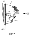
- a working arm 59 which cooperates with a micro-switch 60.
- the arm 59 is integrally formed with the one bearing sleeve 56. By tightening the cap screw 12, the rotationally fixed connection between the combination 20 and the arm 59 comes about.
- Fig. 5 shows that pin 63, which are integrally formed with the base plate 22 and project on both sides of the cylinder housing 42, serve to attach two leg springs 64.
- the torsion springs 64 are based on one end of the housing and the other on the back 26 of the combination 20 and ensure with their spring force that the combination 20 normally in its Zuklapplage 20.1 of Fig. 3 is held.
Abstract
Description
Die Erfindung richtet sich auf einen Verschluss der im Oberbegriff des Anspruches 1 angegebenen Art. Dabei ist ein Mobilteil gegenüber einem Stationärteil der Fahrzeugkarosserie beweglich und zwar normalerweise schwenkbeweglich zwischen einer Schließstellung und einer Offenstellung des Mobilteils. Die Schließstellung des Mobilteils wird dabei durch ein Schloss gesichert. Solche Schlösser werden normalerweise elektrisch und/oder durch eine Fernbedienung betätigt. Im Notfall aber, wenn die elektrische Steuerung ausfällt, kann das Schloss mechanisch über einen Schließzylinder mittels eines zugehörigen Schlüssels entsichert werden.The invention is directed to a closure of the kind specified in the preamble of claim 1. In this case, a handset relative to a stationary part of the vehicle body is movable and that is normally pivotable between a closed position and an open position of the handset. The closed position of the handset is secured by a lock. Such locks are normally operated electrically and / or by a remote control. In an emergency, however, if the electrical control fails, the lock can be unlocked mechanically via a lock cylinder by means of an associated key.
Bei diesen Verschlüssen gibt es auch eine Handhabe am Mobilteil, welche in einer Vertikalebene zur Fahrzeugkarosserie klappbeweglich ist. Normalerweise, im Ruhefall, befindet sich die Handhabe in ihrer Zuklapplage, die mit der Fahrzeugkarosserie bündig ist und den Schließzylinder dabei schützt. Um den Mobilteil manuell öffnen zu können, wird die Handhabe in eine herausragende Aufklapplage überführt. Dann kann sie bequem hintergriffen werden, um den Mobilteil des Fahrzeugs zu öffnen. Im Notfall ist in der Aufklapplage auch der Schließzylinder für den Schlüssel zugänglich.In these closures, there is also a handle on the handset, which is movable in a vertical plane to the vehicle body. Normally, in the case of rest, the handle is in its Zuklapplage, which is flush with the vehicle body and thereby protects the lock cylinder. To be able to open the handset manually, the handle is transferred to an outstanding Aufklapplage. Then it can be easily grasped behind to open the handset of the vehicle. In an emergency, the lock cylinder for the key is accessible in the Aufklapplage.
Bei dem bekannten Verschluss dieser Art (
Bei einem bekannten Verschluss anderer Art (
Es ist ein Deckelschloss für einen Kofferraumdeckel bekannt (
Der Schließzylinder kann daher leicht verschmutzen und dadurch unbrauchbar werden. Außerdem dient der Schließzylinder nur dazu, um den Griff in seiner Anlageposition an der Bodenplatte zu sichern. Eine Notsituation ist nicht vorgesehen. Um den Griff in die Abrageposition verschwenken zu können, muss der Schließzylinder vom Schlüssel betätigt werden. Bei dieser Schwenkbewegung wird der Riegel des benachbarten Schlossteils von einer Profilkante am Griff des deckelseitigen Schlossteils so weit weggedrückt, dass er die Bodenplatte freigibt.The lock cylinder can therefore easily become dirty and thus unusable. In addition, the lock cylinder only serves to secure the handle in its abutment position on the bottom plate. An emergency situation is not planned. In order to pivot the handle in the Abrageposition, the lock cylinder must be operated by the key. During this pivoting movement, the bolt of the adjacent lock part is pressed far enough away from a profile edge on the handle of the cover-side lock part so that it releases the bottom plate.
Bei einem Verschluss gemäß der nicht vorveröffentlichten
Der Erfindung liegt die Aufgabe zugrunde, einen zuverlässigen Verschluss der im Oberbegriff des Anspruches 1 genannten Art zu entwickeln, der in seiner Bautiefe platzsparend ausgebildet ist. Dies wird erfindungsgemäß durch die im Anspruch 1 genannten Maßnahmen erreicht, denen folgende besondere Bedeutung zukommt.The invention has for its object to develop a reliable closure of the type mentioned in the preamble of claim 1, which is designed to save space in its depth. This is inventively achieved by the measures mentioned in claim 1, which has the following special significance.
Bei der Erfindung bildet die Handhabe mit dem Schließzylinder eine gemeinsam bei der Klappbewegung bewegliche Kombination, die ein erstes Glied einer Drehkupplung aufweist. In der Aufklapplage der Kombination ist der rückseitige Schließzylinder für den Schlüssel zugänglich und beim Drehen des Schließzylinders durch den Schlüssel wird das Glied mitgedreht, weshalb es nachfolgend "Drebkupplungs-Glied" genannt werden soll. Ein zweites Gegenglied für diese Drehkupplung ist an einem definierten Ort des Mobilteils angeordnet und soll, bei Drehung, durch seine Drehbewegung auf das Schloss einwirken. Dieses zweite Gegenglied soll nachfolgend als "Drehkupplungs-Gegenglied" bezeichnet werden.In the invention, the handle with the lock cylinder forms a jointly movable in the folding movement combination having a first member of a rotary joint. In the Aufklapplage the combination of the rear lock cylinder is accessible to the key and when turning the lock cylinder by the key, the member is rotated, which is why it should be called "Drebkupplungsglied" below. A second counter member for this rotary joint is arranged at a defined location of the handset and should, upon rotation, act by its rotational movement on the lock. This second counterpart is to be referred to below as a "rotary coupling counterpart".
Normalerweise, in Zuklapplage der Kombination, ist das an der Kombination befindliche Drehkupplungs-Glied vom Drehkupplungs-Gegenglied entkuppelt, weshalb, abgesehen von der Unzugänglichkeit des Schließzylinders für den Schlüssel, ein Drehmoment zwischen dem Schließzylinder und dem Gegenglied grundsätzlich nicht übertragen werden kann. Weil das Drehkupplungs-Gegenglied in der gleichen Vertikalebene angeordnet ist, in welcher sich das Drehkupplungs-Glied bei der Klappbewegung der Kombination bewegt, fährt in der letzten Phase der Aufklappbewegung der Kupplungsbereich dieses Glieds in den Gegenkupplungsbereich des Gegenglieds ein, weshalb dann eine DrehmomentÜbertragung durch Schlüsseldrehung des Schließzylinders möglich ist. Daher kann in der Aufklapplage durch die Übertragung des Drehmoments das Schloss aus seiner Entsicherungsposition in seine Sicherungsposition oder umgekehrt überführt werden.Normally, in Zuklapplage the combination, the combination of the rotary coupling member is disconnected from the rotary coupling counterpart, and therefore, apart from the inaccessibility of the lock cylinder for the key, a torque between the lock cylinder and the counter element basically can not be transferred. Because the rotary joint mating member is disposed in the same vertical plane in which the rotary coupling member moves during the folding movement of the combination, in the last phase of the unfolding movement, the coupling portion of that member engages the mating coupling portion of the mating member, for which reason a key turn torque transmission the lock cylinder is possible. Therefore, in the Aufklapplage by transferring the torque, the lock can be transferred from its armed position to its secure position or vice versa.
Bei der Erfindung nimmt also der Schließzylinder in der Zuklapplage einerseits und in der Aufklapplage andererseits zwei unterschiedliche Positionen im Mobilteil der Fahrzeugkarosserie ein. In der Zuklapplage kann der Schließzylinder zweckmäßigerweise parallel zur Handhabe verlaufen, kann sich also im wesentlichen in Richtung des Verlaufs der Fahrzeugkarosserie erstrecken. Die verfügbare große Höhe der Handhabe kann zur Anordnung eines Schließzylinders genutzt werden. In Verlaufsrichtung der Handhabe kann man zahlreiche Zuhaltungen im Schließzylinder anordnen, womit die Menge der Permutationen erhöht wird. Der Schließzylinder und Schlüssel können einen sehr umfangreichen Code aufweisen, der die Aufbruchsicherheit des derartigen Verschlusses verbessert. In Tiefenrichtung des Mobilteils kommt der derartige Verschluss mit einer überraschend kleinen Bautiefe aus, die nur dem Querschnitt des Schließzylinders entspricht. Weil der Schließzylinder stets in Verlaufsrichtung der Handhabe orientiert ist, ist er für den Schlüssel bereits bei verhältnismäßig kleinem Aufklappwinkel zugänglich. In der Aufklapplage ragt der Schließzylinder der Kombination beträchtlich über die Fahrzeugkarosserie heraus.In the invention, therefore, the lock cylinder in the Zuklapplage on the one hand and in the Aufklapplage on the other hand takes two different positions in the handset of the vehicle body. In the Zuklapplage the lock cylinder can advantageously extend parallel to the handle, so may extend substantially in the direction of the course of the vehicle body. The available large height of the handle can be used to arrange a lock cylinder. In the direction of the handle can be arranged numerous tumblers in the lock cylinder, whereby the amount of permutations is increased. The lock cylinder and keys can have a very extensive code that the Breakage security of such closure improved. In the depth direction of the handset of such closure comes out with a surprisingly small depth, which corresponds only to the cross section of the lock cylinder. Because the lock cylinder is always oriented in the direction of travel of the handle, it is accessible to the key even at relatively small Aufklappwinkel. In the Aufklapplage the locking cylinder of the combination protrudes considerably over the vehicle body.
Weitere Maßnahmen und Vorteile der Erfindung ergeben sich aus den Unteransprüchen, der nachfolgenden Beschreibung und den Zeichnungen. In den Zeichnungen ist die Erfindung in einem Ausführungsbeispiel dargestellt. Es zeigen:
- Fig. 1
- die Draufsicht auf ein Teilstück einer als Mobilteil fungierenden Heckklappe einer Fahrzeugkarosserie mit Blick auf die Handhabe, wenn sich diese in ihrer Zuklapplage befindet,
- Fig. 2,
- vor dem Einbau in die strichpunktiert angedeutete Heckklappe, den Verschluss von
Fig. 1 mit Blick auf seine Rückseite, - Fig. 3
- einen Längsschnitt durch den Verschluss längs der Schnittlinie III - III von
Fig. 1 , - Fig. 4 + 5
- zwei Querschnitte durch den in
Fig. 2 gezeigten Verschluss längs der dortigen Schnittlinien IV - IV bzw. V - V, - Fig. 6
- eine perspektivische Rückansicht des in
Fig. 2 gezeigten Verschlusses, wobei das Anfangsstück eines Bowdenzuges gezeigt ist, der Bestandteil einer zum nicht näher gezeigten Schloss der Heckklappe führenden Gliederkette ist, - Fig. 7
- zeigt eine Seitenansicht eines Ausführungsbeispiels des erfindungsgemäßen Verschlusses in Blickrichtung des Pfeiles VII von
Fig. 2 und - Fig.8
- einen der
Fig. 3 entsprechenden Längsschnitt durch den Verschluss, wenn sich die Handhabe in ihrer Aufklapplage befindet und der mit ihr klappbewegliche Schließzylinder für einen Schlüssel zugänglich ist.
- Fig. 1
- the top view of a portion of a function as a tailgate tailgate of a vehicle body with a view of the handle when it is in its Zuklapplage
- 2,
- prior to installation in the dash-dotted line indicated tailgate, the closure of
Fig. 1 facing his back, - Fig. 3
- a longitudinal section through the closure along the section line III - III of
Fig. 1 . - Fig. 4 + 5
- two cross sections through the in
Fig. 2 shown closure along the section lines IV - IV and V - V, - Fig. 6
- a perspective rear view of the in
Fig. 2 shown closure, wherein the initial part of a Bowden cable is shown, which is part of a chain of links leading to the lock of the tailgate, not shown in detail, - Fig. 7
- shows a side view of an embodiment of the closure according to the invention in the direction of arrow VII of
Fig. 2 and - Figure 8
- one of the
Fig. 3 corresponding longitudinal section through the closure when the handle is in its Aufklapplage and accessible with her folding lock cylinder for a key.
In den Zeichnungen ist lediglich ein Bruchstück einer als Mobilteil der Karosserie dienende Heckklappe 10 gezeigt. In der Heckklappe 10 ist eine Baueinheit 11 befestigt, bestehend aus einem schalenförmigen Gehäuse 30 und einer die Gehäuseöffnung 31 normalerweise verschließenden Handhabe 21. Befestigungsmittel 39 dafür sind aus
Aus
Der Ausgang 43 des Schließzylinders ist über eine mehrere an sich bekannte Glieder umfassende Freilaufkupplung 46 normalerweise drehfest mit einem ersten Glied 45 einer Drehkupplung verbunden, dessen endseitige Kuppelstelle aus dem Innenraum 47 einer Gabel besteht. Dieses Drehkupplungs-Glied 45 ist ebenfalls Bestandteil der Kombination 20 und wird bei deren Klappbewegung 25 mit bewegt. Es soll "bewegliches Drehkupplungs-Glied 45" bezeichnet werden.The
Diesem beweglichen Drehkupplungs-Glied 45 ist im Gehäuse 30 ein "ruhendes Drehkupplungs-Gegenglied 35" zugeordnet, welches als Kuppelstelle ein Flachprofilstück 37 besitzt. Im Kupplungsfall passt das Flachprofilstück 37 in den Gabelinnenraum 47 des beweglichen Drehkupplungs-Glied 45 hinein. Das ruhende Drehkupplungs-Gegenglied 35 ist an einer definierten Stelle der Gehäusewand 33 mit einem Zapfen 36 drehbar gelagert. Auf der Außenseite des Gehäuses 31 über ein Zwischenglied 34 und eine Rückholfeder 38 drehfest mit einem Mitnehmer 16 verbunden. Am Mitnehmer 16 greift eine zum Schloss der Heckklappe 10 führende Gliederkette 50 an, die im vorliegenden Fall aus einem Bowdenzug besteht. Der Strang 51 des Bowdenzugs ist, wie bei 17 in
In der Zuklapplage 20.1 der Kombination 20 ist die geschilderte Bewegung des Mitnehmers 16 nicht möglich. Weil das bewegliche Drehkupplungs-Glied 45 mit seiner Zylinderachse 44 von der Drehachse des ruhenden Gegenglieds 35 um einen aus
Der in
Bestandteil der Kombination 20 ist nämlich, wie
Durch die Schutzhülse 27, 29 ist eine Manipulation des Gegenglieds 35 nicht nur in jeder Phase der Klappbewegung 25 ausgeschlossen, sondern gilt sowohl für die Zuklapplage 20.1 von
Der enge Hülsenbereich 27 besitzt an seiner in Richtung der Klappbewegung weisenden Seite eine Abflachung 28, welche den oben erwähnten Anschlag für den gehäuseseitigen Gegenanschlag 48 begründet. Dieser Gegenanschlag 48 entsteht, wie
Wie
Wie aus der Seitenansicht von
Wie aus
Aus
- 1010
- Karosserie der Heckklappe, MobilteilBody of the tailgate, handset
- 1111
- Baueinheit aus 20, 30Assembly from 20, 30
- 1212
-
erster Achsstift, Kopfschraube (
Fig. 4 )first axle pin, cap screw (Fig. 4 ) - 1313
-
zweiter Achsstift, Kopfschraube (
Fig. 4 )second axle pin, cap screw (Fig. 4 ) - 1414
-
Puffer an 49 (
Fig. 3 )Buffer to 49 (Fig. 3 ) - 1515
-
Achse, Klappachse (
Fig. 4 )Axle, folding axis (Fig. 4 ) - 1616
- Mitnehmertakeaway
- 16.116.1
-
Ausgangsstellung von 16 (
Fig. 6 )Starting position of 16 (Fig. 6 ) - 16.216.2
-
Betätigungsstellung von 16 (
Fig. 6 )Operating position of 16 (Fig. 6 ) - 1717
-
Einhängestelle für 51 an 14 (
Fig. 6 )Hanger for 51 to 14 (Fig. 6 ) - 1818
-
Befestigung von 52 an 30 (
Fig. 6 )Mounting from 52 to 30 (Fig. 6 ) - 1919
- Klappwinkelfolding angle
- 2020
- Kombinationcombination
- 20.120.1
- Zuklapplage von 20Zuklapplage of 20
- 20.220.2
- Aufklapplage von 20Aufklapplage of 20
- 2121
- Handhabe von 20Handle of 20
- 2222
- Basisplatte von 21Base plate of 21
- 2323
- Zierplatte von 20Ornamental plate of 20
- 2424
- Firmenemblem an 23Company emblem on 23
- 2525
- Pfeil der Klappbewegung von 20Arrow of the folding movement of 20
- 2626
- Rückseite von 20Back of 20
- 2727
- Schutzhülse, enger HülsenbereichProtective sleeve, narrow sleeve area
- 2828
-
Abflachung von 27, Anschlag (
Fig. 3 )Flattening of 27, stop (Fig. 3 ) - 2929
- Schutzhülse, weiter HülsenbereichProtective sleeve, wide sleeve area
- 3030
- Gehäusecasing
- 3131
- Gehäuseöffnunghousing opening
- 3232
- Gehäuseinnereshousing interior
- 3333
- Gehäusewandhousing wall
- 3434
- Zwischengliedintermediary
- 3535
- ruhendes Drehkupplungs-Gegengliedstationary rotary coupling counterpart
- 3636
- Lagerzapfen von 35Bearing journals of 35
- 3737
-
Kuppelstelle von 35, Flachprofilstück (
Fig. 3 )Coupling point of 35, flat profile piece (Fig. 3 ) - 3838
-
Rückholfeder für 45 (
Fig. 3 )Return spring for 45 (Fig. 3 ) - 3939
-
Befestigungsmittel für 30 an 11 (
Fig. 2 )Fasteners for 30 to 11 (Fig. 2 ) - 4040
- Schließzylinderlock cylinder
- 4141
- Schlüssel für 40Key for 40
- 4242
- Zylindergehäusecylinder housing
- 4343
- Ausgang von 40Output of 40
- 4444
- Zylinderachsecylinder axis
- 4545
- bewegliches Drehkupplungs-Glied an 43movable rotary coupling member at 43
- 4646
- Freilaufkupplung zwischen 40, 45Overrunning clutch between 40, 45
- 4747
-
Kuppelstelle von 45, Gabelinnenraum (
Fig. 3 )Coupling point of 45, fork interior (Fig. 3 ) - 4848
- Trittfläche der Stufe von 30, GegenanschlagTread of the level of 30, counter-attack
- 4949
- Stoßfläche der Stufe von 30Shock of the level of 30
- 5050
- Gliederkette, BowdenzugLink chain, Bowden cable
- 5151
- Strang von 50Strand of 50
- 5252
- Mantel von 50Coat of 50
- 5353
-
Gehäusebohrung für 12, 13 (
Fig. 4 )Housing bore for 12, 13 (Fig. 4 ) - 5454
-
Abflachung von 42 (
Fig. 3 )Flattening of 42 (Fig. 3 ) - 5555
-
erste Lagerhülse für 13 (
Fig. 4 )first bearing sleeve for 13 (Fig. 4 ) - 5656
-
zweite Lagerhülse für 12 (
Fig. 4 )second bearing sleeve for 12 (Fig. 4 ) - 5757
-
Gewindeloch in 22 für 12, 13 (
Fig. 4 )Thread hole in 22 for 12, 13 (Fig. 4 ) - 5858
-
Abstand zwischen 12, 13 (
Fig. 4 )Distance between 12, 13 (Fig. 4 ) - 5959
-
Arbeitsarm (
Fig. 4 )Working arm (Fig. 4 ) - 6060
-
Mikroschalter (
Fig. 7 )Microswitch (Fig. 7 ) - 6161
-
erste Seite von 11 für 12 (
Fig. 4 )first page of 11 for 12 (Fig. 4 ) - 6262
-
zweite Seite von 11 für 13 (
Fig. 4 )second page of 11 for 13 (Fig. 4 ) - 6363
-
Zapfen für 64 (
Fig. 5 )Tenon for 64 (Fig. 5 ) - 6464
-
Schenkelfeder (
Fig. 5 )Leg spring (Fig. 5 )
Claims (23)
- Latch for a mobile part (10) of a vehicle body, such as a flap or door, especially a rear opening,
with the mobile part (10) being lockable, by means of a lock, in a closed position with respect to a stationery part of the vehicle body,
with a locking cylinder (40) with a key (41) that can be inserted therein, with the locking cylinder (40) rotating when the key is rotated and the lock in emergency being moved from an unlocking position to a locking position,
with a handle (21) that can be mounted on a mobile part (10), which in the mounted state can be folded in a plane vertical to the vehicle body
and from a folded closed position (20.1) flush with the vehicle body where the locking cylinder (40) is protected,
being moveable to an extended folded open position (20.2) in which the handle (21) can be manually gripped at the back to open the mobile part (10),
with the key (41) for the locking cylinder (40) being accessible in the folded open position (20.2) and rotatable in emergency, in order to move the lock between the locking position and the unlocking position,
characterized in that
the locking cylinder (40) is arranged on the back (6) of the handle (21) and together with said handle (21) forms a combined assembly (20) that can be moved between the folded closed position (20.1) and the folded open position (20.2)
with the locking cylinder (40) having the combined assembly (20) in the inside of the mobile part (10) in the folded closed position (20.1),
and that the element (45), designated as a rotary coupling-element, that rotates with the key rotation of the locking cylinder (40) is arranged on the combined assembly (20),
and that in the assembled state a stationery opposing element (35), that acts on the lock and is designated a rotary coupling-opposing element, is arranged at a defined position of the mobile part (10),
which although in the folded closed state (20.1) the combined assembly (20) is decoupled from the rotary decoupling element (45) it is rotationally engaged with this element (45) when the combined assembly (20) is in the folded open position (20.2)
that the stationery rotary coupling opposing element (35) is arranged in the same vertical plane in which the rotary coupling element (45) moves during a folding open movement (25) of the combined assembly (20),
and that during the final phase of the folding open movement (25) of the combined assembly (20) the rotary coupling element (45), that has a coupling position (47), moves its coupling position (47) into an opposing coupling position (37) of the rotary coupling opposing element (35). - Latch according to Claim 1, characterized in that the locking cylinder (40) is integrated into the material of the handle (21, 22) of the folding combined assembly (20).
- Latch according to Claim 1 or 2, characterized in that the axle (44) of the locking cylinder (40) is arranged in that vertical plane in which the folding movement (25) of the combined assembly (20) takes place.
- Latch according to one of Claims 1 to 3, characterized in that a cylinder housing (42) that serves to accommodate the locking cylinder (40) is designed as a single piece with the handle (21, 22) of the combined assembly (20).
- Latch according to one of Claims 1 to 4, characterized in that the handle (21) consists of a flat and/or curved plate (22, 23)
and that the axle (44) of the locking cylinder (40) runs essentially parallel to the plane of the plate. - Latch according to one of Claims 1 to 5, characterized in that the handle (21) of the combined assembly (20) consists of a two-layered plate (22, 23),
i.e. a back base plate (22) having the mounting means (12, 13, 57) for the folding movement (25) and a decorative plate (23) on the visible side. - Latch according to one of Claims 1 to 6, characterized in that the handle (21) of the combined assembly (20) has a company emblem (24) on the visible side.
- Latch according to one of Claims 1 to 7, characterized in that a protective sleeve (27, 28) is arranged on the back (26) of the handle (21),
which encloses the circumference of the coupling element (45), that moves with it, and is seated on the combined assembly (20)
and that the protective sleeve (27, 29) in each phase of the folding movement (25) adopts at least the coupling position (37) of the stationery opposing coupling element (35) and protects against manipulation. - Latch according to Claim 8, characterized in that the stationery opposing coupling element (35) is also the guiding means for the protective sleeve (27) during the folding movement (25) of the combined assembly (20).
- Latch according to Claim 8 or 9, characterized in that the protective sleeve (27, 29) is formed as a single piece with a handle (21, 22) of the combined assembly (20).
- Latch according to one of Claims 8 to 10, with a housing (30) having an opening wherein the handle (21) is folding mounted (25) by means of an axle, designated as a folding axle (15) that traverses the housing (30),
with the handle (21) in the folded closed position (20.1) closing the housing opening (31) and with the housing (30) as a whole forming a unit (11) to be attached in the mobile part (10) of the vehicle body,
characterized in that
the stationery rotary coupling opposing element (35) is rotationally mounted (36) at a defined position on the housing wall (33), its coupling position (37) pointing to the inside of the housing (32) and aligned against the combined assembly (20)
and that a carrier (16), that rotates with the rotary coupling opposing element (35) is located on the outside of the housing (30) and can be connected to the lock by a further element (50). - Latch according to Claim 11, with a stop (28) on the handle (21) and with an opposing stop (48) on the housing (30),
with the moveable stop (28) moving against the stationery opposing stop (48) in the folded open position (20.2) and limiting the opening angle (19),
characterized in that
the protective sleeve (27) forms the stop (28) in the area pointing in the direction of the flap movement (25). - Latch according to Claim 12, characterized in that the housing wall (33) has a step (48, 49) pointing towards the interior of the housing (32),
with the striking face (48) whereof aligned towards the stationery opposing coupling element (35) acting as an opposing stop interacts with the protective sleeve (27) and limits the opening position (20.2) of the combined assembly (20). - Latch according to Claim 13, characterized in that the impact surface (49), aligned towards the housing opening (31), of the housing step (48, 49) serves as a stop for the folded closed position (20.1) of the combined assembly (20).
- Latch according to Claim 14, characterized in that the impact surface (49), is provided with a resilient buffer (14).
- Latch according to one of Claims 11 to 15, characterized in that the folding axle (15) of the combined assembly (20) is created by two separate axle pins (12, 13),
that from opposite outer sides (61, 62) are first inserted into two holes (53) of the housing (30) and then into two blind holes (57) of the combined assembly (20). - Latch according to Claim 16, characterized in that the pin ends pointing towards each other of the two assembled axle pins (12, 13) are spaced apart from each other (58)
and that the locking cylinder (40) is arranged in this clearance area (58). - Latch according to Claim 16 or 17, characterized in that the cylinder axle (44) runs from the locking cylinder (40) vertically to the folding axle (15) but is set back further in the housing interior (32) relative to the folding axle (15).
- Latch according to one of Claims 16 to 18, characterized in that the axle pins consists of two headed screws (12, 13) which pass through two bearing sleeves (56, 55) located in the area of the two housing holes (53) and are anchored in two threaded holes (57) of the combined assembly (20).
- Latch according to one of Claims 11 to 19, characterized in that a working arm (59) is located on the outside of the housing (30), with the working arm (59) being connected, rotationally fixed, to the combined assembly (20) and swinging with the folding movement (25)
and that the working arm (59) acts on other functional parts, such as microswitches (60) and/or damping elements, during its swinging movement. - Latch according to Claim 20, characterized in that the rotationally fixed connection between the working arm (59) and the combined assembly (20) is achieved by means of a screw (12) that determines the folding axis (15).
- Latch according to Claim 20 or 21, characterized in that the working arm (59) is seated, rotationally fixed, on the bearing sleeve (56) and forms an arm-sleeve unit (59, 56)
and that the arm-sleeve unit (59, 56) is anchored in the combined assembly (20) by means of a screw (12) that passes through its mounting sleeve (56). - Latch according to one of Claims 1 to 22, characterized in that a free-running coupling (46) that moves with the combined assembly (20), is arranged between the locking cylinder (40) and the rotary coupling element (45)
which (46) on a forceful rotation of the locking cylinder (40) releases a rotationally fixed connection between the locking cylinder (40) and the rotary coupling element (45).
Applications Claiming Priority (3)
| Application Number | Priority Date | Filing Date | Title |
|---|---|---|---|
| DE10234553 | 2002-07-30 | ||
| DE10234553 | 2002-07-30 | ||
| PCT/EP2003/007670 WO2004013435A1 (en) | 2002-07-30 | 2003-07-16 | Latch for a mobile part of a vehicle body, such as a flap or a door, especially a rear opening |
Publications (2)
| Publication Number | Publication Date |
|---|---|
| EP1525363A1 EP1525363A1 (en) | 2005-04-27 |
| EP1525363B1 true EP1525363B1 (en) | 2008-03-12 |
Family
ID=31196884
Family Applications (1)
| Application Number | Title | Priority Date | Filing Date |
|---|---|---|---|
| EP20030766173 Expired - Fee Related EP1525363B1 (en) | 2002-07-30 | 2003-07-16 | Latch for a mobile part of a vehicle body, such as a flap or a door, especially a rear opening |
Country Status (6)
| Country | Link |
|---|---|
| US (1) | US7387004B2 (en) |
| EP (1) | EP1525363B1 (en) |
| KR (1) | KR101012996B1 (en) |
| CN (1) | CN100449100C (en) |
| DE (1) | DE50309375D1 (en) |
| WO (1) | WO2004013435A1 (en) |
Families Citing this family (15)
| Publication number | Priority date | Publication date | Assignee | Title |
|---|---|---|---|---|
| DE502007004595D1 (en) * | 2006-08-26 | 2010-09-09 | Huf Huelsbeck & Fuerst Gmbh | DEVICE FOR ACTUATING A LOCK IN THE DOOR OR FLAP OF A VEHICLE |
| DE102006048371A1 (en) * | 2006-10-09 | 2008-04-10 | Huf Hülsbeck & Fürst Gmbh & Co. Kg | Device for pivoting a movable part |
| ITTO20080122A1 (en) * | 2008-02-18 | 2009-08-19 | Zanini S P A | UNLOCKING DEVICE, PARTICULARLY OF A DOOR OF A MOTOR VEHICLE. |
| US8146393B2 (en) | 2008-02-19 | 2012-04-03 | Kabushiki Kaisha Tokai Rika Denki Seisakusho | Vehicle door handle device |
| DE102009045872A1 (en) * | 2009-10-20 | 2011-04-28 | Huf Hülsbeck & Fürst Gmbh & Co. Kg | Flush gripping device for a door of a vehicle |
| DE102009045871A1 (en) | 2009-10-20 | 2011-04-28 | Huf Hülsbeck & Fürst Gmbh & Co. Kg | handle device |
| JP5523938B2 (en) * | 2010-06-10 | 2014-06-18 | 株式会社東海理化電機製作所 | Key cylinder mounting structure |
| US9593514B2 (en) * | 2013-02-18 | 2017-03-14 | Ford Global Technologies, Llc | Seamless exterior handle for a vehicle door |
| US20150059424A1 (en) * | 2013-09-04 | 2015-03-05 | Kiekert Aktiengesellschaft | Motor vehicle door |
| DE102014209671A1 (en) * | 2014-05-21 | 2015-11-26 | Bayerische Motoren Werke Aktiengesellschaft | Device in a motor vehicle with at least one electronic drive control unit |
| DE102015122365A1 (en) * | 2015-12-07 | 2017-06-08 | Huf Hülsbeck & Fürst Gmbh & Co. Kg | Door handle assembly for a motor vehicle |
| ES2928686T3 (en) * | 2017-05-16 | 2022-11-21 | U Shin Italia Spa | Unlocking device for a door lock |
| JP6508313B1 (en) * | 2017-12-15 | 2019-05-08 | マツダ株式会社 | Vehicle door handle mounting structure |
| CN113047692B (en) * | 2019-12-27 | 2021-11-19 | 沈阳新松机器人自动化股份有限公司 | Water tank flip |
| FR3108137B1 (en) * | 2020-03-10 | 2023-03-31 | Akwel Vigo Spain Sl | Motor vehicle door exterior opening control |
Family Cites Families (10)
| Publication number | Priority date | Publication date | Assignee | Title |
|---|---|---|---|---|
| DE2308860A1 (en) * | 1972-03-02 | 1973-09-27 | Nissan Motor | DEVICE FOR LOCKING A LUGGAGE COMPARTMENT IN A MOTOR VEHICLE |
| US4586355A (en) * | 1985-03-28 | 1986-05-06 | General Motors Corporation | Lock cylinder cover with key engagement release of hold-open detent |
| IT211959Z2 (en) * | 1987-07-16 | 1989-05-25 | Alfa Lancia Ind | MOBILE COVERING DEVICE FOR THE LOCKING OF A CAR. |
| PT907816E (en) * | 1996-07-04 | 2002-05-31 | Huf Huelsbeck & Fuerst Gmbh | HARNESSES FOR DOORS COVERS COVERS OF SUITCASES OR SIMILAR IN VEHICLES SPECIAL, FOR EXAMPLE AUTOMOVEIS |
| DE19630997A1 (en) * | 1996-08-01 | 1998-02-05 | Valeo Deutschland Gmbh & Co | External handle for a motor vehicle |
| DE29804105U1 (en) * | 1998-03-11 | 1999-07-15 | Ewald Witte Gmbh & Co Kg | Handle for doors, tailgates of motor vehicles or the like. |
| JP4160216B2 (en) * | 1999-09-30 | 2008-10-01 | 本田技研工業株式会社 | Cylinder lock protection device for vehicle |
| DE10015887C1 (en) | 2000-03-30 | 2002-01-17 | Huf Huelsbeck & Fuerst Gmbh | Access system for a vehicle |
| DE10045224A1 (en) * | 2000-09-13 | 2002-03-28 | Bayerische Motoren Werke Ag | Flap to cover a vehicle lock, with an emblem on the outer side, swings on an axis parallel to the flap plane and the flap also acts as the handle when swung out to expose the lock |
| DE10123939B4 (en) * | 2001-05-17 | 2006-08-17 | Huf Hülsbeck & Fürst Gmbh & Co. Kg | Cover for a vehicle lock |
-
2003
- 2003-07-16 US US10/522,942 patent/US7387004B2/en not_active Expired - Fee Related
- 2003-07-16 KR KR1020057001682A patent/KR101012996B1/en active IP Right Grant
- 2003-07-16 EP EP20030766173 patent/EP1525363B1/en not_active Expired - Fee Related
- 2003-07-16 WO PCT/EP2003/007670 patent/WO2004013435A1/en active IP Right Grant
- 2003-07-16 DE DE50309375T patent/DE50309375D1/en not_active Expired - Lifetime
- 2003-07-16 CN CNB038184079A patent/CN100449100C/en not_active Expired - Fee Related
Also Published As
| Publication number | Publication date |
|---|---|
| KR20050030220A (en) | 2005-03-29 |
| KR101012996B1 (en) | 2011-02-10 |
| EP1525363A1 (en) | 2005-04-27 |
| WO2004013435A1 (en) | 2004-02-12 |
| CN100449100C (en) | 2009-01-07 |
| CN1671940A (en) | 2005-09-21 |
| US7387004B2 (en) | 2008-06-17 |
| US20060162405A1 (en) | 2006-07-27 |
| DE50309375D1 (en) | 2008-04-24 |
Similar Documents
| Publication | Publication Date | Title |
|---|---|---|
| EP1525363B1 (en) | Latch for a mobile part of a vehicle body, such as a flap or a door, especially a rear opening | |
| DE102006059565B4 (en) | Locking system for doors, windows or the like, in particular espagnolette lock with panic function and multipoint locking | |
| EP1268959B1 (en) | Access system for a vehicle | |
| DE2742467C2 (en) | Locking device for covers, hoods, flaps and / or doors of motor vehicles | |
| DE10309821A1 (en) | Vehicle door/lid is without a handle, but has an emergency manual operating system for opening when the lock is released for access in an emergency | |
| WO2008025418A1 (en) | Device for actuating a lock in the door or flap of a vehicle | |
| DE4408910A1 (en) | Locking device with a locking cylinder which also serves as a pressure handle for actuating lock members | |
| DE202017006959U1 (en) | Window and / or door fitting | |
| DE19626914C1 (en) | Fastening for especially vehicle door, flap or bonnet | |
| DE19746381C1 (en) | Lock for motor vehicle | |
| DE102004012108B4 (en) | Espagnolette lock for doors, windows or the like with panic function and multipoint locking | |
| EP0798437B1 (en) | Fastening device | |
| EP0485767B1 (en) | Lock for the wing, especially the sliding wing, of a window, door etc. | |
| EP1408186A1 (en) | Device for operating a lock for doors, flaps or similar, in particular on vehicles | |
| DE4041218A1 (en) | OPTIONAL SELF-LOCKING LOCK | |
| DE10123939B4 (en) | Cover for a vehicle lock | |
| EP2060710B1 (en) | Lock | |
| DE2839760A1 (en) | LOCKING DEVICE, IN PARTICULAR FOR DOORS OR WINDOWS | |
| DE69926038T2 (en) | Lock with automatic unlocking when opening | |
| DE10151870B4 (en) | Device for actuating a closure of doors or flaps, in particular on vehicles | |
| DE1678041A1 (en) | Lock arrangement | |
| EP1333139B1 (en) | Additional lock for doors or windows | |
| DE2605763C3 (en) | Espagnolette lock with latch | |
| DE19732372A1 (en) | Car door lock | |
| EP1052350B1 (en) | Escutcheon for doors |
Legal Events
| Date | Code | Title | Description |
|---|---|---|---|
| PUAI | Public reference made under article 153(3) epc to a published international application that has entered the european phase |
Free format text: ORIGINAL CODE: 0009012 |
|
| 17P | Request for examination filed |
Effective date: 20041215 |
|
| AK | Designated contracting states |
Kind code of ref document: A1 Designated state(s): AT BE BG CH CY CZ DE DK EE ES FI FR GB GR HU IE IT LI LU MC NL PT RO SE SI SK TR |
|
| AX | Request for extension of the european patent |
Extension state: AL LT LV MK |
|
| DAX | Request for extension of the european patent (deleted) | ||
| RBV | Designated contracting states (corrected) |
Designated state(s): CZ DE FR GB IT |
|
| GRAP | Despatch of communication of intention to grant a patent |
Free format text: ORIGINAL CODE: EPIDOSNIGR1 |
|
| GRAS | Grant fee paid |
Free format text: ORIGINAL CODE: EPIDOSNIGR3 |
|
| GRAA | (expected) grant |
Free format text: ORIGINAL CODE: 0009210 |
|
| AK | Designated contracting states |
Kind code of ref document: B1 Designated state(s): CZ DE FR GB IT |
|
| REG | Reference to a national code |
Ref country code: GB Ref legal event code: FG4D Free format text: NOT ENGLISH |
|
| RAP2 | Party data changed (patent owner data changed or rights of a patent transferred) |
Owner name: HUF HUELSBECK & FUERST GMBH & CO. KG |
|
| REF | Corresponds to: |
Ref document number: 50309375 Country of ref document: DE Date of ref document: 20080424 Kind code of ref document: P |
|
| PG25 | Lapsed in a contracting state [announced via postgrant information from national office to epo] |
Ref country code: CZ Free format text: LAPSE BECAUSE OF FAILURE TO SUBMIT A TRANSLATION OF THE DESCRIPTION OR TO PAY THE FEE WITHIN THE PRESCRIBED TIME-LIMIT Effective date: 20080312 |
|
| EN | Fr: translation not filed | ||
| PLBE | No opposition filed within time limit |
Free format text: ORIGINAL CODE: 0009261 |
|
| STAA | Information on the status of an ep patent application or granted ep patent |
Free format text: STATUS: NO OPPOSITION FILED WITHIN TIME LIMIT |
|
| 26N | No opposition filed |
Effective date: 20081215 |
|
| GBPC | Gb: european patent ceased through non-payment of renewal fee |
Effective date: 20080716 |
|
| PG25 | Lapsed in a contracting state [announced via postgrant information from national office to epo] |
Ref country code: FR Free format text: LAPSE BECAUSE OF FAILURE TO SUBMIT A TRANSLATION OF THE DESCRIPTION OR TO PAY THE FEE WITHIN THE PRESCRIBED TIME-LIMIT Effective date: 20090102 |
|
| PG25 | Lapsed in a contracting state [announced via postgrant information from national office to epo] |
Ref country code: GB Free format text: LAPSE BECAUSE OF NON-PAYMENT OF DUE FEES Effective date: 20080716 |
|
| PG25 | Lapsed in a contracting state [announced via postgrant information from national office to epo] |
Ref country code: IT Free format text: LAPSE BECAUSE OF FAILURE TO SUBMIT A TRANSLATION OF THE DESCRIPTION OR TO PAY THE FEE WITHIN THE PRESCRIBED TIME-LIMIT Effective date: 20080312 |
|
| REG | Reference to a national code |
Ref country code: DE Ref legal event code: R084 Ref document number: 50309375 Country of ref document: DE |
|
| REG | Reference to a national code |
Ref country code: DE Ref legal event code: R084 Ref document number: 50309375 Country of ref document: DE Effective date: 20140516 |
|
| PGFP | Annual fee paid to national office [announced via postgrant information from national office to epo] |
Ref country code: DE Payment date: 20190627 Year of fee payment: 17 |
|
| REG | Reference to a national code |
Ref country code: DE Ref legal event code: R119 Ref document number: 50309375 Country of ref document: DE |
|
| PG25 | Lapsed in a contracting state [announced via postgrant information from national office to epo] |
Ref country code: DE Free format text: LAPSE BECAUSE OF NON-PAYMENT OF DUE FEES Effective date: 20210202 |