EP1524655A2 - Optische Abtastvorrichtung und Wiedergabegerät für ein optisches Speichermedium - Google Patents
Optische Abtastvorrichtung und Wiedergabegerät für ein optisches Speichermedium Download PDFInfo
- Publication number
- EP1524655A2 EP1524655A2 EP04024271A EP04024271A EP1524655A2 EP 1524655 A2 EP1524655 A2 EP 1524655A2 EP 04024271 A EP04024271 A EP 04024271A EP 04024271 A EP04024271 A EP 04024271A EP 1524655 A2 EP1524655 A2 EP 1524655A2
- Authority
- EP
- European Patent Office
- Prior art keywords
- light
- aberration
- recording medium
- optical system
- wavefront aberration
- Prior art date
- Legal status (The legal status is an assumption and is not a legal conclusion. Google has not performed a legal analysis and makes no representation as to the accuracy of the status listed.)
- Withdrawn
Links
- 230000003287 optical effect Effects 0.000 title claims abstract description 403
- 230000004075 alteration Effects 0.000 claims abstract description 370
- 239000004973 liquid crystal related substance Substances 0.000 claims abstract description 89
- 230000004907 flux Effects 0.000 claims description 29
- 230000001678 irradiating effect Effects 0.000 claims description 28
- 201000009310 astigmatism Diseases 0.000 claims description 18
- 238000003860 storage Methods 0.000 claims description 6
- 239000000463 material Substances 0.000 claims description 3
- 230000007246 mechanism Effects 0.000 abstract description 76
- 238000012937 correction Methods 0.000 abstract description 75
- 238000010586 diagram Methods 0.000 description 38
- 230000008859 change Effects 0.000 description 15
- 238000006073 displacement reaction Methods 0.000 description 10
- 230000010287 polarization Effects 0.000 description 7
- 238000013461 design Methods 0.000 description 4
- 230000004044 response Effects 0.000 description 4
- 230000005540 biological transmission Effects 0.000 description 3
- 238000009826 distribution Methods 0.000 description 3
- 239000011521 glass Substances 0.000 description 3
- 238000000034 method Methods 0.000 description 3
- 238000012545 processing Methods 0.000 description 3
- 239000000758 substrate Substances 0.000 description 3
- 239000000470 constituent Substances 0.000 description 2
- 238000004519 manufacturing process Methods 0.000 description 2
- 238000002310 reflectometry Methods 0.000 description 2
- 241001025261 Neoraja caerulea Species 0.000 description 1
- 238000000149 argon plasma sintering Methods 0.000 description 1
- 230000009286 beneficial effect Effects 0.000 description 1
- 238000004364 calculation method Methods 0.000 description 1
- 230000001364 causal effect Effects 0.000 description 1
- 238000006243 chemical reaction Methods 0.000 description 1
- 238000010276 construction Methods 0.000 description 1
- 230000005684 electric field Effects 0.000 description 1
- 238000005516 engineering process Methods 0.000 description 1
- 230000031700 light absorption Effects 0.000 description 1
- 238000012986 modification Methods 0.000 description 1
- 230000004048 modification Effects 0.000 description 1
- 238000005457 optimization Methods 0.000 description 1
- 230000008569 process Effects 0.000 description 1
- 238000000926 separation method Methods 0.000 description 1
- 230000001629 suppression Effects 0.000 description 1
Images


Classifications
-
- G—PHYSICS
- G11—INFORMATION STORAGE
- G11B—INFORMATION STORAGE BASED ON RELATIVE MOVEMENT BETWEEN RECORD CARRIER AND TRANSDUCER
- G11B7/00—Recording or reproducing by optical means, e.g. recording using a thermal beam of optical radiation by modifying optical properties or the physical structure, reproducing using an optical beam at lower power by sensing optical properties; Record carriers therefor
- G11B7/12—Heads, e.g. forming of the optical beam spot or modulation of the optical beam
- G11B7/135—Means for guiding the beam from the source to the record carrier or from the record carrier to the detector
- G11B7/1365—Separate or integrated refractive elements, e.g. wave plates
- G11B7/1369—Active plates, e.g. liquid crystal panels or electrostrictive elements
-
- G—PHYSICS
- G11—INFORMATION STORAGE
- G11B—INFORMATION STORAGE BASED ON RELATIVE MOVEMENT BETWEEN RECORD CARRIER AND TRANSDUCER
- G11B7/00—Recording or reproducing by optical means, e.g. recording using a thermal beam of optical radiation by modifying optical properties or the physical structure, reproducing using an optical beam at lower power by sensing optical properties; Record carriers therefor
- G11B7/12—Heads, e.g. forming of the optical beam spot or modulation of the optical beam
- G11B7/135—Means for guiding the beam from the source to the record carrier or from the record carrier to the detector
- G11B7/1392—Means for controlling the beam wavefront, e.g. for correction of aberration
- G11B7/13925—Means for controlling the beam wavefront, e.g. for correction of aberration active, e.g. controlled by electrical or mechanical means
Definitions
- the aberration correction is performed by the single liquid crystal panel 9 so that attenuation in the light intensity of the laser beam in the optical pickup mechanism 1 can be advantageously restricted. Since the glass substrates constituting the liquid crystal panel have some degree of reflectivity and light absorption or light scattering occurs also in the inside liquid crystal layer, the arrangement of the liquid crystal panel on the optical path of the laser beam causes attenuation in the laser beam intensity. Therefore, it is preferable that the number of liquid crystal panels to be arranged on the optical path of the laser beam is small, and the aberration correction is performed by the single liquid crystal panel as in the first embodiment so that the attenuation in the laser beam intensity can be limited.
- the optical recording medium reproducing device can more accurately correct the medium wavefront aberration that occurs when using a BD, and can restrict the variance of the wavefront aberration to a lower value as compared with the case where the structure with no aberration correcting unit and the structure according to the first embodiment are used.
- the optical recording medium reproducing device can improve the correcting function in using a BD without reducing the correcting function in using a DVD with respect to the correction of the medium wavefront aberration.
- the optical recording medium reproducing device has characteristics that an increasing rate of the variance of the wavefront aberration is low relative to the positional displacement.
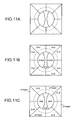
- Fig. 11A is a schematic diagram of the electrode pattern of the transparent electrode used for correcting the optical system wavefront aberration according to the third variant.
- the transparent electrode in the second variant corresponds to both the astigmatism and the comatic aberration, that is, it has the electrode pattern where the pattern shown in Fig. 3B and the pattern shown in Fig. 10A are combined.
- the present invention can be adapted for various wavefront aberrations that occur as the optical system wavefront aberration. Therefore, it is not necessary to interpret that the present invention is limited to the comatic aberration in the rotation direction as the optical system wavefront aberration.
- the optical recording medium reproducing device is designed so that an appropriate voltage is applied to the transparent electrode 28 provided in the liquid crystal panel 9 to correct the optical system wavefront aberration that occurs in the entire optical system in the optical pickup mechanism 39 including the objective lens 41.
- the value of the voltage applied to the electrode pattern of the transparent electrode 28 is adjusted before being shipped as products, and the information such as optimal voltage value is stored in the optical system wavefront aberration information storage unit 18, thereby performing the correction of the optical system wavefront aberration.
- Fig. 15A is a diagram of the electrode pattern of the transparent electrode used for correcting the medium wavefront aberration
- Fig. 15B is a diagram of the electrode pattern of the transparent electrode used for correcting the optical system wavefront aberration.
- the region surrounded by a dashed like indicates the region where the light flux used for the spot forming passes in using both a BD and a DVD.
- the same objective lens is used in the different optical recording mediums 14 in the first embodiment.
- the light flux used for the spot forming among the laser beams passing through the liquid crystal panel 9 is different in using the optical recording medium 14 due to the difference in NA values in the respective optical recording mediums 14.
- the focal distance between the objective lens 41 and the objective lens 42 is adjusted to correspond to the difference in the NA values so that, even when different optical recording mediums 14 are used, the light flux passing through the same region among the laser beams passing through the liquid crystal panel 9 is used for the spot forming.
- the first and the second embodiments according to the present invention and their variants are explained hereinabove, but the present invention is not limited to the above, and those skilled in the art can apply the present invention to various embodiments, variants, and applications.
- the first and the second embodiments and their variants have the structure where the optical system is optimized for a BD, but the structure may be optimized for a DVD, and the transparent electrode 28 may be used for correcting the optical system wavefront aberration that occurs in using a BD.
- the kinds of the optical recording medium 14 to be used is not limited to two kinds, and the optical recording medium reproducing device having an arbitrary natural number of kinds of mediums can be formed.
Landscapes
- Physics & Mathematics (AREA)
- Optics & Photonics (AREA)
- Chemical & Material Sciences (AREA)
- Crystallography & Structural Chemistry (AREA)
- Optical Head (AREA)
- Optical Recording Or Reproduction (AREA)
Applications Claiming Priority (2)
| Application Number | Priority Date | Filing Date | Title |
|---|---|---|---|
| JP2003356961A JP2005122828A (ja) | 2003-10-16 | 2003-10-16 | 光ピックアップ装置および光学記録媒体再生装置 |
| JP2003356961 | 2003-10-16 |
Publications (2)
| Publication Number | Publication Date |
|---|---|
| EP1524655A2 true EP1524655A2 (de) | 2005-04-20 |
| EP1524655A3 EP1524655A3 (de) | 2006-05-17 |
Family
ID=34373614
Family Applications (1)
| Application Number | Title | Priority Date | Filing Date |
|---|---|---|---|
| EP04024271A Withdrawn EP1524655A3 (de) | 2003-10-16 | 2004-10-12 | Optische Abtastvorrichtung und Wiedergabegerät für ein optisches Speichermedium |
Country Status (3)
| Country | Link |
|---|---|
| US (1) | US7428193B2 (de) |
| EP (1) | EP1524655A3 (de) |
| JP (1) | JP2005122828A (de) |
Families Citing this family (12)
| Publication number | Priority date | Publication date | Assignee | Title |
|---|---|---|---|---|
| JP2007122842A (ja) * | 2005-10-31 | 2007-05-17 | Toshiba Corp | 光ヘッド及び光ディスク装置 |
| US8045442B2 (en) | 2005-11-08 | 2011-10-25 | Nec Corporation | Optical information recording/ reproducing device and optical information recording/ reproducing method |
| JP4484814B2 (ja) * | 2005-12-26 | 2010-06-16 | 株式会社日立メディアエレクトロニクス | 収差補正装置及びそれを備える光ピックアップ |
| WO2007091488A1 (ja) * | 2006-02-08 | 2007-08-16 | Pioneer Corporation | 光ピックアップ及び光ピックアップ用プログラム |
| JP4732511B2 (ja) | 2006-03-29 | 2011-07-27 | パイオニア株式会社 | 光学式記録再生装置 |
| JP2008059681A (ja) * | 2006-08-31 | 2008-03-13 | Funai Electric Co Ltd | 光ピックアップ装置 |
| JP2008084444A (ja) * | 2006-09-27 | 2008-04-10 | Sanyo Electric Co Ltd | 光ピックアップ装置および光ディスク装置 |
| WO2008044403A1 (fr) * | 2006-10-06 | 2008-04-17 | Nec Corporation | Dispositif à tête optique, enregistreur/reproducteur d'informations optiques, procédé de génération de signal d'erreur |
| JP2009301648A (ja) * | 2008-06-13 | 2009-12-24 | Pioneer Electronic Corp | 収差補正装置及び光ピックアップ |
| JP2009301649A (ja) * | 2008-06-13 | 2009-12-24 | Pioneer Electronic Corp | 収差補正装置及び光ピックアップ |
| JP4489131B2 (ja) | 2008-07-31 | 2010-06-23 | 株式会社東芝 | 収差補正素子、光ヘッド及び光ディスク装置 |
| CN102063913B (zh) | 2009-11-12 | 2013-12-18 | 日立民用电子株式会社 | 变形镜致动器和光盘装置 |
Citations (5)
| Publication number | Priority date | Publication date | Assignee | Title |
|---|---|---|---|---|
| JPH11110802A (ja) * | 1997-10-03 | 1999-04-23 | Pioneer Electron Corp | 収差補正装置及び情報再生装置 |
| US6141304A (en) * | 1997-04-16 | 2000-10-31 | Pioneer Electronic Corporation | Optical pickup |
| US6151154A (en) * | 1998-03-12 | 2000-11-21 | Pioneer Electronic Corporation | Optical pickup, aberration correction unit and astigmatism measurement method |
| US20020191502A1 (en) * | 2001-06-13 | 2002-12-19 | Hideaki Hirai | Optical pickup unit and information recording and reproduction apparatus |
| WO2003049095A2 (en) * | 2001-12-07 | 2003-06-12 | Koninklijke Philips Electronics N.V. | Optical scanning device |
Family Cites Families (6)
| Publication number | Priority date | Publication date | Assignee | Title |
|---|---|---|---|---|
| JP3443226B2 (ja) * | 1995-08-31 | 2003-09-02 | パイオニア株式会社 | 光ピックアップ |
| JP3778316B2 (ja) * | 1997-05-22 | 2006-05-24 | パイオニア株式会社 | 光ピックアップ装置 |
| DE60043531D1 (de) * | 1999-09-02 | 2010-01-28 | Asahi Glass Co Ltd | Optischer kopf |
| JP3547000B2 (ja) * | 2000-05-30 | 2004-07-28 | シャープ株式会社 | 光ピックアップ装置 |
| JP3781273B2 (ja) * | 2001-02-07 | 2006-05-31 | パイオニア株式会社 | 収差補正素子及び収差補正ユニット |
| JP4256788B2 (ja) * | 2002-03-04 | 2009-04-22 | パナソニック株式会社 | 光ヘッド及びそれを用いた光記録再生装置 |
-
2003
- 2003-10-16 JP JP2003356961A patent/JP2005122828A/ja active Pending
-
2004
- 2004-10-12 US US10/960,926 patent/US7428193B2/en not_active Expired - Fee Related
- 2004-10-12 EP EP04024271A patent/EP1524655A3/de not_active Withdrawn
Patent Citations (5)
| Publication number | Priority date | Publication date | Assignee | Title |
|---|---|---|---|---|
| US6141304A (en) * | 1997-04-16 | 2000-10-31 | Pioneer Electronic Corporation | Optical pickup |
| JPH11110802A (ja) * | 1997-10-03 | 1999-04-23 | Pioneer Electron Corp | 収差補正装置及び情報再生装置 |
| US6151154A (en) * | 1998-03-12 | 2000-11-21 | Pioneer Electronic Corporation | Optical pickup, aberration correction unit and astigmatism measurement method |
| US20020191502A1 (en) * | 2001-06-13 | 2002-12-19 | Hideaki Hirai | Optical pickup unit and information recording and reproduction apparatus |
| WO2003049095A2 (en) * | 2001-12-07 | 2003-06-12 | Koninklijke Philips Electronics N.V. | Optical scanning device |
Non-Patent Citations (1)
| Title |
|---|
| PATENT ABSTRACTS OF JAPAN vol. 1999, no. 09, 30 July 1999 (1999-07-30) & JP 11 110802 A (PIONEER ELECTRON CORP), 23 April 1999 (1999-04-23) * |
Also Published As
| Publication number | Publication date |
|---|---|
| US20050083824A1 (en) | 2005-04-21 |
| EP1524655A3 (de) | 2006-05-17 |
| JP2005122828A (ja) | 2005-05-12 |
| US7428193B2 (en) | 2008-09-23 |
Similar Documents
| Publication | Publication Date | Title |
|---|---|---|
| JP3538520B2 (ja) | 収差補正用液晶パネル、光ピックアップ及び情報再生装置 | |
| US20050163015A1 (en) | Optical pickup and recording/reproducing apparatus | |
| JPH09106566A (ja) | 光ピックアップ | |
| US7428193B2 (en) | Optical pickup device and optical recording medium reproducing device | |
| KR100931278B1 (ko) | 광 헤드 및 광학 장치 | |
| JP2002237076A (ja) | 収差補正装置 | |
| US6859429B2 (en) | Aberration correcting unit, optical pickup apparatus, and recording/reproducing apparatus | |
| EP1560209B1 (de) | Optisches flüssigkristallelement und optische einrichtung | |
| JP3841993B2 (ja) | 収差補正光学素子とピックアップ装置及び情報再生装置並びに情報記録装置 | |
| JP2008181612A (ja) | 光ピックアップ | |
| US20070013984A1 (en) | Active compensation device, and compatible optical pickup and optical recording and/or reproducing apparatus employing the active compensation device | |
| JP4533178B2 (ja) | 光ピックアップ及びこれを用いた光情報処理装置 | |
| US7764587B2 (en) | Optical pickup apparatus | |
| US20070237053A1 (en) | Aberration correcting unit, optical pickup device, information reproducing apparatus, and aberration correcting program | |
| JP2000090479A (ja) | 液晶パネル、光ピックアップ及び情報再生装置 | |
| JP2002050068A (ja) | 光ピックアップ装置 | |
| JP2008059681A (ja) | 光ピックアップ装置 | |
| JP2000132854A (ja) | 光ディスク装置 | |
| JP3547626B2 (ja) | 光ピックアップ、情報再生装置及び情報記録装置 | |
| US20070047422A1 (en) | Compatible optical pickup and an optical recording and/or reproducing apparatus employing a compatible optical pickup | |
| JPWO2007026588A1 (ja) | 光ピックアップ装置及びホログラム記録再生システム | |
| WO2006121038A1 (ja) | 情報機器 | |
| JPH09161306A (ja) | 光ディスク装置 | |
| US20080101201A1 (en) | Optical Pickup Device | |
| JPS63257929A (ja) | 光学式情報記録再生装置 |
Legal Events
| Date | Code | Title | Description |
|---|---|---|---|
| PUAI | Public reference made under article 153(3) epc to a published international application that has entered the european phase |
Free format text: ORIGINAL CODE: 0009012 |
|
| AK | Designated contracting states |
Kind code of ref document: A2 Designated state(s): AT BE BG CH CY CZ DE DK EE ES FI FR GB GR HU IE IT LI LU MC NL PL PT RO SE SI SK TR |
|
| AX | Request for extension of the european patent |
Extension state: AL HR LT LV MK |
|
| PUAL | Search report despatched |
Free format text: ORIGINAL CODE: 0009013 |
|
| AK | Designated contracting states |
Kind code of ref document: A3 Designated state(s): AT BE BG CH CY CZ DE DK EE ES FI FR GB GR HU IE IT LI LU MC NL PL PT RO SE SI SK TR |
|
| AX | Request for extension of the european patent |
Extension state: AL HR LT LV MK |
|
| 17P | Request for examination filed |
Effective date: 20060623 |
|
| 17Q | First examination report despatched |
Effective date: 20060810 |
|
| AKX | Designation fees paid |
Designated state(s): DE FR GB |
|
| GRAP | Despatch of communication of intention to grant a patent |
Free format text: ORIGINAL CODE: EPIDOSNIGR1 |
|
| STAA | Information on the status of an ep patent application or granted ep patent |
Free format text: STATUS: THE APPLICATION IS DEEMED TO BE WITHDRAWN |
|
| 18D | Application deemed to be withdrawn |
Effective date: 20070927 |