EP1524498A1 - Photodetection device for rotary laser system - Google Patents
Photodetection device for rotary laser system Download PDFInfo
- Publication number
- EP1524498A1 EP1524498A1 EP04256081A EP04256081A EP1524498A1 EP 1524498 A1 EP1524498 A1 EP 1524498A1 EP 04256081 A EP04256081 A EP 04256081A EP 04256081 A EP04256081 A EP 04256081A EP 1524498 A1 EP1524498 A1 EP 1524498A1
- Authority
- EP
- European Patent Office
- Prior art keywords
- photodetection device
- laser system
- rotary laser
- photodetection
- photodetectors
- Prior art date
- Legal status (The legal status is an assumption and is not a legal conclusion. Google has not performed a legal analysis and makes no representation as to the accuracy of the status listed.)
- Withdrawn
Links
Images


Classifications
-
- G—PHYSICS
- G01—MEASURING; TESTING
- G01C—MEASURING DISTANCES, LEVELS OR BEARINGS; SURVEYING; NAVIGATION; GYROSCOPIC INSTRUMENTS; PHOTOGRAMMETRY OR VIDEOGRAMMETRY
- G01C15/00—Surveying instruments or accessories not provided for in groups G01C1/00 - G01C13/00
- G01C15/02—Means for marking measuring points
- G01C15/06—Surveyors' staffs; Movable markers
-
- G—PHYSICS
- G01—MEASURING; TESTING
- G01C—MEASURING DISTANCES, LEVELS OR BEARINGS; SURVEYING; NAVIGATION; GYROSCOPIC INSTRUMENTS; PHOTOGRAMMETRY OR VIDEOGRAMMETRY
- G01C15/00—Surveying instruments or accessories not provided for in groups G01C1/00 - G01C13/00
- G01C15/002—Active optical surveying means
- G01C15/004—Reference lines, planes or sectors
- G01C15/006—Detectors therefor
Definitions
- the present invention relates to a photodetection device for receiving a laser beam projected by rotary irradiation and for measuring an operating position according to photodetecting condition.
- a system which comprises a rotary laser system and a photodetection device installed at a measuring point for receiving a laser beam from the rotary laser system.
- the rotary laser system projects a laser beam each having a spot-like cross-section by rotary irradiation and forms a reference plane. For instance, by projecting a laser beam within a horizontal plane by rotary irradiation, a horizontal reference plane is formed. By projecting the laser beam within a vertical plane, a vertical reference plane is formed. By projecting the laser beam within a tilted plane, a tilted reference plane is formed.
- the photodetection device has a photodetector for receiving and detecting the laser beam. Based on the laser beam detected by the photodetector, a horizontal reference position, a vertical reference position, etc. are measured. Further, when the rotary laser system projects the laser beam in rotary irradiation, the photodetection device detects the laser beam. Based on the result of detection, a distance between the photodetection device and the rotary laser system is measured.
- the photodetection device comprises a photodetector with a predetermined length mounted at a predetermined position on a rod-like body.
- the relation between the photodetection device and the reference plane is detected according to a photodetecting position of the laser beam by the photodetector, and the photodetection device is moved to an adequate position.
- the photodetection device is erected for installation at a measuring point by an operator.
- the photodetector receives the laser beam when the operator moves the photodetection device as necessary up and down, for example.
- the photodetector must have a certain length.
- JP-A-2002-39755 proposes a measuring system, which can detect positional relation between the photodetector and the laser beam only by the photodetection device, which merely comprises a spot-like photodetector.
- a rotary laser system projects a plurality of tilted fan-shaped laser beams by rotary irradiation to facilitate the receiving of the laser beams by the photodetection device, and deviation of the laser beams from a reference position is detected according to time difference caused when the photodetector receives the plurality of fan-shaped laser beams.
- This makes it possible to perform communication between the photodetection device and the rotary laser system when communication data are superimposed on the laser beams. An amount of deviation and a direction of deviation are transmitted to the photodetection device, and a position of the photodetection device can be accurately adjusted.
- JP-A-2002-39755 is based on the assumption that the photodetection device is held at the vertical position.
- the system has to be constructed in such manner that a tilt sensor or the like should be provided on the photodetection device side, and that an operator must hold the photodetection device at the vertical position.
- the photodetection device must have complicated structure.
- a distance is measured by the photodetection device and the rotary laser system, a lower end of the photodetection device acts as a measuring point.
- the photodetection device is tilted, there has been such problem that the deviation between the lower end and the photodetection device may directly cause a measurement error.
- the present invention provides a photodetection device for a rotary laser system for projecting at least two fan-shaped beams tilted at a known angle with respect to a horizontal plane and having a known spreading angle, comprising at least three photodetectors arranged in a known relationship. Also, the present invention provides the photodetection device for the rotary laser system as described above, wherein at least one of the photodetectors is provided at a position deviated from a line connecting the photodetectors with each other.
- the present invention provides the photodetection device for the rotary laser system as described above, wherein at least two of the three or more photodetectors are provided on a plane facing to the rotary laser system, and at least one of the photodetectors is provided at a position deviated from the plane. Also, the present invention provides the photodetection device for the rotary laser system as described above, wherein the photodetection device comprises an arithmetic operation unit for calculating a distance between the rotary laser system and the photodetection device based on time difference in the receiving of the fan-shaped beams by the photodetectors.
- the present invention provides the photodetection device for the rotary laser system as described above, wherein the photodetection device comprises a tilt detecting device. Also, the present invention provides the photodetection device for the rotary laser system as described above, wherein there is provided an arithmetic operation unit for calculating a tilt angle and a twist angle of the photodetection device based on a distance between the rotary laser system and the photodetection device and based on time difference in the receiving of the fan-shaped beams by the photodetectors.
- the present invention provides the photodetection device for the rotary laser system as described above, wherein the distance between the rotary laser system and the photodetection device is compensated based on the tilt angle and the twist angle of the photodetection device.
- the present invention provides the photodetection device for the rotary laser system as described above, wherein the rotary laser system is installed at a known point, the photodetection device comprises a GPS measuring device and an arithmetic operation unit, the arithmetic operation unit calculates a distance between the rotary laser system and the photodetection device based on a result of measurement by the GPS measuring device, a tilt angle of the photodetection device is calculated based on the calculated distance and based on time difference of the receiving of the fan-shaped beams by the photodetectors, and the result of measurement by the GPS measuring device is compensated based on the tilt angle.
- the present invention provides a photodetection device for a rotary laser system for projecting at least two fan-shaped beams tilted at a known angle with respect to a horizontal plane and having a known spreading angle, comprising at least three photodetectors arranged in a known relationship.
- the distance between the rotary laser system and the photodetection device can be calculated according to photodetecting condition at three photodetectors.
- At least one of the photodetectors is provided at a position deviated from the plane.
- a tilt angle and a twist angle of the photodetection device can be detected from the photodetecting conditions of three or more photodetectors.
- the distance between the rotary laser system and the photodetection device is compensated based on the tilt angle and the twist angle of the photodetection device.
- the rotary laser system is installed at a known point
- the photodetection device comprises a GPS measuring device and an arithmetic operation unit
- the arithmetic operation unit calculates a distance between the rotary laser system and the photodetection device based on a result of measurement by the GPS measuring device
- a tilt angle of the photodetection device is calculated based on the calculated distance and based on time difference of the receiving of the fan-shaped beams by the photodetectors
- the result of measurement by the GPS measuring device is compensated based on the tilt angle.
- a rotary laser system 1 projects a plurality of fan-shaped laser beams by rotary irradiation, and a photodetection device 2 comprises at least two photodetectors for receiving the fan-shaped laser beams.
- a tripod 5 is installed at a point approximately aligned with an approximately known point X, and the rotary laser system 1 is mounted on the tripod 5.
- the rotary laser system 1 comprises a main unit 6 and a rotating unit 7 rotatably mounted on the main unit 6. From the rotating unit 7, a laser beam 3 is projected by rotary irradiation at a constant rate.
- the photodetection device 2 is held by support means as required.
- Fig. 1 shows a condition in outdoor operation, and the photodetection device 2 is mounted on a rod 8, which can be hand-carried by an operator.
- the laser beam 3 comprises a plurality of fan-shaped beams.
- the laser beam 3 comprises vertical fan-shaped beams 3a and 3b and a fan-shaped beam 3c tilted with respect to the fan-shaped beams 3a and 3b at a known angle ⁇ on a diagonal line to form N-shaped configuration.
- the fan-shaped beams 3a and 3b are projected in directions of ⁇ ⁇ with a spreading angle of ⁇ respectively (See Fig. 6).
- the fan-shaped beams 3a and 3b are not necessarily vertical beams. It is merely required that the fan-shaped beams 3a and 3b are running in parallel to each other and are crossing the horizontal plane.
- the rotary laser system 1 comprises a casing 10 and a laser projector 12 with a projection optical axis 11 (to be described later).
- the laser projector 12 is tiltably accommodated in the casing 10.
- a recessed portion 13 in form of a truncated cone is provided at a center on an upper surface of the casing 10, and the laser projector 12 is penetrating though a center of the recessed portion 13 in an up-to-bottom direction.
- the laser projector 12 is supported on the recessed portion 13 via a spherical seat 14 so that the laser projector 12 can be tilted.
- the rotating unit 7 On an upper portion of the laser projector 12, the rotating unit 7 is rotatably mounted, and a pentagonal prism 15 is provided on the rotating unit 7.
- a scanning gear 16 is mounted on the rotating unit 7.
- a scanning motor 18 with a driving gear 17 is provided on the laser projector 12.
- the rotating unit 7 is rotated and driven by the scanning motor 18 via the driving gear 17 and the scanning gear 16.
- the tilting mechanism 19 comprises a motor for tilting 21, a screw for tilting 22 with a center of rotation in parallel to the laser projector 12, and a tilting nut 23 engaged with the screw for tilting 22.
- the laser projector 12 has two tilting arms 24 (only one of the tilting arms 24 is shown) extending in two directions perpendicular to the projection optical axis 11, and the tilting arms 24 cross each other perpendicularly.
- a pin with a circular cross-section is protruded, and the tilting arm 24 is engaged with the tilting mechanism 19 via the pin.
- the motor for tilting 21 can rotate the screw for tilting 22 via a driving gear 25 and a gear for tilting 26.
- the tilting nut 23 is moved in an up-to-bottom direction.
- the tilting arm 24 is tilted, and the laser projector 12 is tilted.
- Another set of the tilting mechanism not shown in the figure tilts the laser projector 12 in a direction running perpendicularly to the tilting direction of the tilting mechanism 19 by the same mechanism as the tilting mechanism 19.
- a tilt angle in an arbitrary direction of the laser projector 12 can be detected based on the fixed tilt sensors 27 and 28.
- the laser projector 12 is tilted via the two tilting arms 24 by the two sets of the tilting mechanisms 19, and it can be so controlled that the laser projector 12 is always directed in a vertical direction.
- the laser projector 12 can be tilted at any angle as desired.
- a laser beam emitting unit 31 and a collimator lens 32 arranged on the projection optical axis 11 make up together a projection optical system 33, and the projection optical system 33 is accommodated in the laser projector 12.
- the rotating unit 7 has a prism holder 34.
- the prism holder 34 holds the pentagonal prism 15 and a diffraction grating (BOE) 35 provided on a lower side of the pentagonal prism 15.
- BOE diffraction grating
- the laser beam 3 emitted from the laser beam emitting unit 31 is turned to a parallel luminous flux by the collimator lens 32 and enters the diffraction grating 35.
- the incident laser beam 3 is divided to form three fan-shaped beams 3a, 3b and 3c by the diffraction grating 35.
- the fan-shaped beams 3a, 3b and 3c are deflected in a horizontal direction by the pentagonal prism 15, and these beams are projected through a projection window 36 of the prism holder 34.
- the diffraction grating 35 may be arranged at a position where the laser beams 3 pass through after being deflected by the pentagonal prism 15.
- reference numeral 37 denotes an encoder for detecting a rotation angle of the rotating unit 7, and 38 represents a transparent cover in cylindrical shape.
- Light emitting condition of the laser beam emitting unit 31 is controlled by a light emission control unit 39. For instance, by such a method as to modulate the laser beam 3, communication data can be superimposed on the laser beam 3. Optical communication can be performed to send data such as position information of the rotary laser system 1 in a direction of rotary irradiation toward the photodetection device 2.
- a separate radio communication equipment may be provided as communication means, and the data may be transmitted to the photodetection device 2 via radio communication.
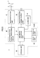
- the photodetection deice 2 comprises photodetection unit 41 for detecting the fan-shaped beams 3a, 3b and 3c, a display unit 42, an index display unit 43, an alarm unit 44 such as a buzzer and an input unit 45 such as input keys.
- the photodetection unit 41 comprises a plurality of photodetectors 41a and 41b having light emitting elements such as laser diodes arranged at two positions, for example, above and under respectively. A distance D between the photodetector 41a and the photodetector 41b is set to a known value.
- the photodetection device 2 incorporates a storage unit 46, an arithmetic operation unit 47, a photodetection signal processing circuit 48, and a photodetection signal output unit 49.
- the index display unit 43 comprises an index having a central line and upper and lower triangular marks. When a scanning position of the laser beams 3 is at the center of the horizontal line, it is shown by the center line. When the scanning position of the laser beams 3 is above or under the center of the horizontal line, it is shown by the triangular marks.
- a photodetection signal is inputted from the photodetection unit 41 to the photodetection signal processing circuit 48. Then, it is detected whether the light has been received or not.
- the signal is processed by the required processing such as A/D conversion.
- communication data superimposed on the fan-shaped beams 3a, 3b or 3c is extracted and analyzed, and the result is inputted to the arithmetic operation unit 47. As described later, based on the signal from the photodetection signal processing unit 48, the arithmetic operation unit 47 calculates the elevation angle ⁇ .
- a distance L between the rotary laser system 1 and the photodetection device 2 and tilting of the rod 8 is calculated.
- the arithmetic operation unit 47 the result of calculation is inputted to the storage unit 46 or it is displayed on the display unit 42. Also, the result of calculation is transmitted to the rotary laser system 1 by the photodetection signal output unit 49 via optical communication.
- Position information such as the position of the known point X may be inputted to the storage unit 46 in advance by the input unit 45.
- a radio receiver is provided on the photodetection device 2.
- the photodetection signal output unit 49 outputs the result obtained from the calculation by the arithmetic operation unit 47.
- the output from the photodetection signal output unit 49 is used as a signal to drive the index display unit 43.
- the rotary laser system 1 is installed at the known point X via the tripod 5. Based on the result of detection by the fixed tilt sensors 27 and 28, the tilting mechanisms 19 are driven so that the laser projector 12 is adjusted to the vertical direction.
- the rod 8 is installed at a target position.
- the photodetection device 2 is mounted at a predetermined height on the rod 8, i.e. at a known height from the ground surface.
- a distance D between the photodetector 41a and the photodetector 41b is inputted to the photodetection device 2 in advance by the input unit 45.
- the distance D is stored in the storage unit 46 via the arithmetic operation unit 47.
- the height of the photodetection device 2 i.e. differences of height of the photodetectors 41a and 41b with respect to a reference plane, the distance L between the rotary laser system 1 and the photodetection device 2, and elevation angles ⁇ 1 and ⁇ 2 to the photodetectors 41a and 41b are calculated based on the photodetecting condition of the photodetection signals from the photodetectors 41a and 41b and the distance D.
- the elevation angles ⁇ 1 and ⁇ 2 are calculated by the arithmetic operation unit 47 according to the photodetection signals issued when the fan-shaped beams 3a, 3b and 3c are received by the photodetectors 41a and 41b respectively.
- the alarm unit 44 sounds buzzer, etc., and warns the operator.
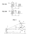
- Fig. 6 shows the relation between the photodetector 41 and the laser beams 3.
- the height H shows a height of a reference plane, i.e. a center height of the laser beam 3, namely a horizontal line.
- the laser beam 3 When the laser beam 3 is projected by rotary irradiation, the laser beam 3 runs across the photodetector 41a of the photodetection unit 41, for instance. Because the laser beam 3 comprises the fan-shaped beams 3a, 3b and 3c, light can be received even when the photodetector 41a is a spot-like photodetection element. There is no need to perform accurate positioning for the photodetection device 2.
- each of the fan-shaped beams 3a, 3b and 3c passes through the photodetector 41a. From the photodetector 41a, three photodetection signals 51a, 51b and 51c corresponding to the fan-shaped beams 3a, 3b and 3c respectively are issued.
- the rotating unit 7 is driven by rotation at a constant speed.
- T represents a period of one turn of the laser beam 3.
- time intervals of the photodetection signals 51a, 51c and 51b are different from each other (Fig. 10 (B)).
- Fig. 7 if it is assumed that the photodetector 41a is relatively shifted from the right to the left in the figure (the laser beam 3 is shifted from the left to the right in the figure), the time interval "t" between the photodetection signals 51a and 51c is shorter, and the time interval "t" between the photodetection signals 51c and 51b is longer.
- Fig. 6 shows similar figures regardless of the distance between the photodetection device 2 and the rotating unit 7.
- a passing position in the figure turned to dimensionless can be calculated. Therefore, regarding the photodetector 41a, the elevation angle ⁇ 1 up to the point B with the rotating unit 7 as the center can be calculated by the following equation (1).
- ⁇ 1 ⁇ (1 - 2t1/t0) tan ⁇
- the elevation angle ⁇ 2 of the photodetector 41b can be calculated by the following equation (2).
- ⁇ 2 ⁇ (1 - 2t2/t0) tan ⁇
- the distance L between the rotary laser system 1 and the photodetection device 2 can be calculated by the following equations.
- the above described distance L is determined by assuming that the rod 8 is at the vertical position.
- the rod 8 When the rod 8 is held by an operator, the rod 8 may be tilted.
- the rod 8 When the rod 8 is tilted toward a left or right direction facing to the rotary laser system 1, there is a time difference when the fan-shaped beams 3a and 3b in the vertical direction are received by the photodetectors 41a and 41b.
- the tilting can be compensated based on the time difference.
- the tilting of the rod 8 is not reflected in the elevation angle as shown in Fig. 12, and an error may occur. If a tilt detecting device is provided on the photodetection device 2 and the rod 8 is held in the vertical direction, the distance can be calculated without an error. Therefore, the distance between the rotary laser system 1 and the photodetection device 2 can be measured without the need of providing a distance-measuring device on the rotary laser system 1.
- Fig. 13 shows the photodetection device 2 when there are provided three photodetectors 41.
- a photodetector 41c is provided between the photodetectors 41a and 41b.
- a distance between the photodetector 41c and the photodetector 41a is A, and the photodetector 41c is arranged at a position recessed by a distance B from a line connecting the photodetector 41a with the photodetector 41b.
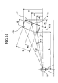
- Fig. 14 shows a case where the rod 8 is tilted at an angle of ⁇ 1 in the front-to-back direction facing to the rotary laser system 1.
- the elevation angles ⁇ 1, ⁇ 2 and ⁇ 3 can be obtained with respect to the photodetectors 41a, 41b and 41c respectively as described above.
- Fig. 15 shows a case where the rod 8 is tilted at an angle of ⁇ 1 in a front-to-back direction facing to the rotary laser system 1 and where the rod 8 is further twisted at an angle of ⁇ 2 around the axis.
- elevation angles ⁇ 1, ⁇ 2 and ⁇ 3 can be obtained with respect to the photodetectors 41a, 41b and 41c respectively.
- the photodetector 41c is deviated from a vertical plane including the photodetectors 41a and 41b. Because the fan-shaped beams 3a and 3b are spread in a vertical direction, light receiving time of the photodetector 41c is deviated by an amount of "t" with respect to the photodetectors 41a and 41b as shown in Fig. 16.
- ⁇ 2 ⁇ t/T (See Fig. 10. T represents a period of rotation of the laser beam.)
- tan ( ⁇ ) B sin ( ⁇ 2)/(L + A sin ( ⁇ 1) + B cos ( ⁇ 1) ⁇ cos ( ⁇ 2))
- ⁇ tan (2 ⁇ t/T) B sin ( ⁇ 2)/(L + A sin ( ⁇ 1) + B cos ( ⁇ 1) ⁇ cos ( ⁇ 2))
- the configuration may be not be N-shaped. It will suffice if at least one of the fan-shaped beams is tilted and a tilt angle and the like relating to the configuration are known.
- Fig. 13 (B) - Fig. 13 (D) show such arrangement that one of the photodetectors, i.e. the photodetector 41c, is deviated from a plane, in which the other photodetectors 41a, 41b, 41d and 41e are included. All of the photodetectors 41 may be within the same plane. With respect to the number and the arrangement of the photodetectors 41, it will suffice if there are at least three photodetectors 41 and the three photodetectors 41 are not on the same line.
- the rotary laser system 1 may not comprise a distance-measuring unit and the photodetection device 2 may not comprise a tilt sensor, it is possible to measure the distance between the rotary laser system 1 and the photodetection device 2 with high accuracy.
- a GPS measuring device may be provided on the photodetection device 2.
- the GPS measuring device is provided at an upper end of the rod 8, and a distance between the GPS measuring device and the lower end of the rod 8 is already known.
- an absolute plane position of the GPS measuring device can be measured.
- a distance between the photodetection device 2 and the rotary laser system 1 can be calculated from the position measured by the GPS measuring device and from the position of a known point where the rotary laser system 1 is installed.
- tilting of the rod 8 can be measured by the photodetection device 2. Because the distance between the lower end of the rod 8 and the GPS measuring device is already known, an error caused by the tilting of the rod 8 can be compensated, and the distance measurement can be achieved with high accuracy.
Landscapes
- Physics & Mathematics (AREA)
- Engineering & Computer Science (AREA)
- General Physics & Mathematics (AREA)
- Radar, Positioning & Navigation (AREA)
- Remote Sensing (AREA)
- Length Measuring Devices By Optical Means (AREA)
- Optical Radar Systems And Details Thereof (AREA)
Applications Claiming Priority (2)
| Application Number | Priority Date | Filing Date | Title |
|---|---|---|---|
| JP2003353826 | 2003-10-14 | ||
| JP2003353826A JP4282432B2 (ja) | 2003-10-14 | 2003-10-14 | 回転レーザ装置の受光装置 |
Publications (1)
| Publication Number | Publication Date |
|---|---|
| EP1524498A1 true EP1524498A1 (en) | 2005-04-20 |
Family
ID=34373548
Family Applications (1)
| Application Number | Title | Priority Date | Filing Date |
|---|---|---|---|
| EP04256081A Withdrawn EP1524498A1 (en) | 2003-10-14 | 2004-10-01 | Photodetection device for rotary laser system |
Country Status (3)
| Country | Link |
|---|---|
| US (1) | US7115852B2 (ja) |
| EP (1) | EP1524498A1 (ja) |
| JP (1) | JP4282432B2 (ja) |
Cited By (8)
| Publication number | Priority date | Publication date | Assignee | Title |
|---|---|---|---|---|
| US7196302B2 (en) | 2004-03-23 | 2007-03-27 | Kabushiki Kaisha Topcon | Laser measuring method and laser measuring system having fan-shaped tilted laser beams and three known points of photodetection system |
| WO2007089429A2 (en) * | 2006-02-01 | 2007-08-09 | Trimble Navigation Limited | Position indicating and guidance control system and method thereof |
| EP1912041A1 (en) * | 2006-10-09 | 2008-04-16 | MOBA - Mobile Automation AG | Apparatus and method for determining an elevation of working tools |
| WO2008104401A1 (en) * | 2007-03-01 | 2008-09-04 | Prüftechnik Dieter Busch AG | Method of determining the flatness of a foundation to which a building structure, machinery or equipment is to be mounted |
| EP3029418A3 (en) * | 2014-11-12 | 2016-10-05 | Kabushiki Kaisha Topcon | Tilt detecting system and tilt detecting method |
| EP2708968A3 (en) * | 2012-09-12 | 2017-03-15 | Kabushiki Kaisha Topcon | Construction machine control method and construction machine control system |
| EP3839428A1 (de) * | 2019-12-16 | 2021-06-23 | Hilti Aktiengesellschaft | Verfahren zum bestimmen eines abstandes zwischen einem lasersystem und einer projektionsfläche |
| CN113483735A (zh) * | 2021-06-10 | 2021-10-08 | 中铁大桥局上海工程有限公司 | 一种装配式桥梁预制立柱模板垂直度检测装置 |
Families Citing this family (12)
| Publication number | Priority date | Publication date | Assignee | Title |
|---|---|---|---|---|
| JP4274129B2 (ja) * | 2005-01-31 | 2009-06-03 | セイコーエプソン株式会社 | プロジェクタ |
| DE112007001624B4 (de) * | 2006-07-12 | 2019-07-04 | Trimble Navigation Ltd. | Handgehaltener Laserlichtdetektor mit Höhenkorrektur, unter Verwendung eines GPS-Empfängers zum Bereitstellen von zweidimensionalen Positionsdaten |
| WO2009154625A1 (en) | 2008-06-19 | 2009-12-23 | Trimble Navigation Limited | Positioning device and method for detecting a laser beam |
| JP5280258B2 (ja) * | 2009-03-16 | 2013-09-04 | 株式会社トプコン | 測量システム |
| JP5456549B2 (ja) | 2010-04-15 | 2014-04-02 | 株式会社トプコン | 測量システム及び測量システムに於けるレーザ基準面平滑化方法 |
| JP2011242176A (ja) * | 2010-05-14 | 2011-12-01 | Bridgestone Corp | 帯状部材の形状測定方法とその装置及び変位センサー |
| JP6670127B2 (ja) | 2016-02-24 | 2020-03-18 | 株式会社トプコン | 建設機械の制御システム |
| JP6666406B2 (ja) * | 2018-09-27 | 2020-03-13 | 株式会社トプコン | 写真測量システム |
| JP7191736B2 (ja) * | 2019-03-11 | 2022-12-19 | 株式会社トプコン | アスファルトフィニッシャ及びスクリード制御方法 |
| JP7178311B2 (ja) * | 2019-03-29 | 2022-11-25 | 株式会社トプコン | ガイド光照射装置 |
| EP4256273A1 (en) | 2020-12-01 | 2023-10-11 | Milwaukee Electric Tool Corporation | Laser level interface and control |
| EP4012334B1 (en) * | 2020-12-11 | 2023-10-18 | Leica Geosystems AG | Surveying pole and secondary sensor unit having toroidal form |
Citations (6)
| Publication number | Priority date | Publication date | Assignee | Title |
|---|---|---|---|---|
| US4441809A (en) * | 1979-10-16 | 1984-04-10 | Dudley James R | Method and apparatus for determining position |
| US5767960A (en) * | 1996-06-14 | 1998-06-16 | Ascension Technology Corporation | Optical 6D measurement system with three fan-shaped beams rotating around one axis |
| EP1174682A2 (en) * | 2000-07-19 | 2002-01-23 | Kabushiki Kaisha TOPCON | Position determination system |
| US20030090652A1 (en) * | 2000-03-10 | 2003-05-15 | Detweiler Philip J. | Versatile transmitter and receiver for position measurement |
| US20030136901A1 (en) * | 2002-01-21 | 2003-07-24 | Fumio Ohtomo | Position determining apparatus and rotary laser apparatus used with the same |
| US20030174305A1 (en) * | 2000-08-01 | 2003-09-18 | Michael Kasper | Measuring device and measuring method for determining distance and/or position |
Family Cites Families (8)
| Publication number | Priority date | Publication date | Assignee | Title |
|---|---|---|---|---|
| JP4712212B2 (ja) | 2001-03-28 | 2011-06-29 | 株式会社トプコン | レーザ照準装置 |
| JP4614565B2 (ja) | 2001-03-28 | 2011-01-19 | 株式会社トプコン | レーザ光線照射装置 |
| JP4653898B2 (ja) | 2001-03-28 | 2011-03-16 | 株式会社トプコン | 傾斜検出装置 |
| JP2004212058A (ja) | 2002-12-26 | 2004-07-29 | Topcon Corp | 作業位置測定装置 |
| JP4281907B2 (ja) | 2003-10-14 | 2009-06-17 | 株式会社トプコン | レーザ照射装置 |
| JP4290520B2 (ja) | 2003-10-14 | 2009-07-08 | 株式会社トプコン | レーザ照射装置 |
| JP4328653B2 (ja) | 2004-03-23 | 2009-09-09 | 株式会社トプコン | レーザ測定システム |
| JP4328654B2 (ja) | 2004-03-23 | 2009-09-09 | 株式会社トプコン | レーザ測定方法及びレーザ測定システム |
-
2003
- 2003-10-14 JP JP2003353826A patent/JP4282432B2/ja not_active Expired - Fee Related
-
2004
- 2004-09-30 US US10/955,589 patent/US7115852B2/en active Active
- 2004-10-01 EP EP04256081A patent/EP1524498A1/en not_active Withdrawn
Patent Citations (6)
| Publication number | Priority date | Publication date | Assignee | Title |
|---|---|---|---|---|
| US4441809A (en) * | 1979-10-16 | 1984-04-10 | Dudley James R | Method and apparatus for determining position |
| US5767960A (en) * | 1996-06-14 | 1998-06-16 | Ascension Technology Corporation | Optical 6D measurement system with three fan-shaped beams rotating around one axis |
| US20030090652A1 (en) * | 2000-03-10 | 2003-05-15 | Detweiler Philip J. | Versatile transmitter and receiver for position measurement |
| EP1174682A2 (en) * | 2000-07-19 | 2002-01-23 | Kabushiki Kaisha TOPCON | Position determination system |
| US20030174305A1 (en) * | 2000-08-01 | 2003-09-18 | Michael Kasper | Measuring device and measuring method for determining distance and/or position |
| US20030136901A1 (en) * | 2002-01-21 | 2003-07-24 | Fumio Ohtomo | Position determining apparatus and rotary laser apparatus used with the same |
Cited By (15)
| Publication number | Priority date | Publication date | Assignee | Title |
|---|---|---|---|---|
| US7196302B2 (en) | 2004-03-23 | 2007-03-27 | Kabushiki Kaisha Topcon | Laser measuring method and laser measuring system having fan-shaped tilted laser beams and three known points of photodetection system |
| US7714993B2 (en) | 2006-02-01 | 2010-05-11 | Trimble Navigation Limited | Position indicating and guidance system and method thereof |
| WO2007089429A2 (en) * | 2006-02-01 | 2007-08-09 | Trimble Navigation Limited | Position indicating and guidance control system and method thereof |
| WO2007089429A3 (en) * | 2006-02-01 | 2007-12-13 | Trimble Navigation Ltd | Position indicating and guidance control system and method thereof |
| DE112007000285B4 (de) * | 2006-02-01 | 2014-10-23 | Trimble Navigation Ltd. | Position anzeigendes Führungssteuersystem und Verfahren für dasselbe |
| CN101410573B (zh) * | 2006-02-01 | 2012-09-26 | 天宝导航有限公司 | 位置指示与导向控制系统及其方法 |
| EP1912041A1 (en) * | 2006-10-09 | 2008-04-16 | MOBA - Mobile Automation AG | Apparatus and method for determining an elevation of working tools |
| WO2008043517A1 (en) * | 2006-10-09 | 2008-04-17 | Moba-Mobile Automation Ag | Apparatus and method for determining an elevation of working tools |
| WO2008104401A1 (en) * | 2007-03-01 | 2008-09-04 | Prüftechnik Dieter Busch AG | Method of determining the flatness of a foundation to which a building structure, machinery or equipment is to be mounted |
| EP2708968A3 (en) * | 2012-09-12 | 2017-03-15 | Kabushiki Kaisha Topcon | Construction machine control method and construction machine control system |
| EP3029418A3 (en) * | 2014-11-12 | 2016-10-05 | Kabushiki Kaisha Topcon | Tilt detecting system and tilt detecting method |
| US9733082B2 (en) | 2014-11-12 | 2017-08-15 | Kabushiki Kaisha Topcon | Tilt detecting system and tilt detecting method |
| EP3839428A1 (de) * | 2019-12-16 | 2021-06-23 | Hilti Aktiengesellschaft | Verfahren zum bestimmen eines abstandes zwischen einem lasersystem und einer projektionsfläche |
| CN113483735A (zh) * | 2021-06-10 | 2021-10-08 | 中铁大桥局上海工程有限公司 | 一种装配式桥梁预制立柱模板垂直度检测装置 |
| CN113483735B (zh) * | 2021-06-10 | 2022-11-29 | 中铁大桥局上海工程有限公司 | 一种装配式桥梁预制立柱模板垂直度检测装置 |
Also Published As
| Publication number | Publication date |
|---|---|
| JP4282432B2 (ja) | 2009-06-24 |
| US7115852B2 (en) | 2006-10-03 |
| US20050077454A1 (en) | 2005-04-14 |
| JP2005121388A (ja) | 2005-05-12 |
Similar Documents
| Publication | Publication Date | Title |
|---|---|---|
| US7196302B2 (en) | Laser measuring method and laser measuring system having fan-shaped tilted laser beams and three known points of photodetection system | |
| EP1524498A1 (en) | Photodetection device for rotary laser system | |
| US10823558B2 (en) | Surveying instrument | |
| EP1524497B1 (en) | Method and system for measuring height or relative axial position | |
| EP1434029B1 (en) | Position measuring system comprising a rotary laser | |
| JP4416925B2 (ja) | 位置測定設定システム及びそれに使用する受光センサ装置 | |
| US7081606B2 (en) | Position measuring system | |
| JP3582918B2 (ja) | レーザ測量機 | |
| EP2103902B1 (en) | Surveying Device and Surveying System | |
| EP1211484B1 (en) | Deviation detection device, rotary laser apparatus with the same, and position determining system with deviation detecting/correcting device | |
| JP7163085B2 (ja) | 測量方法、測量装置およびプログラム | |
| US20020060788A1 (en) | Position determining system | |
| US11004250B2 (en) | Point cloud data display system | |
| US7633609B2 (en) | Measuring system | |
| EP3457081B1 (en) | Surveying system | |
| US11500096B2 (en) | Surveying instrument | |
| JP4328653B2 (ja) | レーザ測定システム | |
| JP2019015602A (ja) | 測量システム | |
| WO2024071287A1 (ja) | ツイストリングポリゴンミラー、送光器、および測量システム | |
| JP2023000908A (ja) | 測量装置、光軸変換ユニット、測量方法及び測量プログラム | |
| JP2689266B2 (ja) | 三次元位置測量装置 | |
| JP2024050349A (ja) | 送光器および測量システム |
Legal Events
| Date | Code | Title | Description |
|---|---|---|---|
| PUAI | Public reference made under article 153(3) epc to a published international application that has entered the european phase |
Free format text: ORIGINAL CODE: 0009012 |
|
| AK | Designated contracting states |
Kind code of ref document: A1 Designated state(s): AT BE BG CH CY CZ DE DK EE ES FI FR GB GR HU IE IT LI LU MC NL PL PT RO SE SI SK TR |
|
| AX | Request for extension of the european patent |
Extension state: AL HR LT LV MK |
|
| 17P | Request for examination filed |
Effective date: 20050802 |
|
| AKX | Designation fees paid |
Designated state(s): CH DE LI SE |
|
| 17Q | First examination report despatched |
Effective date: 20141124 |
|
| STAA | Information on the status of an ep patent application or granted ep patent |
Free format text: STATUS: THE APPLICATION IS DEEMED TO BE WITHDRAWN |
|
| 18D | Application deemed to be withdrawn |
Effective date: 20160625 |