EP1524449B1 - A control system and method for the running clearance of a disc brake. - Google Patents
A control system and method for the running clearance of a disc brake. Download PDFInfo
- Publication number
- EP1524449B1 EP1524449B1 EP04256261A EP04256261A EP1524449B1 EP 1524449 B1 EP1524449 B1 EP 1524449B1 EP 04256261 A EP04256261 A EP 04256261A EP 04256261 A EP04256261 A EP 04256261A EP 1524449 B1 EP1524449 B1 EP 1524449B1
- Authority
- EP
- European Patent Office
- Prior art keywords
- brake
- motor
- displacement
- friction lining
- rotor
- Prior art date
- Legal status (The legal status is an assumption and is not a legal conclusion. Google has not performed a legal analysis and makes no representation as to the accuracy of the status listed.)
- Expired - Lifetime
Links
- 238000000034 method Methods 0.000 title claims description 16
- 238000006073 displacement reaction Methods 0.000 claims abstract description 14
- 230000007246 mechanism Effects 0.000 claims abstract description 14
- 238000012544 monitoring process Methods 0.000 claims description 4
- 230000011664 signaling Effects 0.000 claims 2
- 238000006243 chemical reaction Methods 0.000 description 3
- 230000000694 effects Effects 0.000 description 2
- 239000000463 material Substances 0.000 description 2
- 230000008901 benefit Effects 0.000 description 1
- 230000008859 change Effects 0.000 description 1
- 230000008602 contraction Effects 0.000 description 1
- 238000010586 diagram Methods 0.000 description 1
- 239000002783 friction material Substances 0.000 description 1
- 238000009434 installation Methods 0.000 description 1
- 238000005259 measurement Methods 0.000 description 1
- 230000003278 mimic effect Effects 0.000 description 1
- 238000012986 modification Methods 0.000 description 1
- 230000004048 modification Effects 0.000 description 1
- 230000009467 reduction Effects 0.000 description 1
- 230000004044 response Effects 0.000 description 1
Images


Classifications
-
- F—MECHANICAL ENGINEERING; LIGHTING; HEATING; WEAPONS; BLASTING
- F16—ENGINEERING ELEMENTS AND UNITS; GENERAL MEASURES FOR PRODUCING AND MAINTAINING EFFECTIVE FUNCTIONING OF MACHINES OR INSTALLATIONS; THERMAL INSULATION IN GENERAL
- F16D—COUPLINGS FOR TRANSMITTING ROTATION; CLUTCHES; BRAKES
- F16D65/00—Parts or details
- F16D65/14—Actuating mechanisms for brakes; Means for initiating operation at a predetermined position
- F16D65/16—Actuating mechanisms for brakes; Means for initiating operation at a predetermined position arranged in or on the brake
- F16D65/18—Actuating mechanisms for brakes; Means for initiating operation at a predetermined position arranged in or on the brake adapted for drawing members together, e.g. for disc brakes
-
- F—MECHANICAL ENGINEERING; LIGHTING; HEATING; WEAPONS; BLASTING
- F16—ENGINEERING ELEMENTS AND UNITS; GENERAL MEASURES FOR PRODUCING AND MAINTAINING EFFECTIVE FUNCTIONING OF MACHINES OR INSTALLATIONS; THERMAL INSULATION IN GENERAL
- F16D—COUPLINGS FOR TRANSMITTING ROTATION; CLUTCHES; BRAKES
- F16D65/00—Parts or details
- F16D65/38—Slack adjusters
- F16D2065/386—Slack adjusters driven electrically
-
- F—MECHANICAL ENGINEERING; LIGHTING; HEATING; WEAPONS; BLASTING
- F16—ENGINEERING ELEMENTS AND UNITS; GENERAL MEASURES FOR PRODUCING AND MAINTAINING EFFECTIVE FUNCTIONING OF MACHINES OR INSTALLATIONS; THERMAL INSULATION IN GENERAL
- F16D—COUPLINGS FOR TRANSMITTING ROTATION; CLUTCHES; BRAKES
- F16D66/00—Arrangements for monitoring working conditions, e.g. wear, temperature
- F16D2066/003—Position, angle or speed
-
- F—MECHANICAL ENGINEERING; LIGHTING; HEATING; WEAPONS; BLASTING
- F16—ENGINEERING ELEMENTS AND UNITS; GENERAL MEASURES FOR PRODUCING AND MAINTAINING EFFECTIVE FUNCTIONING OF MACHINES OR INSTALLATIONS; THERMAL INSULATION IN GENERAL
- F16D—COUPLINGS FOR TRANSMITTING ROTATION; CLUTCHES; BRAKES
- F16D66/00—Arrangements for monitoring working conditions, e.g. wear, temperature
- F16D2066/005—Force, torque, stress or strain
-
- F—MECHANICAL ENGINEERING; LIGHTING; HEATING; WEAPONS; BLASTING
- F16—ENGINEERING ELEMENTS AND UNITS; GENERAL MEASURES FOR PRODUCING AND MAINTAINING EFFECTIVE FUNCTIONING OF MACHINES OR INSTALLATIONS; THERMAL INSULATION IN GENERAL
- F16D—COUPLINGS FOR TRANSMITTING ROTATION; CLUTCHES; BRAKES
- F16D66/00—Arrangements for monitoring working conditions, e.g. wear, temperature
- F16D2066/006—Arrangements for monitoring working conditions, e.g. wear, temperature without direct measurement of the quantity monitored, e.g. wear or temperature calculated form force and duration of braking
-
- F—MECHANICAL ENGINEERING; LIGHTING; HEATING; WEAPONS; BLASTING
- F16—ENGINEERING ELEMENTS AND UNITS; GENERAL MEASURES FOR PRODUCING AND MAINTAINING EFFECTIVE FUNCTIONING OF MACHINES OR INSTALLATIONS; THERMAL INSULATION IN GENERAL
- F16D—COUPLINGS FOR TRANSMITTING ROTATION; CLUTCHES; BRAKES
- F16D2121/00—Type of actuator operation force
- F16D2121/02—Fluid pressure
Definitions
- the present invention is concerned with a control system and control method for a disc brake, in particular an adjuster mechanism of a disc brake.
- the rotation has the effect of moving the backstop or datum position for the return of the friction lining, thus progressively advancing the lining towards the brake rotor as the friction lining wears.
- the increased load in the system causes the clutch to slip, preventing further unwanted adjustment and/or overloading of the adjuster.
- Such mechanical automatic adjusters are well known in the art.
- a brake of the kind envisaged by the present invention it is important to reduce weight, power consumption (whether electrical or pneumatic) and material costs.
- a conventional brake having an automatic adjuster of the mechanical kind or even an electric adjuster that mimics the mechanical operation, the strength of the mechanisms associated with the adjuster has to be extremely high. The reason for this is that the actual brake adjustment takes place only whilst the brake is being applied rather than during brake release.
- EP0995923 (Meritor Automotive, Inc) to use a pressure sensor disposed at the input end of the operating shaft ("op-shaft") of a disc brake to determine when operation of the brake occurs and running clearance is taken-up. The position of the op-shaft when running clearance has been taken up is measured such that upon brake release, the electric motor driven adjuster mechanism may move the datum position for the return of the friction lining to maintain a constant running clearance as the friction lining wears. Further wear sensing arrangements are disclosed in DE10305702 (Knorr-Bremse ) and US6237729 (Blattert ).
- the present invention seeks to overcome, or at least mitigate, the problems of the prior art.
- One aspect of the present invention provides a control system for a disc brake adjuster mechanism, according to claim 1 appended .hereto. Preferred features of the control system are disclosed in the claims depending therefrom.
- Another aspect of the present invention provides a method of determining the displacement of a brake at which a predetermined load on a friction lining is achieved, according to claim 8 appended hereto. Preferred features of the method are disclosed in the claims depending therefrom.
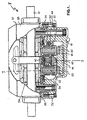
- the brake 8 of Fig. 1 is of the type comprising a caliper housing 10 that straddles a disc or rotor 12 mounted on an axle of the vehicle to be braked (not shown).
- the brake is actuated by mechanical movement of an input actuator such as an air cylinder (15, Figure 3 ).
- an input actuator such as an air cylinder (15, Figure 3 ).
- Such actuators are well known in the field of brake actuation.
- the actuator co-operates with the outer end of the operating shaft or 'op-shaft' 14 of the brake 8.
- the inner end of the op-shaft 14 is carried in a bearing attached to the lower end of inner housing part 16.
- the inner end of the op-shaft 14 has a pocket positioned eccentric to the op-shaft axis of rotation which, upon rotation, causes a reaction force to be transmitted to rollers 20.
- the rollers 20 in turn transmit the applied load to a pair of spaced inner tappet members 22.
- These inner tappet members 22 are screwed into engagement with associated outer tappet members 24 which apply the input load from the actuator to the rear of the inner braking lining 26, thus pressing the friction material of the inner friction lining 26 into frictional engagement with the disc 12.
- a reaction force is generated through this frictional engagement between the disc 12 and inner braking lining 26, that is fed back through the tappets 22 and 24, rollers 20 and op-shaft 14 which is supported by the inner housing part 16.
- the inner housing part 16 is secured to an outer housing part 28 by bridging bolts 30 and 32.
- the applied force being generated by movement of the op-shaft 14 is ultimately transmitted by reaction means to the outer housing part 28 which in turn presses the outer friction lining 34 into frictional engagement with the disc 12. Therefore, the disc 12, upon movement of the op-shaft 14, is clamped between the inner and outer friction linings 26 and 34 to generate a braking force for braking the vehicle under control of the applied input movement.
- the brake also includes an electric motor 40 adapted to drive via a reduction gearbox 42, shown here by way of example as a multi-stage planetary gearbox, a part of the telescopic tappet assembly that, upon rotation, acts to increase or reduce the overall length of the tappet assembly in accordance with the direction of rotation of the motor.
- a reduction gearbox 42 shown here by way of example as a multi-stage planetary gearbox
- Such extension or contraction adjusts the rest position of the brake applying member and therefore the clearance available between the friction linings and the brake rotor disc.
- the motor 40, gearbox 42 and tappet members 22 and 24 together constitute an adjuster mechanism of the brake
- a rotary encoder 44 that is driven from a part of the tappet assembly that moves upon adjustment.
- the encoder produces a signal which is arranged to be processed in an Electronic Control Unit (ECU) 80 where the output from the encoder is accumulated to provide a measure of the total position and therefore total movement of the adjustment mechanism, this output being proportional to the actual wear condition of the friction linings.
- ECU Electronic Control Unit
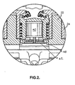
- the clearance data obtained is used by the ECU 80 to determine whether an adjustment of the clearance is required. If such an adjustment is required then the motor 40 is driven to the new position. As can be seen from figure 2 , the motor output drives through a cycloid gearbox assembly 42 onto a gear form 48 associated with the inner tappet member 22.
- the inner tappet member 22 is threadedly engaged with the outer tappet member 24 which is held against rotation. Rotation of the inner tappet member causes the overall tappet assembly to either extend or contract.
- the torque required to drive the tappet assembly to produce the aforementioned effect is substantially lower when the tappet assembly is not under any substantial axial loading as the friction level is drastically reduced between the two threaded members.
- the gearbox and tappet drives can now be produced from a material that is substantially lighter.
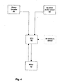
- FIG. 4 illustrates schematically the electrical components of the control system. It is apparent that at the heart of the system is ECU 80 that receives signals from the rotary encoder 44 and an op-shaft stroke sensor 82, and, in for the method of the second embodiment, an air pressure sensor 84 (shown in broken lines). The ECU 80 in turn may signal the driving of motor 40, and may receive signals from the motor or elsewhere on a motor drive circuit regarding the amount of current passing therethrough.
- the stroke sensor may be any suitable type of contacting or noncontacting sensor.
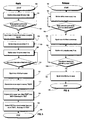
- Operation starts at step 100, and the system begins by monitoring the output of op-shaft stroke sensor 82 at predetermined intervals at step 102.
- the ECU 80 determines whether the signal from the stroke sensor 82 has reached a threshold value that indicates that the brake has been applied. If it has, at step 106 the ECU signals the motor 40 to lengthen the brake tappets. The ECU 80 then begins to monitor the current flowing through motor 140 at predetermined intervals and at step 110 senses when the current has increased above a predetermined threshold value (which is indicative of the motor stalling).
- the ECU 80 then signals motor drive to cease so that motor 40 is no longer seeking to extend the tappets.
- the ECU stores the stroke sensor output in a memory "SSON” and at step 116 subtracts the stroke sensor zero offset value "SSF” (i.e. a stroke sensor reading when the op-shaft 14 is in a released rest position) from SSON. This value is then stored in memory "SSC”.
- value SSC is then subtracted from a stored nominal clearance value "SSN” (i.e. the desired clearance value of disc to lining with the brake released) to equate to the amount of adjustment required to restore the clearance to the desired nominal clearance. This value is stored in memory "SSA" before the sequence of steps stops at 120.
- the sequence of steps starts at 122 with the brake applied.
- the ECU 80 monitors the stroke sensor 82 at predetermined intervals at step 124 and determines whether the brake has been released in response to the stroke sensor 82 providing a predetermined signal. Once this has occurred, the ECU 80 signals motor 40 drive to commence at step 128 in order to lengthen the tappets and monitors the extension of the tappets via the rotary encoder 44 until the tappets have been extended by a value equivalent to SSA, at which the ECU 80 signals motor drive to cease and the adjustment cycle stops at step 136.
- Figure 7 illustrates a control system and adjustment method according to a second embodiment of the present invention in which both measurement of the required amount of adjustment and the lengthening of the tappets occurs during the release of the brake.
- the sequence starts at step 138 and begins by monitoring the stroke sensor output at predetermined intervals at step 140.
- the ECU 80 monitors the air pressure in pneumatic actuator 15 using the air pressure sensor 84 at step 144, and at step 146 determines that the brake is being released, once the air pressure has fallen below a predetermined level at a predetermined rate.
- the ECU 80 signals the motor 40 to shorten the tappets. However, at this point, the motor torque is insufficient to overcome friction induced by the force passing through the tappets to the friction lining, causing the motor 40 to stall.
- the ECU 80 monitors the motor current at predetermined intervals at step 150 so it can determine when the current through the motor has dropped to a predetermined threshold value that indicates that the torque of the motor 40 is sufficient to drive the tappets.
- the ECU stores the stroke sensor output in memory SSOFF at step 154 before subtracting SSF (i.e. a stroke sensor reading when the op-shaft 14 is in a released rest position) from SSOFF at step 156 to give a value SSC which is stored in memory.
- SSF i.e. a stroke sensor reading when the op-shaft 14 is in a released rest position
- SSC is subtracted from a stored nominal clearance value SSN (e.g 0.25mm).
- SSN nominal clearance value
- the result is stored in memory SSA and equates to the amount by which the tappet members 22, 24 must be extended to return the brake to the correct running clearance.
- the ECU 80 signals motor 40 to drive to commence lengthening of the tappets and monitors the position of the rotary encoder 44 at predetermined intervals until the ECU determines that the tappets have extended by amount SSA. Once the tappets 22, 24 have extended by this amount, the ECU signals the motor to cease driving and the adjustment procedure stops at step 168.
- One advantage of this adjustment method is that the stroke sensor outputs SSON and SSOFF are measured at the end of the brake application cycle when the brake rotor and friction linings 26, 34 may be heated and have therefore expanded. Thus, the danger of "over adjustment” on the basis of values measured when the rotor 12 and linings 26, 34 are cold does not arise and the brake clearance is correctly set for the brakes when hot.
- the point at which the tappets come out of contact with the friction linings may be determined directly or indirectly from rotation of the drive motor 40, gears 46, or inner tappet members 22.
- the ECU may be programmed to only carry out the adjustment intermittently (e.g. every tenth brake application). Rather than seeking to correct the clearance fully each time it is determined that adjustment is needed, the ECU may be programmed to signal the motor to drive a fixed increment for each brake application, so the correct adjustment is only achieved after more than one brake application.
- the output from the tappet driven wear-out sensor or encoder 44 may be recorded or accumulated to provide a signal indicative of the worn condition of the friction linings.
- an alarm or other indication could then be issued.
- De-adjustment of the brake or retraction of the brake applying members is then instigated through use of an electrical or electronic switch (not shown). Once activated, the system determines whether the vehicle is in a correct condition to allow the brake to be 'opened' i.e. stationary. If this condition is satisfied then the electric motor 40 is energised so as to cause the brake-applying members to retract from the brake rotor 12. As the brake is no longer in correct adjustment, a flag is set so as to indicate to the ECU 80 that an adjustment is required.
- the out-of-adjustment flag is recognised and the brake is re-adjusted.
Landscapes
- Engineering & Computer Science (AREA)
- General Engineering & Computer Science (AREA)
- Mechanical Engineering (AREA)
- Braking Arrangements (AREA)
- Regulating Braking Force (AREA)
Applications Claiming Priority (2)
| Application Number | Priority Date | Filing Date | Title |
|---|---|---|---|
| GB0324243 | 2003-10-16 | ||
| GBGB0324243.5A GB0324243D0 (en) | 2003-10-16 | 2003-10-16 | A control system and method for a disc brake |
Publications (2)
| Publication Number | Publication Date |
|---|---|
| EP1524449A1 EP1524449A1 (en) | 2005-04-20 |
| EP1524449B1 true EP1524449B1 (en) | 2008-04-02 |
Family
ID=29559404
Family Applications (1)
| Application Number | Title | Priority Date | Filing Date |
|---|---|---|---|
| EP04256261A Expired - Lifetime EP1524449B1 (en) | 2003-10-16 | 2004-10-08 | A control system and method for the running clearance of a disc brake. |
Country Status (8)
| Country | Link |
|---|---|
| US (1) | US7152716B2 (enExample) |
| EP (1) | EP1524449B1 (enExample) |
| JP (1) | JP2005133941A (enExample) |
| CN (1) | CN1609738A (enExample) |
| AT (1) | ATE391248T1 (enExample) |
| BR (1) | BRPI0404375A (enExample) |
| DE (1) | DE602004012815T2 (enExample) |
| GB (1) | GB0324243D0 (enExample) |
Families Citing this family (27)
| Publication number | Priority date | Publication date | Assignee | Title |
|---|---|---|---|---|
| US8397883B2 (en) * | 2001-10-25 | 2013-03-19 | Lord Corporation | Brake with field responsive material |
| SE526946C2 (sv) * | 2003-06-13 | 2005-11-22 | Haldex Brake Prod Ab | Sensor system |
| US7475760B2 (en) * | 2005-10-04 | 2009-01-13 | Delphi Technologies, Inc. | Pad contact detection method |
| DE102005049786A1 (de) * | 2005-10-18 | 2007-04-19 | Knorr-Bremse Systeme für Nutzfahrzeuge GmbH | Scheibenbremse mit elektromotorischem Aktuator, vorzugsweise in selbstverstärkender Bauart |
| US8177308B2 (en) * | 2005-11-30 | 2012-05-15 | Goodrich Corporation | Controller for electromechanical braking system with running clearance adjustment and method |
| JP2008049800A (ja) * | 2006-08-24 | 2008-03-06 | Hitachi Ltd | 電動ブレーキ装置およびその制御方法 |
| US8146452B2 (en) * | 2007-11-12 | 2012-04-03 | Heidelberger Druckmaschinen Ag | Apparatus for driving a roller of a printing press and printing press having the apparatus |
| EP2225132B1 (de) * | 2007-12-21 | 2011-09-14 | Ipgate Ag | Bremsanlage mit mindestens einer förderungseinrichtung zum nachfördern von bremsflüssigkeit in die arbeitsräume eines bremskraftverstärkers |
| WO2010150387A1 (ja) | 2009-06-25 | 2010-12-29 | 株式会社Tbk | ディスクブレーキ装置の間隙調整機構 |
| DE102010025232A1 (de) * | 2010-06-26 | 2011-12-29 | Wabco Gmbh | Pneumatische Radbremse für ein Fahrzeug |
| DE102010032515A1 (de) * | 2010-07-28 | 2012-02-02 | Knorr-Bremse Systeme für Nutzfahrzeuge GmbH | Bremsverschleisssensor einer Scheibenbremse |
| KR101813965B1 (ko) * | 2011-05-16 | 2018-01-02 | 현대모비스 주식회사 | 전동 브레이크 장치의 디스크 패드 간극 제어 방법 |
| CN102384192B (zh) * | 2011-07-06 | 2013-05-08 | 隆中控股集团有限公司 | 一种汽车气压盘式制动器中的间隙自调机构 |
| KR101755700B1 (ko) | 2011-07-19 | 2017-07-07 | 현대자동차주식회사 | 에스-캠타입 브레이크 |
| EP2639473A1 (en) * | 2012-03-16 | 2013-09-18 | Meritor Heavy Vehicle Braking Systems (UK) Limited | Disc brake caliper |
| DE102012007021B3 (de) * | 2012-04-05 | 2013-08-29 | Knorr-Bremse Systeme für Nutzfahrzeuge GmbH | Schiebesattel-Scheibenbremse eines Kraftfahrzeugs |
| DE102013205142A1 (de) * | 2012-04-16 | 2013-10-17 | Schaeffler Technologies AG & Co. KG | Verfahren und Vorrichtung zur Referenzierung und Plausibilisierung einer Referenzposition eines Aktors |
| JP5970385B2 (ja) | 2013-01-25 | 2016-08-17 | 株式会社アドヴィックス | 車両の電動制動装置 |
| KR101808397B1 (ko) | 2013-03-11 | 2017-12-13 | 할덱스 브레이크 프로덕츠 에이비 | 디스크 브레이크, 디스크 브레이크와 같은 브레이크 작동 메커니즘과 브레이크 조정 방법 |
| JP6214230B2 (ja) * | 2013-06-11 | 2017-10-18 | Ntn株式会社 | 電動ブレーキ装置 |
| EP2998607A1 (en) * | 2014-09-16 | 2016-03-23 | Meritor Heavy Vehicle Braking Systems (UK) Limited | Method and system for setting a braking component running clearnace |
| DE102015210431A1 (de) * | 2015-06-08 | 2016-12-08 | Robert Bosch Gmbh | Verfahren zum Ansteuern einer Feststellbremse in einem Fahrzeug |
| ES2733451T3 (es) | 2016-08-25 | 2019-11-29 | Dellner Brakes Ab | Un dispositivo de frenado de tipo palanca |
| CN106895983B (zh) * | 2017-04-19 | 2023-09-12 | 中国计量大学 | 一种汽车制动间隙调整臂检测装置 |
| DE102018211239A1 (de) * | 2018-07-07 | 2020-01-09 | Robert Bosch Gmbh | Verfahren und Vorrichtung zum Betreiben eines Elektromotors für eine elektrische Bremseinrichtung |
| CN111503189B (zh) * | 2020-04-08 | 2022-03-11 | 奇瑞商用车(安徽)有限公司 | 一种制动轮缸与摩擦片间隙调整装置及制动摩擦片更换方法 |
| US11841058B2 (en) * | 2022-01-14 | 2023-12-12 | Ford Global Technologies, Llc | Methods and apparatus to determine brake pad wear |
Family Cites Families (17)
| Publication number | Priority date | Publication date | Assignee | Title |
|---|---|---|---|---|
| US4804073A (en) | 1980-12-23 | 1989-02-14 | Allied-Signal Inc. | Electrically operated disc brake with back-off protector |
| US4995483A (en) | 1989-12-18 | 1991-02-26 | Aircraft Braking Systems Corporation | Motor position feedback controlled electrically actuated aircraft brake |
| DE19536695A1 (de) | 1995-09-30 | 1997-04-03 | Teves Gmbh Alfred | System zum Steuern oder Regeln einer elektromechanischen Bremse |
| JP3837195B2 (ja) * | 1996-12-26 | 2006-10-25 | 曙ブレーキ工業株式会社 | パッドクリアランス調整機構を備えた電動ブレーキとそのパッドクリアランス調整法 |
| DE19654729A1 (de) * | 1996-12-30 | 1999-07-22 | Bosch Gmbh Robert | Elektromotorische Bremsvorrichtung |
| US6003640A (en) | 1997-05-09 | 1999-12-21 | The B.F. Goodrich Company | Electronic braking system with brake wear measurement and running clearance adjustment |
| DE19730094A1 (de) * | 1997-07-14 | 1999-01-21 | Itt Mfg Enterprises Inc | System zum Steuern oder Regeln einer elektromechanischen Bremse |
| DE19861109B4 (de) * | 1998-06-12 | 2006-04-06 | Robert Bosch Gmbh | Verfahren und Vorrichtung zur Steuerung einer Fahrzeugbremsanlage |
| GB9823198D0 (en) * | 1998-10-24 | 1998-12-16 | Lucas Ind Plc | Vehicle brake having electric motor control of brake running clearance |
| JP4033281B2 (ja) * | 2000-09-06 | 2008-01-16 | 日産自動車株式会社 | 制動装置 |
| US6481542B2 (en) * | 2001-02-19 | 2002-11-19 | Meritor Heavy Vehicle Systems, Llc. | Brake adjuster |
| EP1386092B1 (de) * | 2001-04-26 | 2008-01-02 | KNORR-BREMSE SYSTEME FÜR NUTZFAHRZEUGE GmbH | Scheibenbremse mit elektromotorisch angetriebenem verschleissnachstellsystem |
| DE10150047A1 (de) * | 2001-10-10 | 2003-06-26 | Knorr Bremse Systeme | Steuerungsverfahren für Scheibenbremsen |
| DE10156503B4 (de) * | 2001-11-16 | 2006-06-14 | Knorr-Bremse Systeme für Nutzfahrzeuge GmbH | Steuerungsverfahren zur Steuerung eines Nachstellsystems einer Scheibenbremse und Steuereinrichtung |
| JP2003194119A (ja) * | 2001-12-28 | 2003-07-09 | Nissan Motor Co Ltd | 電動ブレーキ装置 |
| EP1476673B1 (de) * | 2002-02-13 | 2005-09-21 | KNORR-BREMSE SYSTEME FÜR NUTZFAHRZEUGE GmbH | Scheibenbremse mit elektromotorisch angetriebener nachstellvorrichtung und verfahren zur steuerung einer scheibenbremse |
| DE10214669B4 (de) * | 2002-04-03 | 2014-01-23 | Knorr-Bremse Systeme für Schienenfahrzeuge GmbH | Verfahren und Vorrichtung zur Ansteuerung einer elektrisch betätigten Verschleißnachstelleinrichtung |
-
2003
- 2003-10-16 GB GBGB0324243.5A patent/GB0324243D0/en not_active Ceased
-
2004
- 2004-10-08 DE DE602004012815T patent/DE602004012815T2/de not_active Expired - Lifetime
- 2004-10-08 AT AT04256261T patent/ATE391248T1/de not_active IP Right Cessation
- 2004-10-08 EP EP04256261A patent/EP1524449B1/en not_active Expired - Lifetime
- 2004-10-15 BR BR0404375-8A patent/BRPI0404375A/pt not_active IP Right Cessation
- 2004-10-15 JP JP2004300970A patent/JP2005133941A/ja active Pending
- 2004-10-18 US US10/967,912 patent/US7152716B2/en not_active Expired - Lifetime
- 2004-10-18 CN CN200410084067.4A patent/CN1609738A/zh active Pending
Also Published As
| Publication number | Publication date |
|---|---|
| US7152716B2 (en) | 2006-12-26 |
| GB0324243D0 (en) | 2003-11-19 |
| DE602004012815D1 (de) | 2008-05-15 |
| ATE391248T1 (de) | 2008-04-15 |
| US20050082122A1 (en) | 2005-04-21 |
| BRPI0404375A (pt) | 2005-06-14 |
| CN1609738A (zh) | 2005-04-27 |
| JP2005133941A (ja) | 2005-05-26 |
| EP1524449A1 (en) | 2005-04-20 |
| DE602004012815T2 (de) | 2009-04-30 |
Similar Documents
| Publication | Publication Date | Title |
|---|---|---|
| EP1524449B1 (en) | A control system and method for the running clearance of a disc brake. | |
| US6293370B1 (en) | Vehicle brake having electric motor control of brake running clearance | |
| EP0995921B1 (en) | Vehicle brake having a brake de-adjust control switch | |
| US7413061B2 (en) | Method and device for controlling an electrically actuated wear adjuster | |
| EP1233202B1 (en) | Brake adjuster | |
| CA1230063A (en) | Electric actuators | |
| US11448275B2 (en) | Technique for operating a vehicle brake having a hydraulic service brake and an electric parking brake | |
| US5975250A (en) | Apparatus and method for detecting the thickness of a brake lining | |
| KR100574903B1 (ko) | 브레이크 마모 측정기구, 작동 간극 조절기구 및 복수의 전기 모터-작동기 램 조립체를 갖춘 전자식 항공기 브레이크 시스템 | |
| EP1852628B1 (en) | Disc brake wear adjuster | |
| EP0125870B1 (en) | Electric actuators | |
| US9127735B2 (en) | Friction brake | |
| CN100408396C (zh) | 驻车制动器及其控制方法 | |
| CN108291593B (zh) | 盘式制动器的电磨损补偿调整装置、相应的盘式制动器和用于测量、调节气隙和测量磨损的方法 | |
| EP1762746A2 (en) | Brake monitoring and control system | |
| EP0789156B1 (en) | Brake condition monitoring means | |
| WO1992021542A1 (en) | Cable operated electromechanical brake and system therefor | |
| EP0504965A1 (en) | Electrically actuated brake | |
| KR20250040730A (ko) | 브레이크의 상태를 검출하기 위한 방법, 브레이크 및 브레이크를 갖는 브레이크 시스템 | |
| GB2310015A (en) | Vehicle brake assemblies | |
| US12590611B2 (en) | System for providing a brake force | |
| KR100380400B1 (ko) | 자동차의 브레이크 간극 자동조정장치 및 그 방법 |
Legal Events
| Date | Code | Title | Description |
|---|---|---|---|
| PUAI | Public reference made under article 153(3) epc to a published international application that has entered the european phase |
Free format text: ORIGINAL CODE: 0009012 |
|
| AK | Designated contracting states |
Kind code of ref document: A1 Designated state(s): AT BE BG CH CY CZ DE DK EE ES FI FR GB GR HU IE IT LI LU MC NL PL PT RO SE SI SK TR |
|
| AX | Request for extension of the european patent |
Extension state: AL HR LT LV MK |
|
| 17P | Request for examination filed |
Effective date: 20050923 |
|
| AKX | Designation fees paid |
Designated state(s): AT BE BG CH CY CZ DE DK EE ES FI FR GB GR HU IE IT LI LU MC NL PL PT RO SE SI SK TR |
|
| GRAP | Despatch of communication of intention to grant a patent |
Free format text: ORIGINAL CODE: EPIDOSNIGR1 |
|
| GRAS | Grant fee paid |
Free format text: ORIGINAL CODE: EPIDOSNIGR3 |
|
| GRAA | (expected) grant |
Free format text: ORIGINAL CODE: 0009210 |
|
| AK | Designated contracting states |
Kind code of ref document: B1 Designated state(s): AT BE BG CH CY CZ DE DK EE ES FI FR GB GR HU IE IT LI LU MC NL PL PT RO SE SI SK TR |
|
| REG | Reference to a national code |
Ref country code: GB Ref legal event code: FG4D |
|
| REG | Reference to a national code |
Ref country code: CH Ref legal event code: EP Ref country code: IE Ref legal event code: FG4D |
|
| REF | Corresponds to: |
Ref document number: 602004012815 Country of ref document: DE Date of ref document: 20080515 Kind code of ref document: P |
|
| REG | Reference to a national code |
Ref country code: SE Ref legal event code: TRGR |
|
| PG25 | Lapsed in a contracting state [announced via postgrant information from national office to epo] |
Ref country code: SI Free format text: LAPSE BECAUSE OF FAILURE TO SUBMIT A TRANSLATION OF THE DESCRIPTION OR TO PAY THE FEE WITHIN THE PRESCRIBED TIME-LIMIT Effective date: 20080402 |
|
| NLV1 | Nl: lapsed or annulled due to failure to fulfill the requirements of art. 29p and 29m of the patents act | ||
| PG25 | Lapsed in a contracting state [announced via postgrant information from national office to epo] |
Ref country code: PT Free format text: LAPSE BECAUSE OF FAILURE TO SUBMIT A TRANSLATION OF THE DESCRIPTION OR TO PAY THE FEE WITHIN THE PRESCRIBED TIME-LIMIT Effective date: 20080903 Ref country code: FI Free format text: LAPSE BECAUSE OF FAILURE TO SUBMIT A TRANSLATION OF THE DESCRIPTION OR TO PAY THE FEE WITHIN THE PRESCRIBED TIME-LIMIT Effective date: 20080402 Ref country code: BG Free format text: LAPSE BECAUSE OF FAILURE TO SUBMIT A TRANSLATION OF THE DESCRIPTION OR TO PAY THE FEE WITHIN THE PRESCRIBED TIME-LIMIT Effective date: 20080702 Ref country code: ES Free format text: LAPSE BECAUSE OF FAILURE TO SUBMIT A TRANSLATION OF THE DESCRIPTION OR TO PAY THE FEE WITHIN THE PRESCRIBED TIME-LIMIT Effective date: 20080713 Ref country code: NL Free format text: LAPSE BECAUSE OF FAILURE TO SUBMIT A TRANSLATION OF THE DESCRIPTION OR TO PAY THE FEE WITHIN THE PRESCRIBED TIME-LIMIT Effective date: 20080402 |
|
| PG25 | Lapsed in a contracting state [announced via postgrant information from national office to epo] |
Ref country code: PL Free format text: LAPSE BECAUSE OF FAILURE TO SUBMIT A TRANSLATION OF THE DESCRIPTION OR TO PAY THE FEE WITHIN THE PRESCRIBED TIME-LIMIT Effective date: 20080402 Ref country code: AT Free format text: LAPSE BECAUSE OF FAILURE TO SUBMIT A TRANSLATION OF THE DESCRIPTION OR TO PAY THE FEE WITHIN THE PRESCRIBED TIME-LIMIT Effective date: 20080402 |
|
| ET | Fr: translation filed | ||
| PG25 | Lapsed in a contracting state [announced via postgrant information from national office to epo] |
Ref country code: DK Free format text: LAPSE BECAUSE OF FAILURE TO SUBMIT A TRANSLATION OF THE DESCRIPTION OR TO PAY THE FEE WITHIN THE PRESCRIBED TIME-LIMIT Effective date: 20080402 Ref country code: CZ Free format text: LAPSE BECAUSE OF FAILURE TO SUBMIT A TRANSLATION OF THE DESCRIPTION OR TO PAY THE FEE WITHIN THE PRESCRIBED TIME-LIMIT Effective date: 20080402 |
|
| PLBE | No opposition filed within time limit |
Free format text: ORIGINAL CODE: 0009261 |
|
| STAA | Information on the status of an ep patent application or granted ep patent |
Free format text: STATUS: NO OPPOSITION FILED WITHIN TIME LIMIT |
|
| PG25 | Lapsed in a contracting state [announced via postgrant information from national office to epo] |
Ref country code: SK Free format text: LAPSE BECAUSE OF FAILURE TO SUBMIT A TRANSLATION OF THE DESCRIPTION OR TO PAY THE FEE WITHIN THE PRESCRIBED TIME-LIMIT Effective date: 20080402 Ref country code: RO Free format text: LAPSE BECAUSE OF FAILURE TO SUBMIT A TRANSLATION OF THE DESCRIPTION OR TO PAY THE FEE WITHIN THE PRESCRIBED TIME-LIMIT Effective date: 20080402 Ref country code: BE Free format text: LAPSE BECAUSE OF FAILURE TO SUBMIT A TRANSLATION OF THE DESCRIPTION OR TO PAY THE FEE WITHIN THE PRESCRIBED TIME-LIMIT Effective date: 20080402 |
|
| 26N | No opposition filed |
Effective date: 20090106 |
|
| PG25 | Lapsed in a contracting state [announced via postgrant information from national office to epo] |
Ref country code: EE Free format text: LAPSE BECAUSE OF FAILURE TO SUBMIT A TRANSLATION OF THE DESCRIPTION OR TO PAY THE FEE WITHIN THE PRESCRIBED TIME-LIMIT Effective date: 20080402 |
|
| PGFP | Annual fee paid to national office [announced via postgrant information from national office to epo] |
Ref country code: FR Payment date: 20081014 Year of fee payment: 5 |
|
| PG25 | Lapsed in a contracting state [announced via postgrant information from national office to epo] |
Ref country code: MC Free format text: LAPSE BECAUSE OF NON-PAYMENT OF DUE FEES Effective date: 20081031 |
|
| REG | Reference to a national code |
Ref country code: CH Ref legal event code: PL |
|
| PG25 | Lapsed in a contracting state [announced via postgrant information from national office to epo] |
Ref country code: CY Free format text: LAPSE BECAUSE OF FAILURE TO SUBMIT A TRANSLATION OF THE DESCRIPTION OR TO PAY THE FEE WITHIN THE PRESCRIBED TIME-LIMIT Effective date: 20080402 |
|
| PG25 | Lapsed in a contracting state [announced via postgrant information from national office to epo] |
Ref country code: LI Free format text: LAPSE BECAUSE OF NON-PAYMENT OF DUE FEES Effective date: 20081031 Ref country code: CH Free format text: LAPSE BECAUSE OF NON-PAYMENT OF DUE FEES Effective date: 20081031 Ref country code: IE Free format text: LAPSE BECAUSE OF NON-PAYMENT OF DUE FEES Effective date: 20081008 |
|
| REG | Reference to a national code |
Ref country code: FR Ref legal event code: ST Effective date: 20100630 |
|
| PG25 | Lapsed in a contracting state [announced via postgrant information from national office to epo] |
Ref country code: FR Free format text: LAPSE BECAUSE OF NON-PAYMENT OF DUE FEES Effective date: 20091102 Ref country code: HU Free format text: LAPSE BECAUSE OF FAILURE TO SUBMIT A TRANSLATION OF THE DESCRIPTION OR TO PAY THE FEE WITHIN THE PRESCRIBED TIME-LIMIT Effective date: 20081003 Ref country code: LU Free format text: LAPSE BECAUSE OF NON-PAYMENT OF DUE FEES Effective date: 20081008 |
|
| PG25 | Lapsed in a contracting state [announced via postgrant information from national office to epo] |
Ref country code: TR Free format text: LAPSE BECAUSE OF FAILURE TO SUBMIT A TRANSLATION OF THE DESCRIPTION OR TO PAY THE FEE WITHIN THE PRESCRIBED TIME-LIMIT Effective date: 20080402 |
|
| PG25 | Lapsed in a contracting state [announced via postgrant information from national office to epo] |
Ref country code: GR Free format text: LAPSE BECAUSE OF FAILURE TO SUBMIT A TRANSLATION OF THE DESCRIPTION OR TO PAY THE FEE WITHIN THE PRESCRIBED TIME-LIMIT Effective date: 20080703 |
|
| PGFP | Annual fee paid to national office [announced via postgrant information from national office to epo] |
Ref country code: GB Payment date: 20141027 Year of fee payment: 11 |
|
| GBPC | Gb: european patent ceased through non-payment of renewal fee |
Effective date: 20151008 |
|
| PG25 | Lapsed in a contracting state [announced via postgrant information from national office to epo] |
Ref country code: GB Free format text: LAPSE BECAUSE OF NON-PAYMENT OF DUE FEES Effective date: 20151008 |
|
| P01 | Opt-out of the competence of the unified patent court (upc) registered |
Effective date: 20230531 |
|
| PGFP | Annual fee paid to national office [announced via postgrant information from national office to epo] |
Ref country code: SE Payment date: 20231027 Year of fee payment: 20 Ref country code: IT Payment date: 20231023 Year of fee payment: 20 Ref country code: DE Payment date: 20231027 Year of fee payment: 20 |
|
| REG | Reference to a national code |
Ref country code: DE Ref legal event code: R071 Ref document number: 602004012815 Country of ref document: DE |
|
| REG | Reference to a national code |
Ref country code: SE Ref legal event code: EUG |