EP1523693B1 - Optische vorrichtung zum vereinigen von lichtstrahlen - Google Patents
Optische vorrichtung zum vereinigen von lichtstrahlen Download PDFInfo
- Publication number
- EP1523693B1 EP1523693B1 EP03764919A EP03764919A EP1523693B1 EP 1523693 B1 EP1523693 B1 EP 1523693B1 EP 03764919 A EP03764919 A EP 03764919A EP 03764919 A EP03764919 A EP 03764919A EP 1523693 B1 EP1523693 B1 EP 1523693B1
- Authority
- EP
- European Patent Office
- Prior art keywords
- light
- light beams
- reference beam
- beams
- adjusted
- Prior art date
- Legal status (The legal status is an assumption and is not a legal conclusion. Google has not performed a legal analysis and makes no representation as to the accuracy of the status listed.)
- Expired - Lifetime
Links
- 230000003287 optical effect Effects 0.000 title claims description 27
- 238000012545 processing Methods 0.000 claims description 14
- 238000001514 detection method Methods 0.000 claims description 12
- 238000000034 method Methods 0.000 claims description 10
- 238000005286 illumination Methods 0.000 description 11
- 238000004621 scanning probe microscopy Methods 0.000 description 7
- 239000013307 optical fiber Substances 0.000 description 6
- 230000008859 change Effects 0.000 description 4
- 230000008878 coupling Effects 0.000 description 4
- 238000010168 coupling process Methods 0.000 description 4
- 238000005859 coupling reaction Methods 0.000 description 4
- 230000003595 spectral effect Effects 0.000 description 4
- 238000005259 measurement Methods 0.000 description 3
- 238000011144 upstream manufacturing Methods 0.000 description 3
- 230000001276 controlling effect Effects 0.000 description 2
- 238000012937 correction Methods 0.000 description 2
- 230000005284 excitation Effects 0.000 description 2
- 239000007850 fluorescent dye Substances 0.000 description 2
- 230000035939 shock Effects 0.000 description 2
- 238000002560 therapeutic procedure Methods 0.000 description 2
- 229910000831 Steel Inorganic materials 0.000 description 1
- 230000004075 alteration Effects 0.000 description 1
- 230000008901 benefit Effects 0.000 description 1
- 230000033228 biological regulation Effects 0.000 description 1
- 238000010276 construction Methods 0.000 description 1
- 238000013461 design Methods 0.000 description 1
- 238000000605 extraction Methods 0.000 description 1
- 238000012986 modification Methods 0.000 description 1
- 230000004048 modification Effects 0.000 description 1
- 238000012544 monitoring process Methods 0.000 description 1
- 239000002245 particle Substances 0.000 description 1
- 230000010287 polarization Effects 0.000 description 1
- 238000001959 radiotherapy Methods 0.000 description 1
- 230000001105 regulatory effect Effects 0.000 description 1
- 239000010959 steel Substances 0.000 description 1
Images


Classifications
-
- G—PHYSICS
- G02—OPTICS
- G02B—OPTICAL ELEMENTS, SYSTEMS OR APPARATUS
- G02B27/00—Optical systems or apparatus not provided for by any of the groups G02B1/00 - G02B26/00, G02B30/00
- G02B27/10—Beam splitting or combining systems
- G02B27/14—Beam splitting or combining systems operating by reflection only
- G02B27/145—Beam splitting or combining systems operating by reflection only having sequential partially reflecting surfaces
-
- G—PHYSICS
- G02—OPTICS
- G02B—OPTICAL ELEMENTS, SYSTEMS OR APPARATUS
- G02B21/00—Microscopes
- G02B21/0004—Microscopes specially adapted for specific applications
- G02B21/002—Scanning microscopes
-
- G—PHYSICS
- G02—OPTICS
- G02B—OPTICAL ELEMENTS, SYSTEMS OR APPARATUS
- G02B26/00—Optical devices or arrangements for the control of light using movable or deformable optical elements
- G02B26/08—Optical devices or arrangements for the control of light using movable or deformable optical elements for controlling the direction of light
- G02B26/0875—Optical devices or arrangements for the control of light using movable or deformable optical elements for controlling the direction of light by means of one or more refracting elements
-
- G—PHYSICS
- G02—OPTICS
- G02B—OPTICAL ELEMENTS, SYSTEMS OR APPARATUS
- G02B27/00—Optical systems or apparatus not provided for by any of the groups G02B1/00 - G02B26/00, G02B30/00
- G02B27/10—Beam splitting or combining systems
- G02B27/12—Beam splitting or combining systems operating by refraction only
- G02B27/123—The splitting element being a lens or a system of lenses, including arrays and surfaces with refractive power
Definitions
- the invention relates to an optical device for adjusting at least one light beam.
- the invention relates to a method for adjusting at least one light beam to a desired beam path and a method for combining a light beam and at least one further light beam.
- samples are often prepared with multiple markers, for example several different fluorescent dyes, to excite them simultaneously with an illumination light beam that includes light of multiple excitation wavelengths.
- the illumination light beam the light beams of several lasers are usually combined with usually a plurality of dichroic beam splitters connected in series.
- dichroic beam splitters connected in series.
- From the German Offenlegungsschrift DE 198 35 068 A1 is a microscope, in particular laser scanning microscope with illumination over one and / or several wavelengths known, wherein controlling the intensity of at least one wavelength via at least one arranged in the illumination beam path rotatable interference filter, wherein the at least one wavelength at least partially reflected out of the illumination beam path and several filters for different wavelengths can be arranged behind one another in the illumination beam path.
- the U.S. Patent 4,627,725 discloses an optical system incorporating the Orientation or position of the optical axis monitored.
- a plurality of partial beams are emitted from the illuminating light steel, which extends in the optical axis, which are directed to corresponding light detectors.
- the detectors are position detectors, can be determined by the position of the illumination light beam to the optical axis.
- active control elements tilt mirrors
- the light rays of a light source in the Scanning microscope coupled and adjusted to the beam path of the scanning microscope, and a sample illuminated with the light beam to observe the reflected or fluorescent light emitted by the sample.
- the focus of an illumination light beam is moved by means of a controllable beam deflection device, generally by tilting two mirrors, in an object plane, wherein the deflection axes are usually perpendicular to one another, so that one mirror deflects in the x direction and the other in the y direction.
- the tilting of the mirror is accomplished, for example, with the help of galvanometer actuators.
- the power of the light coming from the object is measured as a function of the position of the scanning beam.
- the control elements are equipped with sensors for determining the current mirror position.
- an object with the focus of a light beam is scanned in three dimensions.
- a confocal scanning microscope generally comprises a light source, a focusing optics with which the light of the source is focused on a pinhole - the so-called excitation diaphragm, a beam splitter, a beam deflector for beam control, a microscope optics, a detection diaphragm and the detectors for detecting the detection - or fluorescent light.
- the illumination light is coupled in via a beam splitter.
- the fluorescence or reflection light coming from the object passes back to the beam splitter via the beam deflector, passes through it, and is subsequently focused onto the detection aperture behind which the detectors are located.
- Detection light that does not come directly from the focus region takes a different light path and does not pass through the detection aperture, so as to obtain point information that results in a three-dimensional image by sequentially scanning the object.
- a three-dimensional image is achieved by layered image data acquisition, wherein the path of the scanning light beam on or in the object ideally describes a meander. (Scanning a line in the x-direction at a constant y-position, then pause x-scan and swing by y-adjustment to the next line to be scanned and then, at constant y-position, scan this line in negative x-direction, etc.).
- the sample stage or the objective is displaced after the scanning of one layer and the next layer to be scanned is thus brought into the focal plane of the objective.
- the coupling of the light beams for illuminating a sample into a microscope is a very critical point with regard to the adjustment, in particular since the position and the propagation direction of several light beams of different wavelengths must exactly follow the desired beam path of the microscope.
- the adjustment of a direct coupling is difficult and, on the other hand, not very reliable, since, due to relatively long light paths, even the smallest fluctuations in the design can lead to disturbances, which make costly readjustments necessary.
- optical fibers are used to transport the light rays from the light source or from the light sources to the microscope to reduce the problem of adjusting the optical fiber extraction, which is expensive but less sensitive to misalignments due to the shorter light paths.
- the adjustment problem is not solved thereby, but possibly reduced, but other difficulties arise, such as the fluctuation of the polarization direction of the light beams.
- DE 198 16 302 C1 discloses a device for radiotherapy of tissue particles.
- the device includes an optical element that merges a target and a therapy beam into a beam path.
- the optical element is a plate with two optically active surfaces, it being possible to decouple a partial beam from the therapy beam on at least one of the surfaces.
- the split partial beams are used as reference beams for controlling the light output.
- the known arrangements for combining light beams of different wavelengths have the disadvantage that they are inflexible with respect to a wavelength change. Besides, it is not possible too determine whether the merged rays are actually exactly collinear. This remains usually consuming way the user or the service technician left. If the light beams combined to form an illuminating light beam do not run largely collinearly, aberrations, in particular unsightly artifacts and brightness fluctuations, occur in scanning microscopy.
- an optical device which is characterized in that two reference beams per light beam reach a position detector and can be detected there.
- the position detector is connected to a processing unit.
- the processing unit is connected to two control elements per light beam to be adjusted and controls tilting of the adjusting elements that exiting the optical component, at least one light beam on a desired axis (89) and wherein the control elements of the first interface for splitting off the at least first reference beam are connected upstream ,
- a further embodiment of the invention is a method for combining a light beam and at least one further light beam which can be used flexibly and reliably, in particular at different wavelengths.
- the invention has the advantage that a simple and reliable adjustment of the light beams of a light source or a plurality of light sources to the desired beam path is made possible.
- a way to effectively monitor the adjustment is given. Consequently, in the scanning microscopy by avoiding misalignments, a particular stability of the image quality with simultaneous flexible applicability with respect to the illumination light wavelength is given.
- a means for splitting off a first reference beam is a first interface and as a further means for splitting off the second reference beam, a second interface is provided.
- a prism is provided, wherein preferably two of the side surfaces form the first and second interface.
- an acousto-optical component which can be embodied, for example, as an acousto-optic modulator (AOM), as an acousto-optic tunable filter (AOTF) or as an acousto-optic deflector (AOD).
- AOM acousto-optic modulator
- AOTF acousto-optic tunable filter
- AOD acousto-optic deflector
- the acousto-optic component in a preferred embodiment, can cause the combination of light rays.
- the acousto-optical component is used for spectral splitting and is, for example, a prism with a first and a upstream second interface.
- the acousto-optical component can also serve to vary the light output of the combined light beams separately and to adapt them to the respective application.
- the position detector is calibrated for different detectable positions.
- Each possible beam position is preferably associated with a detectable set of positions; There is also a corresponding set of nominal positions for the nominal beam position.
- the propagation direction and / or the position of the light beams to be adjusted are optimized until the desired positions are detected. If the detected positions deviate from the desired positions due to an external disturbance, for example, a readjustment can take place via a control loop so that the light beams to be adjusted can be actively held on the desired beam path.
- the first reference beam and the second reference beam are split off at different locations.
- the means for splitting off a first reference beam and the further means for splitting off the second reference beam are components of a single optical component, for example two side surfaces of a prism.
- This embodiment is particularly stable and resistant to vibrations and shocks.
- the device or device according to the invention is preferably designed in a compact monolithic construction.
- the means for cleaving and the position detector are preferably assigned to each other spatially fixed, so that, since only a relative measurement must be performed, a particular stability is given.
- the propagation direction and / or the position of the light beams or of the light beam are variable with adjusting elements, which may be designed, for example, as a gimbal-mounted tilting mirror.
- adjusting elements are also provided.
- controllable light beam deflecting tilt mirrors are used.
- the adjusting elements are connected upstream of the means for splitting off a first reference beam.
- actuating elements can be controlled and / or regulated as a function of the positions detected using the position detector (s) is particularly advantageous.
- a control or regulation can be realized, which automatically optimizes the adjustment of the light beam (the light beams) or the collinearity of the combined light beams.
- the position detector is designed as a CCD detector. It can also be designed, for example, as a photodiode line, as a photomultiplier array, or else contain a plurality of individual detectors.
- the reference beams are detected together with a position detector, so that only relative measurements within the position detector are necessary.
- the position of the first reference beam and the position of the second reference beam are detected independently of one another and made usable for corrections of the beam angles and positions.
- the positions of the reference beams are detected simultaneously, which is particularly advantageous with respect to external disturbances, such as vibrations and shocks, because no change in the spatial situation falsifies the measurement.
- the light powers of the reference beams can be determined independently of one another and used for corrections of the light powers, which is of particular importance in scanning microscopy.
- At least one further light beam is adjustable to the desired beam path.
- the light beam and other light beams may have different wavelengths.
- a component for spectral splitting provided, which is preferably arranged between the adjusting elements and the means for splitting off a first reference beam.
- the component for spectral splitting can be designed, for example, as a plane-parallel plate, as a prism or as a grating.
- a dispersive element is provided, which is arranged between the means for splitting off a first reference beam and the further means for splitting off the second reference beam.
- the means for splitting off the further light beam splits off a further first reference beam and the further means for splitting off from the further light beam a further second reference beam, the further first and the further second reference beam being detectable by the position detector are, and wherein the propagation direction and / or the position of the second light beam in dependence on the detected positions of the further first and the further second reference beam is adjustable to the desired beam path.
- the propagation direction and / or the position of the first and the further light beam are independently adjustable.
- further adjusting elements for adjusting the propagation direction and / or the position of the further light beam are provided.
- the further adjusting elements are controllable in dependence on the detected positions of the further first and the further second reference beam.
- the device for adjusting is particularly well suited for coupling light beams into a microscope, in particular a scanning microscope, which can be designed as a confocal scanning microscope.
- the desired beam path may be the beam path of a microscope, a scanning microscope or a confocal scanning microscope.
- the device simultaneously serves for decoupling the detection light emanating from the sample.
- the light beams emitted by the light source initially run collinear and are spatially spectrally separated before the first interface with a component for spectral splitting.
- This embodiment is particularly interesting when the light source comprises an optical fiber that carries all the primary light beams together.
- FIG. 1 schematically shows an optical device 1 for combining at least two light beams, namely a first light beam 3 and a second light beam 5.
- the light beams 3, 5 are emitted by a light source 7, which includes a first laser 9 and a second laser 11 ,
- the light beams 3, 5 have different wavelengths.
- the first light beam 3 strikes a first adjusting element 13, which includes a first tilting mirror 15 which can be tilted in two axes. Subsequently, the first light beam 3 impinges on a second adjusting element 17, which includes a second tilting mirror 19 which can be tilted in two axes.
- the second control element 17 deflects the first light beam 3 to a means for splitting off a first reference beam 25, which is designed as a first boundary surface 21 of a prism 23.
- a first reference beam 25 is split off by partial reflection and impinges on the position detector 27, which is designed as a CCD array 29.
- the first light beam 3 passes through the prism 23 and encounters a further means for splitting off a second reference beam 33, which is designed as a second interface 31.
- a second reference beam 33 is split off by partial reflection and, after a total internal reflection at a third interface 35 and after passing the first interface 21 on the position detector 27.
- Analog passes the second light beam 5, from a third actuator 37 with a third tilting mirror 39 and a fourth adjusting element 41 with a fourth tilting mirror 43 out.
- a further first reference beam 45 is split off at the second interface 31, a further second reference beam 47 and directed to the position detector 27.
- a lens 49 is arranged, which focuses the reference beams on the CCD array 29. It is also possible to provide a slight defocusing to achieve better resolution by interpolation over several pixels.
- the position detector From the different points of incidence of the reference beams on the CCD array 29, it is possible to deduce the locations and angles at which the light beams 3, 5 impinge on the first interface 21 and second interface 31, and thus on the position and the propagation direction the light beams 3, 5 after leaving the prism 23.
- the position detector generates position signals, which it passes on to a processing unit 51.
- the processing unit 51 controls the adjusting elements 13, 17, 37, 41 until the light beams 3, 5 emerging from the prism run sufficiently collinearly.
- the path difference between the first reference beam 25 and the second reference beam 33 or between the other first reference beam 45 and the further second reference beam 47 is preferably about 20 mm, resulting in a change in distance of about 20 microns on the position detector per mrad Angle difference leads. 20 ⁇ m corresponds approximately to the distance between two pixels on conventional CCD detectors.
- an acousto-optical component which is designed as AOTF 53, provided in order to adjust the light output of the light beams 3, 5 separately.
- the first light beam 3 and the reference beams 25, 33 split off from it are shown by dashed lines in the drawing.
- the second light beam 5 and the split off from him reference beams 45, 47 are shown dotted in the drawing.
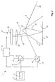
- Fig. 2 shows a device according to the invention, which is particularly suitable for a plurality of coaxially extending light beams 3, 5 having different wavelengths, for example, after the coupling of an optical fiber to adjust to a common desired beam path and to hold there by a suitable control.
- the light beams 3, 5 impinge on a first adjusting element 13, which includes a first tilting mirror 15, which can be tilted in two axes, and subsequently on a second actuating element 17, which contains a second tilting mirror 19 which can be tilted in two axes.
- a first adjusting element 13 which includes a first tilting mirror 15, which can be tilted in two axes
- second actuating element 17 which contains a second tilting mirror 19 which can be tilted in two axes.
- the position and the propagation direction of the light beams 3, 5 can be adjusted.
- the light beams 3, 5 strike a first plane-parallel plate 55, which spatially separates the light beams 3, 5 spatially.
- a second plane-parallel plate 57 the light beams 3, 5 are reunited.
- the second plane-parallel plate 57 has a first boundary surface 21 which splits off a first reference beam 25 from the first light beam 3 and a further first reference beam 45 from the second light beam 5.
- the light beams 3, 5 After passing through the second plane-parallel plate 57, the light beams 3, 5 impinge on a means for splitting off a second reference beam 33 and another second reference beam 47, namely a second interface 31, the first light beam 3 a second reference beam 33 and of the second light beam 5 splits off another second reference beam 47. All reference beams are guided to a position detector 27, which is designed as a CCD array 29.
- the position detector 27 generates position signals, which it passes on to a processing work 51.
- the processing work 51 controls the adjusting elements 13, 17 until the light beams 3, 5 emerging from the second plane-parallel plate have the desired position and run in the desired direction.
- the current position and the current direction of propagation of the light beams 3, 5 is permanently or regularly compared with the desired position and the desired direction of propagation and optionally automatically corrected by the processing unit 51 via them actuators 13, 17.
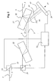
- Fig. 3 shows schematically a scanning microscope, which is designed as a confocal scanning microscope.
- the light beams 3, 5 coming from a light source 7, which is designed as a multiline laser, are coupled to the optical system 59 for transport into an optical fiber 61.
- the decoupling takes place with a further optics 63, which largely collimates the light beams 3, 5.
- the light beams 3, 5 are automatically adjusted to the beam path of the scanning microscope.
- the light beams 3, 5 from a beam splitter 67 to a gimbal-mounted scanning mirror 69, the light beams 3, 5 through the scanning optics 71, the tube optics 73 and the lens 75 passes through or through the sample 77.
- Sample 77 is labeled with several fluorescent dyes.
- the detection light beam 79 emanating from the sample 77 passes through the objective 75, the tube optics 73 and the scanning optics 71 and via the scanning mirror 69 to the beam splitter 67, passes it and, after passing through the detection aperture 81, strikes a detector 83 which is designed as a multi-band detector , and the electrical, to the power of the detection light beam 79 proportional electrical detection signals generated. These are forwarded to the PC 85.
- the detection signals are processed in the PC 85 and the user on a Monitor 87 displayed in the form of an image of the sample 77.
- the scanning microscope is insensitive to misalignments and allows a quick, uncomplicated change of the light source or the optical fiber.
- the 4 shows a device for adjusting a light beam 3 to a desired beam path, which is illustrated in the drawing by a desired optical axis 89.
- the light beam 3 strikes a first adjusting element 13, which includes a first tilting mirror 15 which can be tilted in two axes.
- the first light beam 3 impinges on a second adjusting element 17, which includes a second tilting mirror 19 which can be tilted in two axes.
- the second control element 17 directs the first light beam 3 to a means for splitting off a first reference beam 25, which is designed as a first boundary surface 21 of a prism 23.
- a first reference beam 25 is split off by partial reflection and impinges on the position detector 27, which is designed as a CCD array 29.
- the first light beam 3 passes through the prism 23 and encounters a further means for splitting off a second reference beam 33, which is designed as a second interface 31.
- a second reference beam 33 is split off by partial reflection and impinges upon a total internal reflection at a third interface 35 and after passing the first interface 21 on the position detector 27.
- a lens 49 is arranged, the reference beams on the CCD array 29 focused. It is also possible to provide a slight defocusing to achieve better resolution by interpolation over several pixels.
- the position detector From the different points of incidence of the reference beams on the CCD array 29, it is possible to deduce the locations and the angles at which the light beam 3 impinges on the first interface 21 or second interface 31 and thus on the position and on the propagation direction of the Light beam 3 after leaving the prism 23.
- the position detector generates position signals, which it passes on to a processing unit 51. Based on the transferred position data, the processing unit 51 controls the adjusting elements 13, 17 until the light beam 5 emerging from the prism is directed onto the desired beam path or the desired axis 89 runs.
Landscapes
- Physics & Mathematics (AREA)
- General Physics & Mathematics (AREA)
- Optics & Photonics (AREA)
- Chemical & Material Sciences (AREA)
- Analytical Chemistry (AREA)
- Microscoopes, Condenser (AREA)
Description
- Die Erfindung betrifft eine optische Vorrichtung zum Justieren von mindestens einem Lichtstrahl.
- Außerdem betrifft die Erfindung ein Verfahren zum Justieren mindestens eines Lichtstrahles auf einen Sollstrahlengang und ein Verfahren zum Vereinigen von einem Lichtstrahl und zumindest einem weiteren Lichtstrahl.
- In der Optik tritt häufig das Problem auf, Lichtstrahlen, insbesondere unterschiedlicher Wellenlänge, kollinear zu vereinigen.
- Beispielsweise in der Scanmikroskopie werden Proben oft mit mehreren Markem, beispielsweise mehreren unterschiedlichen Fluoreszenzfarbstoffen präpariert, um diese simultan mit einem Beleuchtungslichtstrahl, der Licht mehrerer Anregungswellenlängen beinhaltet, anzuregen. Zur Erzeugung des Beleuchtungslichtstrahles werden üblicherweise die Lichtstrahlen mehrerer Laser mit meist mehreren, hintereinander geschalteten, dichroitischen Strahlteilern vereinigt. Aus der
Deutschen Offenlegungsschrift DE 198 29 953 A1 ist beispielsweise ein Scanmikroskop mit einem dichroitischen Strahlvereiniger für infrarotes und ultraviolettes Licht bekannt. - Aus der
Deutschen Offenlegungsschrift DE 198 35 068 A1 ist ein Mikroskop, insbesondere Laser-Scanning-Mikroskop mit Beleuchtung über eine und/oder mehrere Wellenlängen bekannt, wobei eine Steuerung der Intensität mindestens einer Wellenlänge über mindestens einen im Beleuchtungsstrahlengang angeordneten drehbaren Interferenzfilter erfolgt, wobei die mindestens eine Wellenlänge zumindest teilweise aus dem Beleuchtungsstrahlengang herausreflektiert wird und mehrere Filter für unterschiedliche Wellenlängen hintereinander im Beleuchtungsstrahlengang angeordnet sein können. - Das
U.S. Patent 4,627,725 offenbart ein optisches System, das die Ausrichtung bzw. Lage der optischen Achse überwacht. Dazu werden aus dem Beleuchtungslichtstahl, der in der optischen Achse verläuft mehrere Teilstrahlen ausgekoppelt, die auf entsprechende Lichtdetektoren gerichtet werden. Die Detektoren sind Positionsdetektore, über die Lage des Beleuchtungslichtstrahls zur optischen Achse ermittelt werden kann. Dieses Dokument offenbart jedoch nicht, dass aktive Stellelemente (Kippspiegel) vorhanden sind, mit denen mindestens ein beliebig eingestrahlter Lichtstrahl auf die optische Achse bzw. auf die in einem optischen System ausgezeichnete Strahlachse justiert werden kann. - In der Scanmikroskopie werden die Lichtstrahlen einer Lichtquelle in das Scanmikroskop eingekoppelt und auf den Strahlengang des Scanmikroskops justiert, und eine Probe mit dem Lichtstrahl beleuchtet, um das von der Probe emittierte Reflexions- oder Fluoreszenzlicht zu beobachten. Der Fokus eines Beleuchtungslichtstrahles wird mit Hilfe einer steuerbaren Strahlablenkeinrichtung, im Allgemeinen durch Verkippen zweier Spiegel, in einer Objektebene bewegt, wobei die Ablenkachsen meist senkrecht aufeinander stehen, so dass ein Spiegel in x-, der andere in y-Richtung ablenkt. Die Verkippung der Spiegel wird beispielsweise mit Hilfe von Galvanometer-Stellelementen bewerkstelligt. Die Leistung des vom Objekt kommenden Lichtes wird in Abhängigkeit von der Position des Abtaststrahles gemessen. Üblicherweise werden die Stellelemente mit Sensoren zur Ermittlung der aktuellen Spiegelstellung ausgerüstet.
- Speziell in der konfokalen Scanmikroskopie wird ein Objekt mit dem Fokus eines Lichtstrahles in drei Dimensionen abgetastet.
- Ein konfokales Rastermikroskop umfasst im Allgemeinen eine Lichtquelle, eine Fokussieroptik, mit der das Licht der Quelle auf eine Lochblende - die sog. Anregungsblende - fokussiert wird, einen Strahlteiler, eine Strahlablenkeinrichtung zur Strahlsteuerung, eine Mikroskopoptik, eine Detektionsblende und die Detektoren zum Nachweis des Detektions- bzw. Fluoreszenzlichtes. Das Beleuchtungslicht wird über einen Strahlteiler eingekoppelt. Das vom Objekt kommende Fluoreszenz- oder Reflexionslicht gelangt über die Strahlablenkeinrichtung zurück zum Strahlteiler, passiert diesen, um anschließend auf die Detektionsblende fokussiert zu werden, hinter der sich die Detektoren befinden. Detektionslicht, das nicht direkt aus der Fokusregion stammt, nimmt einen anderen Lichtweg und passiert die Detektionsblende nicht, so dass man eine Punktinformation erhält, die durch sequentielles Abtasten des Objekts zu einem dreidimensionalen Bild führt. Meist wird ein dreidimensionales Bild durch schichtweise Bilddatennahme erzielt, wobei die Bahn des Abtastlichtstrahles auf bzw. in dem Objekt idealerweise einen Mäander beschreibt. (Abtasten einer Zeile in x-Richtung bei konstanter y-Position, anschließend x-Abtastung anhalten und per y-Verstellung auf die nächste abzutastende Zeile schwenken und dann, bei konstanter y-Position, diese Zeile in negativer x-Richtung abtasten u.s.w.). Um eine schichtweise Bilddatennahme zu ermöglichen, wird der Probentisch oder das Objektiv nach dem Abtasten einer Schicht verschoben und so die nächste abzutastende Schicht in die Fokusebene des Objektivs gebracht.
- Die Einkopplung der Lichtstrahlen zur Beleuchtung einer Probe in ein Mikroskop ist in Bezug auf die Justierung eine sehr kritische Stelle, insbesondere da die Lage und die Ausbreitungsrichtung meist mehrerer Lichtstrahlen unterschiedlicher Wellenlängen exakt dem Sollstrahlengang des Mikroskops folgen müssen. Die Justierung einer Direkteinkopplung ist einerseits schwierig und andererseits meist nicht sehr zuverlässig, da aufgrund relativ langer Lichtwege schon kleinste Schwankungen im Aufbau zu Störungen führen, die aufwendige Nachjustierungen erforderlich machen. Oft werden zum Transport der Lichtstrahlen von der Lichtquelle bzw. von den Lichtquellen zu dem Mikroskop Lichtleitfasern verwendet, um das Problem auf eine Justierung der Lichtleitfaserauskopplung zu reduzieren, die zwar auch aufwendig, jedoch aufgrund der kürzeren Lichtwege weniger empfindlich gegen Dejustierungen ist. Das Justierproblem wird hierdurch jedoch nicht gelöst, sondern allenfalls vermindert, wobei jedoch andere Schwierigkeiten, wie die Schwankung der Polarisationsrichtung der Lichtstrahlen entstehen.
-
DE 198 16 302 C1 offenbart eine Einrichtung zur Strahlentherapie von Gewebeteilchen. Die Einrichtung beinhaltet ein optisches Element, das einen Ziel und einen Therapiestrahl zu einem Strahlengang zusammen führt. Das optische Element ist eine Platte mit zwei optisch wirksamen Flächen, wobei an mindestens einer der Flächen ein Teilstrahl aus dem Therapiestrahl auskoppelbar ist. Die abgespaltenen Teilstrahlen werden als Referenzstrahlen zur Regelung der Lichtleistung genutzt. - Die bekannten Anordnungen zum Vereinigen von Lichtstrahlen unterschiedlicher Wellenlänge haben den Nachteil, dass sie in Bezug auf einen Wellenlängenwechsel unflexibel sind. Außerdem ist es nicht möglich zu ermitteln, ob die vereinigten Strahlen tatsächlich exakt kollinear verlaufen. Dies bleibt in der Regel aufwendiger Weise dem Benutzer bzw. dem Servicetechniker überlassen. Verlaufen die zu einem Beleuchtungslichtstrahl vereinigten Lichtstrahlen nicht weitgehend kollinear, so kommt es in der Scanmikroskopie zu Abbildungsfehlern, insbesondere zu unschönen Artefakten und Helligkeitsschwankungen.
- Es ist die Aufgabe der Erfindung, eine optische Vorrichtung zum Justieren von mindestens einem Lichtstrahl vorzuschlagen, die flexibel insbesondere bei verschiedenen Wellenlängen einsetzbar ist und die gleichzeitig eine effektive und wirksame Überwachung der Justierung ermöglicht.
- Die Aufgabe wird durch eine optische Vorrichtung gelöst, die dadurch gekennzeichnet ist, dass zwei Referenzstrahlen pro Lichtstrahl zu einem Positionsdetektor gelangen und dort detektierbar sind. Der Positionsdetektor ist mit einer Verarbeitungseinheit verbunden. Die Verarbeitungseinheit ist mit zwei Stellelementen pro zu justierenden Lichtstrahl verbunden und steuert derart Kippspiegel der Stellelemente dass der aus dem optischen Bauteil austretende, mindestens eine Lichtstrahl auf einer Sollachse (89) verläuft und wobei die Stellelemente der ersten Grenzfläche zum Abspalten des mindestens ersten Referenzstrahles vorgeschaltet sind.
- Es ist eine weitere Aufgabe der Erfindung ein Verfahren zum Justieren mindestens eines Lichtstrahles auf einen Sollstrahlengang anzugeben, das effizient und zuverlässig und reproduzierbar ausführbar und das universell einsetzbar ist.
- Diese Aufgabe wird durch ein Verfahren gelöst, das die Merkmale des Anspruchs 10 umfasst.
- Eine Weitergestaltung der Erfindung ist ein Verfahren zum Vereinigen von einem Lichtstrahl und zumindest einem weiteren Lichtstrahl das flexibel und zuverlässig insbesondere bei verschiedenen Wellenlängen einsetzbar ist.
- Die Erfindung hat insbesondere in der Scanmikroskopie den Vorteil, dass eine einfache und zuverlässige Justierung der Lichtstrahlen einer Lichtquelle bzw. mehrerer Lichtquellen auf den Sollstrahlengang ermöglicht ist. Außerdem ist eine Möglichkeit zur wirksamen Überwachung der Justierung gegeben. Folglich ist in der Scanmikroskopie durch die Vermeidung von Dejustierungen eine besondere Stabilität der Bildqualität bei gleichzeitiger flexibler Einsetzbarkeit in Bezug auf die Beleuchtungslicht-Wellenlänge gegeben.
- Als Mittel zum Abspalten eines ersten Referenzstrahles ist eine erste Grenzfläche und als weiteres Mittel zum Abspalten des zweiten Referenzstrahles ist eine zweite Grenzfläche vorgesehen. In einer bevorzugten Ausgestaltung ist ein Prisma vorgesehen, wobei vorzugsweise zwei der Seitenflächen die erste und zweite Grenzfläche bilden.
- In einer Variante ist ein akustooptisches Bauteil vorgesehen, das beispielsweise als ein akustooptischer Modulator (AOM), als ein akustooptischer abstimmbarer Filter (AOTF) oder als ein akustooptischer Deflektor (AOD) ausgeführt sein kann. Das akustooptische Bauteil, kann in einer bevorzugten Ausgestaltung die Vereinigung von Lichtstrahlen bewirken. In einer anderen Ausführung dient das akustooptische Bauteil zur spektralen Aufspaltung und ist beispielsweise einem Prisma mit einer ersten und einer zweiten Grenzfläche vorgeordnet. Das akustooptische Bauteil kann auch dazu dienen die Lichtleistung der vereinigten Lichtstrahlen separat zu variieren und der jeweiligen Anwendung anzupassen.
- In einer bevorzugten Ausgestaltung ist der Positionsdetektor für verschiedene detektierbare Positionen kalibriert. Jeder möglichen Strahllage ist vorzugsweise eine detektierbarer Satz von Positionen zugeordnet; auch zur Sollstrahllage gibt es einen korrespondierenden Satz von Sollpositionen. Die Ausbreitungsrichtung und/oder die Lage der zu justierenden Lichtstrahlen werden optimiert, bis die Sollpositionen detektiert werden. Weichen die detektierten Positionen, beispielsweise auf Grund einer äußeren Störung von den Sollpositionen ab, kann über eine Regelschleife eine Nachjustierung erfolgen, so dass die zu justierenden Lichtstrahlen aktiv auf dem Sollstrahlengang gehalten werden können. Vorzugsweise wird der erste Referenzstrahl und der zweite Referenzstrahl an verschiedenen Orten abgespalten.
- Das Mittel zum Abspalten eines ersten Referenzstrahles und das weitere Mittel zum Abspalten des zweiten Referenzstrahles sind Bestandteile eines einzigen optischen Bauteils, beispielsweise zwei Seitenflächen eines Prismas. Diese Ausgestaltung ist besonders stabil und resistent gegen Vibrationen und Erschütterungen. Die erfindungsgemäße Einrichtung bzw. Vorrichtung ist vorzugsweise in einer kompakten monolithischen Bauweise ausgeführt. Die Mittel zum Abspalten und der Positionsdetektor sind einander vorzugsweise raumfest zugeordnet ist, so dass, da nur eine Relativmessung ausgeführt werden muss, eine besondere Stabilität gegeben ist.
- Die Ausbreitungsrichtung und/oder die Lage der Lichtstrahlen bzw. des Lichtstrahls sind mit Stellelementen, die beispielsweise als kardanisch aufgehängte Kippspiegel ausgeführt sein können, veränderbar. In einer besonders bevorzugten Ausführungsvariante ist vorgesehen, dass die Einfallswinkel und/oder die Orte unter denen die Lichtstrahlen auf die erste Grenzfläche treffen, einstellbar sind. Hierzu sind ebenfalls Stellelemente vorgesehen. Als Stellelemente werden steuerbare lichtstrahlablenkende Kippspiegel verwendet. Die Stellelemente sind dem Mittel zum Abspalten eines ersten Referenzstrahles vorgeschaltet.
- Eine Ausführungsform, in der die Stellelemente in Abhängigkeit von den mit dem Positionsdetektor(en) detektierten Positionen steuer- und/oder regelbar sind, ist besonders vorteilhaft. Mit einer solchen Ausgestaltung ist eine Steuerung bzw. Regelung realisierbar, die automatisch die Justierung des Lichtstrahles (der Lichtstrahlen) bzw. die Kollinearität der vereinigten Lichtstrahlen optimiert.
- In einer bevorzugten Ausgestaltung ist der Positionsdetektor als CCD-Detektor ausgeführt. Er kann beispielsweise auch als Photodiodenzeile, als Photomultiplierarray ausgeführt sein oder auch mehrere Einzeldetektoren beinhalten. Vorzugsweise werden die Referenzstrahlen gemeinsam mit einem Positionsdetektor detektiert, so dass nur noch Relativmessungen innerhalb des Positionsdetektors nötig sind.
- Vorzugsweise werden die Position des ersten Referenzstrahles und die Position des zweiten Referenzstrahles unabhängig voneinander detektiert und für Korrekturen der Strahlwinkel und -lagen nutzbar gemacht. In einer bevorzugten Ausgestaltung werden die Positionen der Referenzstrahlen gleichzeitig detektiert, was in Bezug auf äußere Störungen, wie Vibrationen und Erschütterungen, besonders vorteilhaft ist, weil keine Änderung der räumlichen Situation die Messung verfälscht.
- In einer besonderen Ausführung sind die Lichtleistungen der Referenzstrahlen unabhängig voneinander ermittelbar und für Korrekturen der Lichtleistungen verwendbar, was insbesondere in der Scanmikroskopie von Wichtigkeit ist.
- In einer bevorzugten Ausgestaltung der Einrichtung zum Justieren ist mindestens ein weiterer Lichtstrahl auf den Sollstrahlengang justierbar. Der Lichtstrahl und weitere Lichtstrahlen können verschiedene Wellenlängen aufweisen.
- Vor dem Mittel zum Abspalten eines ersten Referenzstrahles ist in einer bevorzugten Ausgestaltung ein Bauteil zur spektralen Aufspaltung vorgesehen, das vorzugsweise zwischen den Stellelementen und dem Mittel zum Abspalten eines ersten Referenzstrahles angeordnet ist. Das Bauteil zur spektralen Aufspaltung kann beispielsweise als planparallele Platte, als Prisma oder als Gitter ausgeführt sein.
- In einer anderen Ausführung ist ein dispersives Element vorgesehen, das zwischen dem Mittel zum Abspalten eines ersten Referenzstrahles und dem weiteren Mittel zum Abspalten des zweiten Referenzstrahles angeordnet ist.
- In einer bevorzugten Ausgestaltung der Einrichtung zum Justieren spaltet das Mittel zum Abspalten von dem weiteren Lichtstrahl einen weiteren ersten Referenzstrahl ab und das weitere Mittel zum Abspalten von dem weiteren Lichtstrahl einen weiteren zweiten Referenzstrahl, wobei der weitere erste und der weitere zweite Referenzstrahl von dem Positionsdetektor detektierbar sind, und wobei die Ausbreitungsrichtung und/oder die Lage des zweiten Lichtstrahles in Abhängigkeit von den detektierten Positionen des weiteren ersten und des weiteren zweiten Referenzstrahls auf den Sollstrahlengang einstellbar ist. Vorzugsweise sind die Ausbreitungsrichtung und/oder die Lage des ersten und des weiteren Lichtstrahles unabhängig voneinander einstellbar. In einer Variante sind weitere Stellelemente zum Einstellen der Ausbreitungsrichtung und/oder der Lage des weiteren Lichtstrahles vorgesehen. Vorzugsweise sind die weiteren Stellelemente in Abhängigkeit von den detektierten Positionen des weiteren ersten und des weiteren zweiten Referenzstrahles steuerbar.
- Die Einrichtung zum Justieren eignet sich besonders gut zur Einkopplung von Lichtstrahlen in ein Mikroskop, insbesondere ein Scanmikroskop, das als konfokales Scanmikroskop ausgeführt sein kann. Demgemäss kann der Sollstrahlengang der Strahlengang eines Mikroskops, eines Scanmikroskops oder ein konfokales Scanmikroskops sein. In einer anderen vorteilhaften Ausgestaltung dient die Einrichtung gleichzeitig zum Auskoppeln des von der Probe ausgehenden Detektionslichtes.
- In einer bevorzugten Ausgestaltung verlaufen die von der Lichtquelle emittierten Lichtstrahlen zunächst kollinear und werden vor der ersten Grenzfläche mit einem Bauteil zur spektralen Aufspaltung räumlich spektral getrennt. Diese Ausführung ist insbesondere dann interessant, wenn die Lichtquelle eine Lichtleitfaser umfasst, die alle primären Lichtstrahlen gemeinsam transportiert.
- In der Zeichnung ist der Erfindungsgegenstand schematisch dargestellt und wird anhand der Figuren nachfolgend beschrieben, wobei gleich wirkende Bauteile mit denselben Bezugszeichen versehen sind. Dabei zeigen:
- Fig. 1
- eine optische Vorrichtung zum Vereinigen von zumindest zwei Lichtstrahlen,
- Fig. 2
- eine Einrichtung zum Justieren,
- Fig. 3
- ein erfindungsgemäßes Scanmikroskop.
- Fig. 4
- eine weitere Einrichtung zum Justieren.
- Fig. 1 zeigt schematisch eine optische Vorrichtung 1 zum Vereinigen von zumindest zwei Lichtstrahlen, nämlich einem ersten Lichtstrahl 3 und einem zweiten Lichtstrahl 5. Die Lichtstrahlen 3, 5 werden von einer Lichtquelle 7, die einen ersten Laser 9 und einen zweiten Laser 11 beinhaltet emittiert. Die Lichtstrahlen 3, 5 weisen unterschiedliche Wellenlängen auf. Der erste Lichtstrahl 3 trifft auf ein erstes Stellelement 13, das einen in zwei Achsen verkippbaren ersten Kippspiegel 15 beinhaltet. Anschließend trifft der erste Lichtstrahl 3 auf ein zweites Stellelement 17, das einen in zwei Achsen verkippbaren zweiten Kippspiegel 19 beinhaltet. Das zweite Stellelement 17 lenkt den ersten Lichtstrahl 3 auf ein Mittel zum Abspalten eines ersten Referenzstrahles 25, das als erste Grenzfläche 21 eines Prismas 23 ausgeführt ist. An der ersten Grenzfläche 21 wird ein erster Referenzstrahl 25 durch Teilreflexion abgespalten und trifft auf den Positionsdetektor 27, der als CCD-Array 29 ausgeführt ist. Nach Passieren der ersten Grenzfläche 21 durchläuft der erste Lichtstrahl 3 das Prisma 23 und trifft auf ein weiteres Mittel zum Abspalten eines zweiten Referenzstrahles 33, das als zweite Grenzfläche 31 ausgeführt ist. An der zweiten Grenzfläche 31 wird ein zweiter Referenzstrahl 33 durch Teilreflexion abgespalten und trifft nach einer totalinternen Reflexion an einer dritten Grenzfläche 35 und nach Passieren der ersten Grenzfläche 21 auf den Positionsdetektor 27. Analog verläuft der zweite Lichtstrahl 5, von einem dritten Stellelement 37 mit einem dritten Kippspiegel 39 und einem vierten Stellelement 41 mit einem vierten Kippspiegel 43 geführt. Von dem zweiten Lichtstrahl 5 wird an der ersten Grenzfläche 21 ein weiterer erster Referenzstrahl 45 an der zweiten Grenzfläche 31 ein weiterer zweiter Referenzstrahl 47 abgespalten und zu dem Positionsdetektor 27 gelenkt. Vor dem Positionsdetektor ist eine Linse 49 angeordnet, die die Referenzstrahlen auf das CCD-Array 29 fokussiert. Es ist auch möglich, eine leichte Defokussierung vorzusehen, um durch Interpolation über mehrere Pixel eine bessere Auflösung zu erreichen. Aus den verschiedenen Auftrefforten der Referenzstrahlen auf dem CCD-Array 29 kann auf die Orte und auf die Winkel, unter denen die Lichtstrahlen 3, 5 auf die erste Grenzfläche 21 bzw. zweite Grenzfläche 31 treffen, geschlossen werden und somit auf die Lage und die Ausbreitungsrichtung der Lichtstrahlen 3, 5 nach dem Verlassen des Prismas 23. Der Positionsdetektor erzeugt Positionssignale, die er an eine Verarbeitungseinheit 51 weitergibt. Anhand der übergebenen Positionsdaten steuert die Verarbeitungseinheit 51 die Stellelemente 13, 17, 37, 41, bis die aus dem Prisma austretenden Lichtstrahlen 3, 5 hinreichend kollinear verlaufen. Der Wegunterschied zwischen dem ersten Referenzstrahl 25 und dem zweiten Referenzstrahl 33 bzw. zwischen dem weiteren ersten Referenzstrahl 45 und dem weiteren zweiten Referenzstrahl 47 beträgt vorzugsweise etwa 20 mm, was zu einer Abstandsänderung von ca. 20 µm auf dem Positionsdetektor pro mrad Winkeldifferenz führt. 20 µm entspricht etwa dem Abstand zweier Pixel auf üblichen CCD Detektoren.
- Im weiteren Strahlengang der vereinigten Lichtstrahlen 3, 5 ist ein akustooptisches Bauteil, das als AOTF 53 ausgeführt ist, vorgesehen, um die Lichtleistung der Lichtstrahlen 3, 5 separat einstellen zu können. Der erste Lichtstrahl 3 und die von ihm abgespaltenen Referenzstrahlen 25, 33 sind in der Zeichnung gestrichelt dargestellt. Der zweite Lichtstrahl 5 und die von ihm abgespaltenen Referenzstrahlen 45, 47 sind in der Zeichnung gepunktet dargestellt.
- Fig. 2 zeigt eine erfindungsgemäße Vorrichtung, die insbesondere dazu geeignet ist, mehrere koaxial verlaufenden Lichtstrahlen 3, 5, die unterschiedliche Wellenlängen aufweisen, beispielsweise nach der Auskopplung aus einer Lichtleitfaser, auf einen gemeinsamen Sollstrahlengang zu justieren und dort durch eine geeignete Regelung zu halten.
- Die Lichtstrahlen 3, 5 treffen auf ein erstes Stellelement 13, das einen in zwei Achsen verkippbaren ersten Kippspiegel 15 beinhaltet und anschließend auf ein zweites Stellelement 17, das einen in zwei Achsen verkippbaren zweiten Kippspiegel 19 beinhaltet. Mit Hilfe der Stellelemente 13, 17 lässt sich die Lage und die Ausbreitungsrichtung der Lichtstrahlen 3, 5 einstellen. Nach Passieren der Stellelemente 13, 17 treffen die Lichtstrahlen 3, 5 auf eine erste planparallele Platte 55, die die Lichtstrahlen 3, 5 räumlich spektral trennt. Mit Hilfe einer zweiten planparallelen Platte 57 werden die Lichtstrahlen 3, 5 wieder vereinigt. Die zweite planparallele Platte 57 weist als Mittel zum Abspalten eines ersten Referenzstrahles 25 und eines weiteren ersten Referenzstrahles 45 eine erste Grenzfläche 21 auf, die von dem ersten Lichtstrahl 3 einen ersten Referenzstrahl 25 und von dem zweiten Lichtstrahl 5 einen weiteren ersten Referenzstrahl 45 abspaltet. Nach Durchlaufen der zweiten planparallelen Platte 57 treffen die Lichtstrahlen 3, 5 auf ein Mittel zum Abspalten eines zweiten Referenzstrahles 33 und eines weiteren zweiten Referenzstrahles 47, nämlich eine zweite Grenzfläche 31, die von dem ersten Lichtstrahl 3 einen zweiten Referenzstrahl 33 und von dem zweiten Lichtstrahl 5 einen weiteren zweiten Referenzstrahl 47 abspaltet. Alle Referenzstrahlen werden zu einem Positionsdetektor 27 geführt, der als CCD-Array 29 ausgeführt ist.
- Der Positionsdetektor 27 erzeugt Positionssignale, die er an eine Verarbeitungsarbeit 51 weitergibt. Anhand der übergebenen Positionsdaten steuert die Verarbeitungsarbeit 51 die Stellelemente 13, 17, bis die aus der zweiten planparallelen Platte austretenden Lichtstrahlen 3, 5 die gewünschte Lage haben und in die gewünschte Richtung verlaufen. Die aktuelle Lage und die aktuelle Ausbreitungsrichtung der Lichtstrahlen 3, 5 wird permanent oder regelmäßig mit der gewünschten Lage und der gewünschten Ausbreitungsrichtung verglichen und ggf. automatisch von der Verarbeitungseinheit 51 über sie Stellelemente 13, 17 korrigiert.
- Fig. 3 zeigt schematisch ein Scanmikroskop, das als konfokales Scanmikroskop ausgeführt ist. Die von einer Lichtquelle 7, die als Mehrlinienlaser ausgeführt ist, kommenden Lichtstrahlen 3, 5 werden mit der Optik 59 zum Transport in eine Lichtleitfaser 61 eingekoppelt. Die Auskopplung erfolgt mit einer weiteren Optik 63, die die Lichtstrahlen 3, 5 weitgehend kollimiert. Mit der folgenden Vorrichtung, deren Funktionsweise bereits in Bezug auf Fig. 2 beschrieben wurde, werden die Lichtstrahlen 3, 5 automatisch auf den Strahlengang des Scanmikroskops justiert.
- Nach Passieren der Beleuchtungslochblende 65 werden die Lichtstrahlen 3, 5 von einen Strahlteiler 67 zu einem kardanisch aufgehängten Scanspiegel 69, der die Lichtstrahlen 3, 5 durch die Scanoptik 71, die Tubusoptik 73 und das Objektiv 75 hindurch über bzw. durch die Probe 77 führt. Die Probe 77 ist mit mehreren Fluoreszenzfarbstoffen markiert. Der von der Probe 77 ausgehende Detektionslichtstrahl 79 gelangt durch das Objektiv 75, die Tubusoptik 73 und die Scanoptik 71 hindurch und über den Scanspiegel 69 zum Strahlteiler 67, passiert diesen und trifft nach Passieren der Detektionsblende 81 auf einen Detektor 83, der als Multibanddetektor ausgeführt ist, und der elektrische, zur Leistung des Detektionslichtstrahls 79 proportionale elektrische Detektionssignale erzeugt. Diese werden an den PC 85 weitergeleitet. Die Detektionssignale werden im PC 85 aufbereitet und dem Benutzer auf einem Monitor 87 in Form eines Abbildes der Probe 77 angezeigt. Das Scanmikroskop ist unempfindlich gegen Dejustierungen und erlaubt einen schnellen, unkomplizierten Wechsel der Lichtquelle bzw. der Lichtleitfaser.
- Fig. 4 zeigt eine Einrichtung zum Justieren eines Lichtstrahles 3 auf einen Sollstrahlengang, der in der Zeichnung durch eine optische Sollachse 89 illustriert ist. Der Lichtstrahl 3 trifft auf ein erstes Stellelement 13, das einen in zwei Achsen verkippbaren ersten Kippspiegel 15 beinhaltet. Anschließend trifft der erste Lichtstrahl 3 auf ein zweites Stellelement 17, das einen in zwei Achsen verkippbaren zweiten Kippspiegel 19 beinhaltet. Das zweite Stellelement 17 lenkt den ersten Lichtstrahl 3 auf ein Mittel zum Abspalten eines ersten Referenzstrahles 25, das als erste Grenzfläche 21 eines Prismas 23 ausgeführt ist. An der ersten Grenzfläche 21 wird ein erster Referenzstrahl 25 durch Teilreflexion abgespalten und trifft auf den Positionsdetektor 27, der als CCD-Array 29 ausgeführt ist. Nach Passieren der ersten Grenzfläche 21 durchläuft der erste Lichtstrahl 3 das Prisma 23 und trifft auf ein weiteres Mittel zum Abspalten eines zweiten Referenzstrahles 33, das als zweite Grenzfläche 31 ausgeführt ist. An der zweiten Grenzfläche 31 wird ein zweiter Referenzstrahl 33 durch Teilreflexion abgespalten und trifft nach einer totalinternen Reflexion an einer dritten Grenzfläche 35 und nach Passieren der ersten Grenzfläche 21 auf den Positionsdetektor 27. Vor dem Positionsdetektor ist eine Linse 49 angeordnet, die die Referenzstrahlen auf das CCD-Array 29 fokussiert. Es ist auch möglich, eine leichte Defokussierung vorzusehen, um durch Interpolation über mehrere Pixel eine bessere Auflösung zu erreichen. Aus den verschiedenen Auftrefforten der Referenzstrahlen auf dem CCD-Array 29 kann auf die Orte und auf die Winkel, unter denen der Lichtstrahl 3 auf die erste Grenzfläche 21 bzw. zweite Grenzfläche 31 treffen, geschlossen werden und somit auf die Lage und auf die Ausbreitungsrichtung des Lichtstrahls 3 nach dem Verlassen des Prismas 23. Der Positionsdetektor erzeugt Positionssignale, die er an eine Verarbeitungseinheit 51 weitergibt. Anhand der übergebenen Positionsdaten steuert die Verarbeitungseinheit 51 die Stellelemente 13, 17, bis der aus dem Prisma austretende Lichtstrahl 5 auf dem Sollstrahlengang bzw. der Sollachse 89 verläuft.
- Mit derselben Einrichtung können weitere Lichtstrahlen gleichzeitig auf den Sollstrahlengang justiert werden. Hierfür sind vorzugsweise weitere Stellelemente vorgesehen.
- Die Erfindung wurde in Bezug auf eine besondere Ausführungsform beschrieben. Es ist jedoch selbstverständlich, dass Änderungen und Abwandlungen durchgeführt werden können, ohne dabei den Schutzbereich der nachstehenden Ansprüche zu verlassen.
Claims (14)
- Optische Vorrichtung (1) zum Justieren von mindestens einem Lichtstrahl (3, 5), mit- einem optischen Bauteil (23, 57), das eine erste Grenzfläche (21) zum Abspalten mindestens eines ersten Referenzstrahles (25) von dem mindestens einen Lichtstrahl (3, 5), sowie eine weitere Grenzfläche (31) zum Abspalten mindestens eines zweiten Referenzstrahles (33) von dem mindestens einen Lichtstrahl (3, 5) umfasst,- einem Positionsdetektor (29),- einer Verarbeitungseinheit (51) und- pro zu justierendem Lichtstrahl zwei Stellelementen (13, 17, 37, 41) mit je mindestens einem Kippspiegel (15, 19, 39, 43),wobei
die Referenzstrahlen (25, 33) zu dem Positionsdetektor (29) gelangen und dort detektierbar sind, und der Positionsdetektor (29) mit der Verarbeitungseinheit (51) verbunden ist, und wobei
die Verarbeitungseinheit (51) mit den zwei Stellelementen (13, 17, 37, 41) pro zu justierenden Lichtstrahl (3, 5) verbunden ist und derart die Kippspiegel (15, 19, 39, 43) der Stellelemente (13, 17, 37, 41) steuert, dass der aus dem optischen Bauteil (23, 57) austretende, mindestens eine Lichtstrahl (3, 5) auf einer Sollachse (89) verläuft und wobei
die Stellelemente (13, 17, 37, 41) der ersten Grenzfläche (21) zum Abspalten des mindestens ersten Referenzstrahles (25) vorgeschaltet sind. - Vorrichtung nach Anspruch 1, dadurch gekennzeichnet, dass mindestens zwei Lichtstrahlen (3, 5) vorgesehen sind, wobei die mindestens zwei Lichtstrahlen (3, 5) unterschiedliche Wellenlängen aufweisen.
- Vorrichtung nach einem der Ansprüche 1 bis 2, dadurch gekennzeichnet, dass das optische Bauteil (29) ein Prisma ist.
- Vorrichtung nach einem der Ansprüche 1 bis 2, dadurch gekennzeichnet, dass die optische Vorrichtung ein akustooptisches Bauteil ist beinhaltet.
- Vorrichtung nach einem der Ansprüche 1 bis 4, dadurch gekennzeichnet, dass die Ausbreitungsrichtung und/oder die Lage des mindestens einen Lichtstrahls (3, 5) durch die Stellelemente (13, 17, 37, 41) einstellbar sind.
- Vorrichtung nach einem der Ansprüche 1 bis 5, dadurch gekennzeichnet, dass die Kippspiegel (15, 19, 39, 43) der Stellelemente (13, 17, 37, 41) in Abhängigkeit der durch den Positionsdetektor (29) detektierten Positionen steuerbar sind.
- Vorrichtung nach einem der Ansprüche 1 bis 6, dadurch gekennzeichnet, dass der Einfallswinkel, unter dem der mindestens eine Lichtstrahl (3, 5) auf die erste Grenzfläche (21) trifft durch die Kippspiegel (15, 19, 39, 43), einstellbar ist.
- Vorrichtung nach einem der Ansprüche 1 bis 7, dadurch gekennzeichnet, dass der Ort, an dem der mindestens eine Lichtstrahl (3, 5) auf die erste Grenzfläche (21) trifft durch die Kippspiegel (15, 19, 39, 43), einstellbar ist.
- Vorrichtung nach einem der Ansprüche 1 bis 8, dadurch gekennzeichnet, dass die optische Vorrichtung (1) Bestandteil eines Scanmikroskops ist, in das der justierte Lichtstrahl (3, 5) als Beleuchtungslichtstrahl einleitbar ist.
- Verfahren zum Justieren mindestens eines Lichtstrahles auf einen Sollstrahlengang (89), gekennzeichnet durch folgende Schritte:• Abspalten eines ersten Referenzstrahles (25) und eines zweiten Referenzstrahles (33) von je einem Lichtstrahl (3, 5), mit einem optischen Bauteil (23, 57), das eine erste Grenzfläche (21) und eine weitere Grenzfläche (31) zum Abspalten des ersten Referenzstrahles (25) und des zweiten Referenzstrahles (33) aufweist,• Detektieren des ersten Referenzstrahles (25) und des zweiten Referenzstrahles (33) mit einem Positionsdetektor (29), der in einer bekannten Position zum Sollstrahlengang (89) angeordnet ist, und• Einstellen der Ausbreitungsrichtung und/oder der Lage des mindestens einen Lichtstrahles (3, 5) in Abhängigkeit von den detektierten Positionen auf den Sollstrahlengang (89), wobei der Positionsdetektor (29) mit einer Verarbeitungseinheit (51) verbunden ist, und dass die Verarbeitungseinheit (51) mit zwei Stellelementen (13, 17, 37, 41) pro zu justierenden Lichtstrahl (3, 5) verbunden ist und dadurch Kippspiegel (15, 19, 39, 43) der Stellelemente (13, 17, 37, 41) derart gesteuert werden, dass der aus dem optischen Bauteil (23, 57) austretende, mindestens eine Lichtstrahl (3, 5) auf der Sollachse (89) verläuft.
- Verfahren nach Anspruch 10, dadurch gekennzeichnet, dass der Positionsdetektor (29) für verschiedene detektierbare Positionen kalibriert wird.
- Verfahren nach Anspruch 10, dadurch gekennzeichnet, dass die Position des ersten Referenzstrahles (25) und die Position des zweiten Referenzstrahles (33) unabhängig voneinander detektiert werden.
- Verfahren nach Anspruch 10, dadurch gekennzeichnet, dass die Lichtleistungen der Referenzstrahlen (25, 33) unabhängig voneinander ermittelt werden.
- Verfahren nach einem der Ansprüche 10 bis 13, dadurch gekennzeichnet, dass mindestens zwei Lichtstrahlen (3, 5) auf den Sollstrahlengang (89) justiert werden.
Applications Claiming Priority (3)
| Application Number | Priority Date | Filing Date | Title |
|---|---|---|---|
| DE10233074 | 2002-07-19 | ||
| DE10233074A DE10233074B4 (de) | 2002-07-19 | 2002-07-19 | Optische Vorrichtung zum Vereinigen von Lichtstrahlen und Scanmikroskop |
| PCT/EP2003/006236 WO2004010202A1 (de) | 2002-07-19 | 2003-06-13 | Optische vorrichtung zum vereinigen von lichtstrahlen |
Publications (2)
| Publication Number | Publication Date |
|---|---|
| EP1523693A1 EP1523693A1 (de) | 2005-04-20 |
| EP1523693B1 true EP1523693B1 (de) | 2007-08-01 |
Family
ID=30010266
Family Applications (1)
| Application Number | Title | Priority Date | Filing Date |
|---|---|---|---|
| EP03764919A Expired - Lifetime EP1523693B1 (de) | 2002-07-19 | 2003-06-13 | Optische vorrichtung zum vereinigen von lichtstrahlen |
Country Status (5)
| Country | Link |
|---|---|
| US (1) | US7428104B2 (de) |
| EP (1) | EP1523693B1 (de) |
| AU (1) | AU2003246422A1 (de) |
| DE (2) | DE10233074B4 (de) |
| WO (1) | WO2004010202A1 (de) |
Families Citing this family (17)
| Publication number | Priority date | Publication date | Assignee | Title |
|---|---|---|---|---|
| TWI364889B (en) * | 2005-11-11 | 2012-05-21 | Hon Hai Prec Ind Co Ltd | Laser device and laser system using the same |
| DE102007011305A1 (de) | 2007-03-06 | 2008-09-11 | Leica Microsystems Cms Gmbh | Vorrichtung und Verfahren zur Strahljustage in einem optischen Strahlengang |
| US10114213B2 (en) | 2008-04-04 | 2018-10-30 | Cvi Laser, Llc | Laser systems and optical devices for manipulating laser beams |
| US8975572B2 (en) | 2008-04-04 | 2015-03-10 | Cvi Laser, Llc | Compact, thermally stable fiber-optic array mountable to flow cell |
| US9413130B2 (en) | 2012-12-12 | 2016-08-09 | Cvi Laser, Llc | Optical systems |
| CN101981475B (zh) * | 2008-04-04 | 2014-05-07 | 惠普发展公司,有限责任合伙企业 | 具有偏移补偿的分束器 |
| US7903706B2 (en) * | 2008-04-04 | 2011-03-08 | O'shaughnessy John | Compact, thermally stable multi-laser engine |
| DE102013227103B4 (de) * | 2013-09-03 | 2018-05-30 | Leica Microsystems Cms Gmbh | Mikroskop mit einer akustooptischen Vorrichtung |
| DE102016203749B4 (de) * | 2016-03-08 | 2020-02-20 | Carl Zeiss Smt Gmbh | Optisches System, insbesondere für die Mikroskopie |
| JP6650342B2 (ja) * | 2016-05-16 | 2020-02-19 | オリンパス株式会社 | 顕微鏡システム |
| DE102016125630B4 (de) * | 2016-12-23 | 2022-07-28 | Leica Microsystems Cms Gmbh | Optische Anordnung und Verfahren zur Beeinflussung der Strahlrichtung mindestens eines Lichtstrahls |
| US11378808B2 (en) | 2018-07-18 | 2022-07-05 | Idex Health & Science Llc | Laser systems and optical devices for laser beam shaping |
| RU2719936C1 (ru) * | 2019-11-22 | 2020-04-23 | Общество с ограниченной ответственностью "Современные имплантационные технологии» (ООО «СИТ») | Дентальный имплантат для атравматичной инсталляции в плотные альвеолярные кости |
| US12292566B2 (en) | 2020-07-31 | 2025-05-06 | Idex Health & Science Llc | Laser systems and optical devices for laser beam shaping |
| JP7669474B2 (ja) * | 2020-08-11 | 2025-04-28 | ライカ マイクロシステムズ シーエムエス ゲゼルシャフト ミット ベシュレンクテル ハフツング | ビームスプリッティングデバイス |
| US12270703B2 (en) | 2022-04-28 | 2025-04-08 | Idex Health & Science Llc | Illumination systems and optical devices for laser beam shaping |
| FI20245539A1 (en) * | 2024-04-30 | 2025-10-31 | Modulight Corp | Automated control of laser beams |
Family Cites Families (15)
| Publication number | Priority date | Publication date | Assignee | Title |
|---|---|---|---|---|
| US3743383A (en) * | 1972-03-23 | 1973-07-03 | Us Navy | High power beam combiner |
| GB1401476A (en) * | 1972-09-19 | 1975-07-16 | Rank Organisation Ltd | Optical beam splitting systems |
| US4645302A (en) * | 1982-12-21 | 1987-02-24 | Crosfield Electronics Limited | Light beam-splitter |
| JPS59163943U (ja) * | 1983-04-18 | 1984-11-02 | パイオニア株式会社 | 光軸モニタ装置 |
| US4746798A (en) * | 1986-08-18 | 1988-05-24 | Werkzeugmaschinenfabrik | Compact optical wavelength discriminator radiometer |
| US5923418A (en) * | 1995-02-21 | 1999-07-13 | Clark-Mxr, Inc. | Apparatus for controlling the position and direction of a laser beam |
| US6020963A (en) * | 1996-06-04 | 2000-02-01 | Northeastern University | Optical quadrature Interferometer |
| DE19815241A1 (de) * | 1998-04-04 | 1999-10-07 | Heidenhain Gmbh Dr Johannes | Positionsmeßeinrichtung |
| DE19816302C1 (de) * | 1998-04-11 | 1999-11-25 | Zeiss Carl Jena Gmbh | Einrichtung zur Strahlentherapie von Gewebeteilen |
| US6248988B1 (en) * | 1998-05-05 | 2001-06-19 | Kla-Tencor Corporation | Conventional and confocal multi-spot scanning optical microscope |
| DE19829953B4 (de) * | 1998-07-04 | 2016-09-29 | Carl Zeiss Microscopy Gmbh | Laser-Scanning-Mikroskop |
| DE19835068A1 (de) * | 1998-08-04 | 2000-02-10 | Zeiss Carl Jena Gmbh | Mikroskop, insbesondere Laser-Scanning-Mikroskop |
| US6014206A (en) * | 1998-09-28 | 2000-01-11 | Lambda Physik Gmbh | Stabilization of angular and lateral laser beam position |
| JP4685229B2 (ja) * | 2000-10-31 | 2011-05-18 | オリンパス株式会社 | レーザ顕微鏡 |
| US6462827B1 (en) * | 2001-04-30 | 2002-10-08 | Chromaplex, Inc. | Phase-based wavelength measurement apparatus |
-
2002
- 2002-07-19 DE DE10233074A patent/DE10233074B4/de not_active Expired - Fee Related
-
2003
- 2003-06-13 EP EP03764919A patent/EP1523693B1/de not_active Expired - Lifetime
- 2003-06-13 DE DE50307823T patent/DE50307823D1/de not_active Expired - Lifetime
- 2003-06-13 WO PCT/EP2003/006236 patent/WO2004010202A1/de not_active Ceased
- 2003-06-13 US US10/521,892 patent/US7428104B2/en not_active Expired - Fee Related
- 2003-06-13 AU AU2003246422A patent/AU2003246422A1/en not_active Abandoned
Non-Patent Citations (1)
| Title |
|---|
| None * |
Also Published As
| Publication number | Publication date |
|---|---|
| DE10233074B4 (de) | 2005-05-19 |
| DE50307823D1 (de) | 2007-09-13 |
| US20050264875A1 (en) | 2005-12-01 |
| US7428104B2 (en) | 2008-09-23 |
| WO2004010202A1 (de) | 2004-01-29 |
| EP1523693A1 (de) | 2005-04-20 |
| AU2003246422A1 (en) | 2004-02-09 |
| DE10233074A1 (de) | 2004-02-05 |
Similar Documents
| Publication | Publication Date | Title |
|---|---|---|
| EP1523693B1 (de) | Optische vorrichtung zum vereinigen von lichtstrahlen | |
| DE19758744C2 (de) | Laser-Scanning-Mikroskop | |
| DE10063276C2 (de) | Scanmikroskop | |
| EP1664888B1 (de) | Rastermikroskop mit evaneszenter beleuchtung | |
| DE102019008304B3 (de) | Fluoreszenzmikroskop mit stabilisierter Justage und Verwendung einer Baugruppe zur Aufrüstung eines Fluoreszenzmikroskops | |
| DE10356826B4 (de) | Rastermikroskop | |
| EP0961945A1 (de) | Lichtabtastvorrichtung | |
| EP1122574B1 (de) | Mikroskop-Aufbau | |
| DE102021101658A1 (de) | Laserbearbeitungskopf mit chromatischer Kompensationsvorrichtung | |
| DE60108044T2 (de) | Laser Mikroskop | |
| EP3832370B1 (de) | Mikroskopie-verfahren und mikroskop zur abbildung von proben mittels manipulierter anregungsstrahlung | |
| EP3987335B1 (de) | Verfahren und vorrichtungen zur überprüfung der konfokalität einer scannenden und entscannenden mikroskopbaugruppe | |
| WO2008037346A1 (de) | Laserscanningmikroskop mit element zur pupillenmanipulation | |
| DE102004030669A1 (de) | Mikroskop | |
| EP1697781A1 (de) | Objektiv zur evaneszenten beleuchtung und mikroskop | |
| EP1168031A2 (de) | Mikroskop-Aufbau | |
| EP1927026B1 (de) | Konfokalmikroskop und verfahren zur detektion mit einem konfokalmikroskop | |
| DE102004011770A1 (de) | Mikroskop | |
| DE10031458A1 (de) | Scan-Mikroskop mit einem Zirkulator | |
| DE10252005B4 (de) | Rauscharmes Mikroskop | |
| DE102004029733A1 (de) | Rastermikroskop und Verfahren zur Rastermikroskopie | |
| DE102013021182B4 (de) | Vorrichtung und Verfahren zur Scanning-Mikroskopie | |
| WO2018228912A1 (de) | Scankopfvorrichtung und verfahren zum reflektieren oder transmittieren von strahlen für einen scanner, scanvorrichtung mit einer scankopfvorrichtung und scanner mit einer scankopfvorrichtung | |
| DE102023116103A1 (de) | Laserbearbeitungskopf | |
| DE202017102836U1 (de) | Laser-Raster-Mikroskop |
Legal Events
| Date | Code | Title | Description |
|---|---|---|---|
| PUAI | Public reference made under article 153(3) epc to a published international application that has entered the european phase |
Free format text: ORIGINAL CODE: 0009012 |
|
| 17P | Request for examination filed |
Effective date: 20050125 |
|
| AK | Designated contracting states |
Kind code of ref document: A1 Designated state(s): AT BE BG CH CY CZ DE DK EE ES FI FR GB GR HU IE IT LI LU MC NL PT RO SE SI SK TR |
|
| AX | Request for extension of the european patent |
Extension state: AL LT LV MK |
|
| DAX | Request for extension of the european patent (deleted) | ||
| RBV | Designated contracting states (corrected) |
Designated state(s): DE FR GB |
|
| RAP1 | Party data changed (applicant data changed or rights of an application transferred) |
Owner name: LEICA MICROSYSTEMS CMS GMBH |
|
| GRAP | Despatch of communication of intention to grant a patent |
Free format text: ORIGINAL CODE: EPIDOSNIGR1 |
|
| GRAS | Grant fee paid |
Free format text: ORIGINAL CODE: EPIDOSNIGR3 |
|
| GRAA | (expected) grant |
Free format text: ORIGINAL CODE: 0009210 |
|
| AK | Designated contracting states |
Kind code of ref document: B1 Designated state(s): DE FR GB |
|
| REG | Reference to a national code |
Ref country code: GB Ref legal event code: FG4D Free format text: NOT ENGLISH |
|
| REF | Corresponds to: |
Ref document number: 50307823 Country of ref document: DE Date of ref document: 20070913 Kind code of ref document: P |
|
| GBT | Gb: translation of ep patent filed (gb section 77(6)(a)/1977) |
Effective date: 20071022 |
|
| ET | Fr: translation filed | ||
| PLBE | No opposition filed within time limit |
Free format text: ORIGINAL CODE: 0009261 |
|
| STAA | Information on the status of an ep patent application or granted ep patent |
Free format text: STATUS: NO OPPOSITION FILED WITHIN TIME LIMIT |
|
| 26N | No opposition filed |
Effective date: 20080506 |
|
| REG | Reference to a national code |
Ref country code: FR Ref legal event code: PLFP Year of fee payment: 13 |
|
| REG | Reference to a national code |
Ref country code: FR Ref legal event code: PLFP Year of fee payment: 14 |
|
| REG | Reference to a national code |
Ref country code: FR Ref legal event code: PLFP Year of fee payment: 15 |
|
| REG | Reference to a national code |
Ref country code: FR Ref legal event code: PLFP Year of fee payment: 16 |
|
| PGFP | Annual fee paid to national office [announced via postgrant information from national office to epo] |
Ref country code: FR Payment date: 20190626 Year of fee payment: 17 |
|
| PGFP | Annual fee paid to national office [announced via postgrant information from national office to epo] |
Ref country code: GB Payment date: 20190627 Year of fee payment: 17 Ref country code: DE Payment date: 20190830 Year of fee payment: 17 |
|
| REG | Reference to a national code |
Ref country code: DE Ref legal event code: R119 Ref document number: 50307823 Country of ref document: DE |
|
| GBPC | Gb: european patent ceased through non-payment of renewal fee |
Effective date: 20200613 |
|
| PG25 | Lapsed in a contracting state [announced via postgrant information from national office to epo] |
Ref country code: GB Free format text: LAPSE BECAUSE OF NON-PAYMENT OF DUE FEES Effective date: 20200613 Ref country code: FR Free format text: LAPSE BECAUSE OF NON-PAYMENT OF DUE FEES Effective date: 20200630 |
|
| PG25 | Lapsed in a contracting state [announced via postgrant information from national office to epo] |
Ref country code: DE Free format text: LAPSE BECAUSE OF NON-PAYMENT OF DUE FEES Effective date: 20210101 |