EP1523227B1 - Wärmeaufbau eines Generators, Röntgenbildgebungsystem und Verfahren zur Vermeidung der Überhitzung eines Röntgengeräts - Google Patents
Wärmeaufbau eines Generators, Röntgenbildgebungsystem und Verfahren zur Vermeidung der Überhitzung eines Röntgengeräts Download PDFInfo
- Publication number
- EP1523227B1 EP1523227B1 EP04256238A EP04256238A EP1523227B1 EP 1523227 B1 EP1523227 B1 EP 1523227B1 EP 04256238 A EP04256238 A EP 04256238A EP 04256238 A EP04256238 A EP 04256238A EP 1523227 B1 EP1523227 B1 EP 1523227B1
- Authority
- EP
- European Patent Office
- Prior art keywords
- ray
- ray tube
- voltage generator
- imaging system
- tube
- Prior art date
- Legal status (The legal status is an assumption and is not a legal conclusion. Google has not performed a legal analysis and makes no representation as to the accuracy of the status listed.)
- Expired - Lifetime
Links
- 238000003384 imaging method Methods 0.000 title claims description 30
- 238000000034 method Methods 0.000 title claims description 11
- 238000005457 optimization Methods 0.000 claims description 32
- 238000002601 radiography Methods 0.000 description 10
- 238000002591 computed tomography Methods 0.000 description 8
- 238000001816 cooling Methods 0.000 description 8
- 238000001514 detection method Methods 0.000 description 7
- 230000006866 deterioration Effects 0.000 description 6
- 230000017525 heat dissipation Effects 0.000 description 5
- 230000008569 process Effects 0.000 description 5
- MARUHZGHZWCEQU-UHFFFAOYSA-N 5-phenyl-2h-tetrazole Chemical compound C1=CC=CC=C1C1=NNN=N1 MARUHZGHZWCEQU-UHFFFAOYSA-N 0.000 description 2
- 230000015556 catabolic process Effects 0.000 description 2
- 238000010586 diagram Methods 0.000 description 2
- 230000000717 retained effect Effects 0.000 description 2
- 230000008859 change Effects 0.000 description 1
- 230000003292 diminished effect Effects 0.000 description 1
- 239000011159 matrix material Substances 0.000 description 1
- 239000004065 semiconductor Substances 0.000 description 1
- 229910052724 xenon Inorganic materials 0.000 description 1
- FHNFHKCVQCLJFQ-UHFFFAOYSA-N xenon atom Chemical compound [Xe] FHNFHKCVQCLJFQ-UHFFFAOYSA-N 0.000 description 1
Images


Classifications
-
- H—ELECTRICITY
- H05—ELECTRIC TECHNIQUES NOT OTHERWISE PROVIDED FOR
- H05G—X-RAY TECHNIQUE
- H05G1/00—X-ray apparatus involving X-ray tubes; Circuits therefor
- H05G1/08—Electrical details
- H05G1/26—Measuring, controlling or protecting
- H05G1/30—Controlling
- H05G1/46—Combined control of different quantities, e.g. exposure time as well as voltage or current
-
- H—ELECTRICITY
- H05—ELECTRIC TECHNIQUES NOT OTHERWISE PROVIDED FOR
- H05G—X-RAY TECHNIQUE
- H05G1/00—X-ray apparatus involving X-ray tubes; Circuits therefor
- H05G1/02—Constructional details
- H05G1/025—Means for cooling the X-ray tube or the generator
Definitions
- the present invention relates to a thermal generator assembly including heat dissipators such as an X-ray tube and a high-voltage generator that supplies power to the X-ray tube, an X-ray imaging system, and an X-ray apparatus overheat preventing method.
- heat dissipators such as an X-ray tube and a high-voltage generator that supplies power to the X-ray tube, an X-ray imaging system, and an X-ray apparatus overheat preventing method.
- X-ray imaging systems including an X-ray computed-tomography (CT) system have employed a high-power X-ray tube. Consequently, a large exposure is used to produce high-quality images or continuous X-irradiation is performed to acquire image information from a wider radiographic range.
- CT computed-tomography
- thermal generator assembly that optimizes quantities of heat dissipated from an X-ray tube and a high-voltage generator which supplies power to the X-ray tube, an X-ray imaging system, and an X-ray apparatus overheat preventing method.
- an object of the present invention is to provide a thermal generator assembly that optimizes quantities of heat dissipated from an X-ray tube and a high-voltage generator which supplies power to the X-ray tube, an X-ray imaging system, and an X-ray apparatus overheat preventing method.
- an X-ray imaging system comprising: an X-ray tube that generates an X-ray beam; a high-voltage generator that supplies power, which is needed to generate the X-ray beam, to the X-ray tube; an X-ray detector that detects the X-ray beam; a data acquisition unit that controls the X-ray tube and X-ray detector which are opposed to each other with a subject between them so as to acquire projection data concerning the subject; estimating means for estimating quantities of heat dissipated from the X-ray tube and the high-voltage generator during the acquisition; and a control processing unit that optimizes a control parameter, which is used to control the X-ray tube and the high-voltage generator, on the basis of estimates of the quantities of heat dissipated during the acquisition so as to prevent overheat of the X-ray tube and the high-voltage generator.
- the X-ray tube generates an X-ray beam
- the high-voltage generator supplies power, which is needed to generate the X-ray beam, to the X-ray tube.
- the X-ray detector detects the X-ray beam.
- the data acquisition unit acquires projection data concerning a subject from the X-ray tube and X-ray detector that are opposed to each other with the subject between them.
- the estimating means estimate the quantities of heat dissipated from the X-ray tube and high-voltage generator during acquisition.
- the control processing unit optimizes a control parameter, which is used to control the X-ray tube and high-voltage generator, on the basis of the estimates of the quantities of heat dissipated during acquisition so as to prevent overheat of the X-ray tube and high-voltage generator. Consequently, even if one of the X-ray tube and high-voltage generator overheats, since the quantities of dissipated heat are estimated, the control parameter is optimized in advance in order to prevent overheat. Eventually, deterioration of the X-ray tube and high-voltage generator is prevented, and highly reliable radiography is ensured.
- an X-ray imaging system in accordance with the present invention may be an X-ray CT system.
- tomographic images may be produced through image reconstruction performed based on projection data.
- An X-ray imaging system in accordance with an aspect of the present invention uses the control processing unit to disable acquisition when the estimates exceed the permissible ranges of values of the overheat.
- An X-ray imaging system in accordance with an aspect of the present invention uses the control processing unit to perform optimization at a step preceding a step of acquisition when the quantities of dissipated heat exceed the permissible ranges of values of the overheat.
- the optimal value of the control parameter can be calculated quickly and easily.
- control parameter is at least one of a tube current and a tube voltage that are supplied from the high-voltage generator to the X-ray tube.
- the quantity of heat dissipated from the X-ray tube is controlled with an increase or decrease in a tube current or a tube voltage.
- control parameter is a cooling time during which the tube current that is supplied intermittently does not flow.
- the quantities of heat dissipated from the X-ray tube and high-voltage generator are controlled with the length of the cooling time.
- control parameter is a scan time elapsing from a start of the acquisition to an end thereof.
- the quantities of heat dissipated from the X-ray tube and high-voltage generator are controlled with the length of the scan time.
- An X-ray imaging system in accordance with an aspect of the present invention further comprises display means on which information related to the acquisition is displayed.
- the display means enable an operator to discern acquisition-related information.
- an operator can discern the acquisition-disabled state of the X-ray imaging system.
- a value of the optimized control parameter is displayed on the display means.
- An X-ray imaging system in accordance with an aspect further comprises operating means for use in entering the acquisition-related information.
- the operating means are used to enter acquisition-related information.
- An operator can determine various settings.
- the operating means comprise selecting means that are used to select a control parameter for the optimization.
- the selecting means included in the operating means are used to select a control parameter for optimization.
- An operator's most preferable control parameter can be used for optimization.
- the estimating means estimate the quantity of heat dissipated from the data acquisition unit.
- the quantity of heat dissipated from the data acquisition unit is recognized in advance.
- control processing unit performs optimization on the basis of the estimate of the quantity of dissipated heat so as to prevent overheat of the data acquisition unit.
- the quantity of heat dissipated from the data acquisition unit is determined so that overheat will not occur.
- the estimating means and control processing unit adopt a temperature as a physical quantity indicating the quantity of dissipated heat.
- a rise in a temperature caused by heat dissipation is used as an index to verify overheat and perform optimization.
- An X-ray apparatus overheat preventing method in accordance with an aspect of the present invention comprises the steps of: controlling an X-ray tube and an X-ray detector which are opposed to each other with a subject between them so as to acquire projection data concerning the subject; estimating quantities of heat dissipated from the X-ray tube and a high-voltage generator that supplies power to the X-ray tube during the acquisition; and optimizing a control parameter, which is used to control the X-ray tube and high-voltage generator, on the basis of estimates of the quantities of heat dissipated during the acquisition so as to prevent overheat of the X-ray tube and high-voltage generator.
- the control parameter is optimized in advance in order to prevent overheat. Eventually, deterioration of the X-ray tube and high-voltage generator is prevented, and highly reliable radiography is ensured.
- the present invention even if one of a heat dissipator such as an X-ray tube and a voltage generator such as a high-voltage generator overheats, since the quantities of heat dissipated from the heat dissipator and voltage generator are estimated in order to optimize a control parameter in advance, overheat of the heat dissipator and voltage generator is prevented. Eventually, deterioration of the X-ray tube and high-voltage generator is prevented, and highly reliable radiography is ensured.
- Fig. 1 is a block diagram showing the X-ray CT system.
- the X-ray CT system comprises a scanner gantry 2, an operator console 6, and a high-voltage generator 10.
- the scanner gantry 2 includes an X-ray tube 20.
- the X-ray tube 20 serves as a heat dissipator. X-rays that are not shown and radiated from the X-ray tube 20 are recomposed into, for example, a conical X-ray beam by a collimator, and then radiated to an X-ray detector 24.
- the high-voltage generator 10 is a voltage generator that applies a high voltage to the X-ray tube 20.
- the high-voltage generator 10 applies a voltage, which generally ranges from 120 kV to 140 kV and brings about 8 to 9 HU (heat unit), to the X-ray tube 20.
- the X-ray detector 24 includes a plurality of X-ray detection elements arrayed two-dimensionally in a direction in which the conical X-ray beam spreads.
- the X-ray detector 24 is a multi-channel detector having the plurality of X-ray detection elements set in array.
- the X-ray detector 24 has an X-ray incidence surface curved like a cylindrical concave surface as a whole.
- the X-ray detector 24 is formed with a combination of, for example, scintillators and photodiodes.
- the X-ray detector 24 may comprise semiconductor X-ray detection elements that utilize cadmium telluride (CdTe) or ionization chamber type X-ray detection elements that utilize xenon gas.
- the X-ray tube 20, collimator, and X-ray detector 24 constitute an X-irradiation/detection assembly.
- a data acquisition unit 26 is connected to the X-ray detector 24.
- the data acquisition unit 26 acquires detection data from each of the X-ray detection elements constituting the X-ray detector 24.
- An X-ray controller 28 controls X-irradiation from the X-ray tube 20. Connection between the X-ray tube 20 and X-ray controller 28 and connection between the X-ray controller 28 and high-voltage generator 10 are not illustrated.
- a rotary unit 34 of the scanner gantry 2 A subject or a phantom lies down on a cradle in a bore 29 formed in the center of the rotary unit 34.
- the rotary unit 34 rotates while being controlled by a rotation controller 36, and shoots X-rays from the X-ray tube 20.
- the X-ray detector 24 detects X-rays transmitted by the subject or phantom as each view of projection data. The illustration of the connective relationship between the rotary unit 34 and rotation controller 36 will be omitted.
- the operator console 6 includes a control processing unit 60.
- the control processing unit 60 is formed with, for example, a computer.
- a control interface 62 is connected to the control processing unit 60.
- the scanner gantry 2 is connected to the control interface 62.
- the control processing unit 60 controls the scanner gantry 2 via the control interface 62.
- the data acquisition unit 26, X-ray controller 28, and rotation controller 36 incorporated in the scanner gantry 2 are controlled via the control interface 62.
- the illustration of the connections of these components to the control interface 62 will be omitted.
- a display device 68 and an operating device 70 are connected to the control processing unit 60. Tomographic images and other information provided by the control processing unit 60 are displayed on the display device 68. An operator handles the operating device 70 so as to enter scan parameters, various directives, or any other information that is transferred to the control processing unit 60. The operator uses the display device 68 and operating device 70 to interactively operate the X-ray CT system. Incidentally, the scanner gantry 2 and operator console 6 radiographs the subject or phantom so as to produce tomographic images.
- control processing unit 60 produces control parameters, which are used to control the scanner gantry 2 and high-voltage generator 10, from the scan parameters entered by the operator.
- the control parameters are transmitted to the respective components incorporated in the scanner gantry 2 via the control interface 62, whereby radiography, that is, scanning is performed.
- the control processing unit 60 includes an estimating means that infers overheat of the X-ray tube 20 and high-voltage generator 10 from the produced control parameters, and an optimizing means that optimizes the control parameters.
- the control processing unit 60 is connected to a data acquisition buffer 64.
- the data acquisition buffer 64 is connected to the data acquisition unit 26 incorporated in the scanner gantry 2. Projection data acquired by the data acquisition unit 26 is transferred to the control processing unit 60.
- the control processing unit 60 uses a transmitted X-ray signal, that is, projection data received via the data acquisition buffer 64 to reconstruct images.
- a storage device 66 is also connected to the control processing unit 60. Projection data held in the data acquisition buffer 64, reconstructed tomographic images, and programs that realize the features of the X-ray CT system are stored in the storage device 66.
- Fig. 2 is a flowchart describing the actions to be performed in a control processing unit included in the present invention.
- an operator determines scan parameters using the operating device 70 (step S201).
- scan parameters a scanned range, the number of times of slicing, a slice thickness, a scan mode, and a matrix size for image reconstruction are determined.
- control processing unit 60 calculates control parameters on the basis of the determined scan parameters (step S202).
- control parameters based on which the scanner gantry is controlled especially, a tube voltage, a tube current, a scan time, a tube cooling time, the number of times of irradiation, and other parameters are calculated.
- the control processing unit 60 estimates the temperatures T of the X-ray tube 20 and high-voltage generator 10 on the basis of the control parameters (step S203 to step S205).
- the temperature of, for example, the rotating anode of the X-ray tube 20 is estimated based on such control parameters as a tube voltage, a tube current, and an exposure time.
- the temperature T' of the high-voltage generator 10 that is the source of the tube voltage and tube current is estimated as a function g.
- T ′ g tube current , tube voltage , scan time , etc .
- the function g of the temperature of the high-voltage generator 10 is different from the function f of the temperature of the X-ray tube 20.
- heat dissipation from the X-ray tube 20 that has been inferred in the past but also heat dissipation from the high-voltage generator 10 are inferred.
- control processing unit 60 compares the temperatures of the X-ray tube 20 and high-voltage generator 10, which are estimated at step S203 and step S205, with permissible temperatures that do not cause overheat (step S204 and step S206).
- the permissible temperatures are read into the control processing unit 60 in advance and regarded as properties inherent to the X-ray tube 20 and high-voltage generator 10 respectively. When the temperatures are exceeded, a fault or a breakdown occurs.
- control processing unit 60 verifies whether the temperatures compared at step S204 and S206 are equal to or lower than the permissible temperatures (step S207). If the both temperatures are equal to or lower than the permissible temperatures (in the affirmative at step S207), control is passed to step S212, and scanning is performed.
- step S207 If the both temperatures are not equal to or lower than the permissible temperatures (in the negative at step S207), one of the temperatures exceeds the permissible temperature. An indication that scanning is disabled is displayed on the display device 68 (step S208). An operator then uses the optimizing means included in the control processing unit 60 to verify whether any of the control parameters should be optimized (step S209). If none of the control parameters is optimized (in the negative at step S209), control is passed to step S201. The scan parameters are redetermined.
- control processing unit 60 uses the optimizing means to perform optimization (step S210).
- the control parameter values are changed or set to the largest values that cause the temperatures of the X-ray tube and high-voltage generator 10 to be equal to or lower than the permissible temperatures.
- the results are displayed on the display device 68. The optimization will be detailed later.
- step S211 the operator verifies whether the optimized control parameter values are valid (step S211). If the parameter values are invalid (in the negative at step S211), control is passed to step S209. It is verified whether optimization is resumed. If the control parameter values are valid, scanning is performed in order to acquire projection data (step S212). This process is then terminated.
- Fig. 3 is a flowchart describing actions to be performed during optimization.
- the optimization is based on the binary search.
- an operator selects an optimization parameter P, which is used for optimization, from among the control parameters using the operating device 70 (step S301).
- the optimization parameter P for example, a tube current is selected.
- the maximum value of a range within which the optimization parameter P is variable shall be maxP, and the minimum value thereof shall be minP.
- the value maxP is assigned to a variable PH, and the value minP is assigned to a variable PL (step S302).
- the domain of variables between the variables PH and PL is sequentially diminished while always containing an optimal value.
- the variables PH and PL approximate to the optimal value.
- the value maxP indicates the maximum tube current supplied from the high-voltage generator 10
- the value minP indicates the minimum tube current supplied from the high-voltage generator 10.
- the optimizing means assigns an intermediate value of the variables PH and PL, (PH+PH)/2, to a variable PM (step S303).
- the temperatures T of the X-ray tube 20 and high-voltage generator 10 are estimated as the functions f and g employed at steps S203 and S205 described in Fig. 2 (step S304).
- the optimizing means verifies whether both the estimated temperatures T fall below the permissible temperatures T0 that are the upper limits of permissible ranges (step S305). If the temperatures exceed the permissible temperatures (in the affirmative at step S305), the variable PM is assigned as a new maximum value to the variable PH (step S307). If the temperatures do not exceed the permissible temperatures (in the negative at step S305), the variable PM is assigned as a new minimum value to the variable PL (step S306).
- the optimizing means assigns PH-PL to a difference ⁇ P between the variables PM and PL (step S308).
- the optimizing means determines whether the difference ⁇ P exceeds a set value of a resolution R that is the smallest possible change (step S309). If the tube current is adopted as the optimization parameter, the resolution R is determined with a minimum range of set values of the tube current supplied from the high-voltage generator 10 or an energy resolution of X-rays. If the difference ⁇ P exceeds the resolution R (in the affirmative at step S309), control is passed to step S303. Processing from step S303 to step S308 is then performed. This processing is repeated until the difference ⁇ P becomes equal to or smaller than the resolution R.
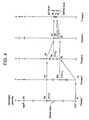
- Fig. 4 shows a pattern indicating a process for calculating an optimal value by repeating the processing from step S303 to step S308.
- the process for calculating an optimal value for the optimization parameter P includes processes 1 to 5. At the first time, initialization is performed, and the temperatures T estimated using the PM value are higher than the permissible temperatures T0. Therefore, process 2, the PM value is used as a new PH value, and the same processing is performed. Every time the processing from step S303 to step S308 is repeated, the difference ⁇ P between the variable PM and variable PL is halved. The domain within which an optimal value is present is gradually narrowed.
- step S310 the optimization parameter value P
- step S311 Control is then passed to step 211 in Fig. 2 .
- the temperatures of the X-ray tube 20 and high-voltage generator 10 to be attained during scanning are estimated. If the temperatures exceed the permissible temperatures, it means that the temperatures may cause overheat. In this case, an indication that scanning is disabled is displayed. Furthermore, when the optimizing means is selected, an optimization parameter that is a tube current or a tube voltage is optimized according to the binary search and set to a value that causes the temperatures to fall below the permissible temperatures. Therefore, the X-ray tube and high-voltage generator will not overheat but operate with the temperatures thereof retained below the permissible temperatures. Deterioration of the X-ray tube 20 or high-voltage generator 10 is prevented. Eventually, highly reliable scanning can be ensured.
- the temperatures of the X-ray tube 20 and high-voltage generator 10 are controlled.
- an accumulated quantity of heat or any other physical quantity relevant to heat dissipation may be adopted for control as well.
- the tube current of the X-ray tube is optimized.
- the tube voltage may be adopted as an optimization parameter.
- the cooling time required for the X-ray tube 20 may be adopted as the optimization parameter.
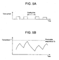
- the cooling time refers to a time during which no tube current flows as indicated in Figs. 5 .
- the temperature of the X-ray tube 20 rises or drops as indicated in Fig. 5(B) .
- the cooling time is set to a long time, the X-ray tube 20 is cooled so that the temperature of the X-ray tube 20 will be retained at the permissible temperature or lower. The longer the cooling time is, the lower the temperature is. Therefore, the steps S306 and S307 described in the flowchart of Fig. 3 are switched.
- optimization is performed using the binary search.
- an optimization parameter value may be determined or directly calculated as an inverse function of the function f or g. Otherwise, a high-order search may be adopted for fast search.
- the temperatures of the X-ray tube 20 and high-voltage generator 10 are estimated for optimization.
- the temperature of a data acquisition system (DAS) including the data acquisition unit 26 that is a heat dissipator may be estimated for optimization.
Landscapes
- Health & Medical Sciences (AREA)
- General Health & Medical Sciences (AREA)
- Toxicology (AREA)
- X-Ray Techniques (AREA)
- Apparatus For Radiation Diagnosis (AREA)
Claims (5)
- Röntgen-Bildgebungssystem, aufweisend:eine Röntgenröhre (20), die ein Röntgenstrahlungsbündel erzeugt;einen Hochspannungsgenerator (10), der Energie, die zur Erzeugung des Röntgenstrahlungsbündels erforderlich ist, an die Röntgenröhre (20) liefert;einen Röntgendetektor (24), der das Röntgenstrahlungsbündel detektiert;eine Datenerfassungsvorrichtung (26), die die Röntgenröhre (20) und den Röntgendetektor (24) steuert, die einander mit einem Gegenstand dazwischen gegenüberliegen, und die so Projektionsdaten bezüglich des Gegenstandes erfasst;eine Abschätzvorrichtung (60), um als eine Funktion von Steuerungsparametern der Röntgenröhre (20) und des Hochspannungsgenerators (10) sowohl von der Röntgenröhre (20) als auch dem Hochspannungsgenerator (10) während der Erfassung abgegebene Verlustwärmemengen abschätzen; undeine Steuerungsverarbeitungsvorrichtung (60), die die Steuerungsparameter der Röntgenröhre (20) und des Hochspannungsgenerators (10) auf der Basis der Schätzwerte der Wärmemengen optimiert, um somit eine Überhitzung der Röntgenröhre (20) und des Hochspannungsgenerators (10) zu verhindern.
- Röntgen-Bildgebungssystem nach Anspruch 1, wobei das Röntgen-Bildgebungssystem ein Röntgen-CT-System ist.
- Röntgen-Bildgebungssystem nach Anspruch 1 oder 2 mit einer Einrichtung in der Steuerungsverarbeitungsvorrichtung (60), um die Erfassung im Voraus zu verhindern, wenn die abgegebenen Verlustwärmemengen zulässige Wertebereiche der Überhitzung überschreiten.
- Röntgen-Bildgebungssystem nach Anspruch 1 oder 2 mit einer Einrichtung in der Steuerungsverarbeitungsvorrichtung (60) zum Durchführen der Optimierung bei einem der Erfassung vorausgehenden Schritt, wenn die abgegebenen Verlustwärmemengen die zulässigen Wertebereiche der Überhitzung überschreiten.
- Verfahren zum Verhindern der Überhitzung einer Röntgenvorrichtung mit den Schritten:Steuern einer Röntgenröhre (20) und eines Röntgendetektors (24), die einander mit einem Gegenstand dazwischen gegenüberliegen, um so Projektionsdaten bezüglich des Gegenstandes zu erfassen;Abschätzen sowohl von der Röntgenröhre (20) als auch einem Hochspannungsgenerator (10), der die Röntgenröhre (20) während der Erfassung mit Energie versorgt, abgegebener Verlustwärmemengen als eine Funktion von Steuerungsparametern der Röntgenröhre (20) und des Hochspannungsgenerators (10); undOptimieren der Steuerungsparameter der Röntgenröhre (20) und des Hochspannungsgenerators (10) auf der Basis der geschätzten Wärmemengen, um eine Überhitzung der Röntgenröhre (20) und des Hochspannungsgenerators (10) zu verhindern.
Applications Claiming Priority (2)
| Application Number | Priority Date | Filing Date | Title |
|---|---|---|---|
| JP2003350688A JP4262042B2 (ja) | 2003-10-09 | 2003-10-09 | 熱発生装置、x線撮像装置およびx線装置過熱防止方法 |
| JP2003350688 | 2003-10-09 |
Publications (3)
| Publication Number | Publication Date |
|---|---|
| EP1523227A2 EP1523227A2 (de) | 2005-04-13 |
| EP1523227A3 EP1523227A3 (de) | 2007-10-03 |
| EP1523227B1 true EP1523227B1 (de) | 2011-01-05 |
Family
ID=34309257
Family Applications (1)
| Application Number | Title | Priority Date | Filing Date |
|---|---|---|---|
| EP04256238A Expired - Lifetime EP1523227B1 (de) | 2003-10-09 | 2004-10-08 | Wärmeaufbau eines Generators, Röntgenbildgebungsystem und Verfahren zur Vermeidung der Überhitzung eines Röntgengeräts |
Country Status (5)
| Country | Link |
|---|---|
| US (1) | US7062016B2 (de) |
| EP (1) | EP1523227B1 (de) |
| JP (1) | JP4262042B2 (de) |
| CN (1) | CN100418479C (de) |
| DE (1) | DE602004030867D1 (de) |
Families Citing this family (21)
| Publication number | Priority date | Publication date | Assignee | Title |
|---|---|---|---|---|
| EP1627558A1 (de) * | 2003-05-16 | 2006-02-22 | Philips Intellectual Property & Standards GmbH | Verfahren und vorrichtung zur belichtung von röntgenbildern |
| ATE551660T1 (de) * | 2003-11-26 | 2012-04-15 | Koninkl Philips Electronics Nv | Optimierung des arbeitsablaufs für ein bilddarstellungsumfeld mit hohem durchsatz |
| JP4820060B2 (ja) * | 2004-02-27 | 2011-11-24 | ジーイー・メディカル・システムズ・グローバル・テクノロジー・カンパニー・エルエルシー | X線撮像装置およびx線撮像システム |
| CN101103923A (zh) * | 2006-07-14 | 2008-01-16 | Ge医疗系统环球技术有限公司 | X射线混合诊断系统 |
| US7512209B2 (en) * | 2006-09-14 | 2009-03-31 | General Electric Company | Thermal stabilization methods and apparatus |
| JP2008119094A (ja) * | 2006-11-09 | 2008-05-29 | Ge Medical Systems Global Technology Co Llc | X線管の駆動方法及びx線ct装置 |
| JP5184848B2 (ja) * | 2007-08-31 | 2013-04-17 | 株式会社東芝 | X線ct装置 |
| JP5063391B2 (ja) * | 2008-01-31 | 2012-10-31 | キヤノン株式会社 | 放射線画像撮影装置及びその駆動方法 |
| JP4693884B2 (ja) * | 2008-09-18 | 2011-06-01 | キヤノン株式会社 | マルチx線撮影装置及びその制御方法 |
| CN102158642B (zh) * | 2010-11-30 | 2013-05-08 | 深圳市蓝韵实业有限公司 | 一种通用的放射摄影系统时序控制装置 |
| DE102010062459B4 (de) | 2010-12-06 | 2018-08-02 | Siemens Healthcare Gmbh | Verfahren für ein Computertomographiegerät zur Reduzierung der Belastung einer Komponente, Rechenprogramm, Datenträger und Computertomographiegerät |
| CN103096608B (zh) * | 2011-10-31 | 2017-03-01 | Ge医疗系统环球技术有限公司 | 用于ct扫描架的冷却方法和冷却系统 |
| CN104027125A (zh) * | 2013-03-07 | 2014-09-10 | 上海西门子医疗器械有限公司 | 球管的状态信息指示方法、装置及x光成像设备 |
| CN105455829A (zh) * | 2014-08-04 | 2016-04-06 | 锐珂(上海)医疗器材有限公司 | 放射性射线照相技术中控制射线管的管电流的方法及相应的系统 |
| CN106137229A (zh) * | 2015-03-30 | 2016-11-23 | 上海西门子医疗器械有限公司 | 一种过热处理的方法、装置与x射线设备 |
| CN104970818A (zh) * | 2015-07-20 | 2015-10-14 | 上海圆工医疗设备有限公司 | 一种医用ct设备的远程监控系统 |
| JP7152209B2 (ja) * | 2017-07-20 | 2022-10-12 | キヤノンメディカルシステムズ株式会社 | X線ct装置 |
| US10722187B2 (en) * | 2018-08-31 | 2020-07-28 | General Electric Company | System and method for imaging a subject |
| CN109717885A (zh) * | 2018-12-30 | 2019-05-07 | 上海联影医疗科技有限公司 | 扫描模式选择方法、装置、医学成像设备和存储介质 |
| JP7381361B2 (ja) | 2020-02-14 | 2023-11-15 | キヤノンメディカルシステムズ株式会社 | X線ct装置 |
| CN118434362B (zh) * | 2021-12-23 | 2025-05-23 | 皇家飞利浦有限公司 | 动态成像系统工作流程优化 |
Family Cites Families (15)
| Publication number | Priority date | Publication date | Assignee | Title |
|---|---|---|---|---|
| US3842280A (en) * | 1970-12-23 | 1974-10-15 | Picker Corp | Protective circuit for limiting the input power applied to an x-ray tube and method of operation |
| US3770963A (en) * | 1971-11-01 | 1973-11-06 | Litton Medical Products | Dental x-ray monitoring system |
| US3974385A (en) * | 1972-12-06 | 1976-08-10 | Siemens Aktiengesellschaft | X-ray diagnostic apparatus |
| DE2345947C3 (de) * | 1973-09-12 | 1981-12-03 | Philips Patentverwaltung Gmbh, 2000 Hamburg | Schaltungsanordnung zur Überwachung der Belastung einer Röntgenröhre |
| US4386320A (en) * | 1978-09-15 | 1983-05-31 | Lafrance Robert R | X-Ray system signal derivation circuits for heat unit indicators and/or calibration meters |
| CA1151314A (en) * | 1978-09-15 | 1983-08-02 | Robert R. Lafrance | X-ray system signal derivation circuits for heat unit indicators and/or calibration meters |
| US4311913A (en) * | 1979-10-04 | 1982-01-19 | Picker Corporation | X-Ray tube current control |
| US4918714A (en) * | 1988-08-19 | 1990-04-17 | Varian Associates, Inc. | X-ray tube exposure monitor |
| US4991193A (en) * | 1988-11-25 | 1991-02-05 | Picker International, Inc. | System safety monitor for CT scanners |
| FR2646982B1 (fr) * | 1989-05-10 | 1992-02-07 | Gen Electric Cgr | Dispositif de securite pour ensemble radiogene |
| DE4217874A1 (de) * | 1992-05-29 | 1993-12-02 | Juergen Ziehm | Mobile chirurgische Röntgendiagnostikeinrichtung |
| CN1106571A (zh) * | 1994-02-05 | 1995-08-09 | 周仕涛 | X射线管 |
| US6487463B1 (en) * | 1998-06-08 | 2002-11-26 | Gateway, Inc. | Active cooling system for an electronic device |
| JP4460695B2 (ja) * | 1999-11-24 | 2010-05-12 | 株式会社東芝 | X線コンピュータ断層撮影装置 |
| JP4699585B2 (ja) | 2000-02-25 | 2011-06-15 | Geヘルスケア・ジャパン株式会社 | X線ct装置 |
-
2003
- 2003-10-09 JP JP2003350688A patent/JP4262042B2/ja not_active Expired - Fee Related
-
2004
- 2004-10-07 US US10/960,663 patent/US7062016B2/en not_active Expired - Fee Related
- 2004-10-08 DE DE602004030867T patent/DE602004030867D1/de not_active Expired - Lifetime
- 2004-10-08 EP EP04256238A patent/EP1523227B1/de not_active Expired - Lifetime
- 2004-10-09 CN CNB2004100921671A patent/CN100418479C/zh not_active Expired - Fee Related
Also Published As
| Publication number | Publication date |
|---|---|
| JP2005116396A (ja) | 2005-04-28 |
| US7062016B2 (en) | 2006-06-13 |
| EP1523227A3 (de) | 2007-10-03 |
| DE602004030867D1 (de) | 2011-02-17 |
| CN1605323A (zh) | 2005-04-13 |
| EP1523227A2 (de) | 2005-04-13 |
| JP4262042B2 (ja) | 2009-05-13 |
| CN100418479C (zh) | 2008-09-17 |
| US20050078795A1 (en) | 2005-04-14 |
Similar Documents
| Publication | Publication Date | Title |
|---|---|---|
| EP1523227B1 (de) | Wärmeaufbau eines Generators, Röntgenbildgebungsystem und Verfahren zur Vermeidung der Überhitzung eines Röntgengeräts | |
| US6744846B2 (en) | Method and apparatus for automatic exposure control in CT scanning | |
| KR100457607B1 (ko) | 단층 촬영 이미징 스캔 조건 결정 방법, 단층 촬영 이미징방법 및 x선 ct 장치 | |
| US7460635B2 (en) | X-ray CT apparatus, method of controlling the same, and program | |
| US11712216B2 (en) | Methods and systems for x-ray tube conditioning | |
| EP3777688B1 (de) | Konditionierung von röntgenröhren | |
| US8503615B2 (en) | Active thermal control of X-ray tubes | |
| JPWO2007138979A1 (ja) | X線ct装置 | |
| EP0998173B1 (de) | Tomografische Abtastseinrichtung | |
| EP4412530B1 (de) | Optimierung des arbeitsablaufs eines dynamischen abbildungssystems | |
| CN102415220A (zh) | 用于对x射线生成设备的焦斑进行负荷相关尺寸调整的方法和设备 | |
| CN110916696B (zh) | 扫描方法、装置及计算机断层扫描系统 | |
| US20060104496A1 (en) | Method and system for controlling an X-ray imaging system | |
| JP2011024642A (ja) | 半導体電力変換装置、及びこれを用いたx線高電圧装置、フィラメント加熱装置、x線ct装置、x線診断装置 | |
| JP2019018021A (ja) | X線ct装置 | |
| US20050147208A1 (en) | X-ray tube coolant volume control system | |
| US10531855B2 (en) | X-ray computed tomography apparatus | |
| JP4820060B2 (ja) | X線撮像装置およびx線撮像システム | |
| JP5049502B2 (ja) | X線コンピュータ断層撮影装置及びその制御方法 | |
| US20170092457A1 (en) | X-ray computed tomography imaging apparatus and x-ray tube apparatus | |
| JP2022046946A (ja) | X線ct装置 | |
| EP4201332A1 (de) | Optimierung des arbeitsablaufs eines dynamischen abbildungssystems | |
| JP2017074299A (ja) | 放射線断層撮影装置及びプログラム | |
| JPH05192323A (ja) | X線ct装置 | |
| JP3267548B2 (ja) | X線撮影装置 |
Legal Events
| Date | Code | Title | Description |
|---|---|---|---|
| PUAI | Public reference made under article 153(3) epc to a published international application that has entered the european phase |
Free format text: ORIGINAL CODE: 0009012 |
|
| AK | Designated contracting states |
Kind code of ref document: A2 Designated state(s): AT BE BG CH CY CZ DE DK EE ES FI FR GB GR HU IE IT LI LU MC NL PL PT RO SE SI SK TR |
|
| AX | Request for extension of the european patent |
Extension state: AL HR LT LV MK |
|
| PUAL | Search report despatched |
Free format text: ORIGINAL CODE: 0009013 |
|
| AK | Designated contracting states |
Kind code of ref document: A3 Designated state(s): AT BE BG CH CY CZ DE DK EE ES FI FR GB GR HU IE IT LI LU MC NL PL PT RO SE SI SK TR |
|
| AX | Request for extension of the european patent |
Extension state: AL HR LT LV MK |
|
| 17P | Request for examination filed |
Effective date: 20080403 |
|
| AKX | Designation fees paid |
Designated state(s): DE FR GB NL |
|
| 17Q | First examination report despatched |
Effective date: 20080521 |
|
| GRAP | Despatch of communication of intention to grant a patent |
Free format text: ORIGINAL CODE: EPIDOSNIGR1 |
|
| GRAS | Grant fee paid |
Free format text: ORIGINAL CODE: EPIDOSNIGR3 |
|
| GRAA | (expected) grant |
Free format text: ORIGINAL CODE: 0009210 |
|
| RAP1 | Party data changed (applicant data changed or rights of an application transferred) |
Owner name: GE MEDICAL SYSTEMS GLOBAL TECHNOLOGY COMPANY, LLC |
|
| AK | Designated contracting states |
Kind code of ref document: B1 Designated state(s): DE FR GB NL |
|
| REG | Reference to a national code |
Ref country code: GB Ref legal event code: FG4D |
|
| REF | Corresponds to: |
Ref document number: 602004030867 Country of ref document: DE Date of ref document: 20110217 Kind code of ref document: P |
|
| REG | Reference to a national code |
Ref country code: DE Ref legal event code: R096 Ref document number: 602004030867 Country of ref document: DE Effective date: 20110217 |
|
| REG | Reference to a national code |
Ref country code: NL Ref legal event code: T3 |
|
| PLBE | No opposition filed within time limit |
Free format text: ORIGINAL CODE: 0009261 |
|
| STAA | Information on the status of an ep patent application or granted ep patent |
Free format text: STATUS: NO OPPOSITION FILED WITHIN TIME LIMIT |
|
| 26N | No opposition filed |
Effective date: 20111006 |
|
| REG | Reference to a national code |
Ref country code: DE Ref legal event code: R097 Ref document number: 602004030867 Country of ref document: DE Effective date: 20111006 |
|
| GBPC | Gb: european patent ceased through non-payment of renewal fee |
Effective date: 20111008 |
|
| REG | Reference to a national code |
Ref country code: FR Ref legal event code: ST Effective date: 20120629 |
|
| PG25 | Lapsed in a contracting state [announced via postgrant information from national office to epo] |
Ref country code: FR Free format text: LAPSE BECAUSE OF NON-PAYMENT OF DUE FEES Effective date: 20111102 Ref country code: GB Free format text: LAPSE BECAUSE OF NON-PAYMENT OF DUE FEES Effective date: 20111008 |
|
| PGFP | Annual fee paid to national office [announced via postgrant information from national office to epo] |
Ref country code: DE Payment date: 20131029 Year of fee payment: 10 |
|
| PGFP | Annual fee paid to national office [announced via postgrant information from national office to epo] |
Ref country code: NL Payment date: 20131026 Year of fee payment: 10 |
|
| REG | Reference to a national code |
Ref country code: DE Ref legal event code: R119 Ref document number: 602004030867 Country of ref document: DE |
|
| REG | Reference to a national code |
Ref country code: NL Ref legal event code: V1 Effective date: 20150501 |
|
| PG25 | Lapsed in a contracting state [announced via postgrant information from national office to epo] |
Ref country code: DE Free format text: LAPSE BECAUSE OF NON-PAYMENT OF DUE FEES Effective date: 20150501 |
|
| PG25 | Lapsed in a contracting state [announced via postgrant information from national office to epo] |
Ref country code: NL Free format text: LAPSE BECAUSE OF NON-PAYMENT OF DUE FEES Effective date: 20150501 |