EP1522782B1 - Anordnung mit Anschlussarmatur und Wellschlauch - Google Patents
Anordnung mit Anschlussarmatur und Wellschlauch Download PDFInfo
- Publication number
- EP1522782B1 EP1522782B1 EP04254872A EP04254872A EP1522782B1 EP 1522782 B1 EP1522782 B1 EP 1522782B1 EP 04254872 A EP04254872 A EP 04254872A EP 04254872 A EP04254872 A EP 04254872A EP 1522782 B1 EP1522782 B1 EP 1522782B1
- Authority
- EP
- European Patent Office
- Prior art keywords
- pipe
- assembly
- fitting
- screw thread
- thread
- Prior art date
- Legal status (The legal status is an assumption and is not a legal conclusion. Google has not performed a legal analysis and makes no representation as to the accuracy of the status listed.)
- Expired - Lifetime
Links
- 239000000565 sealant Substances 0.000 claims description 2
- 230000008878 coupling Effects 0.000 description 8
- 238000010168 coupling process Methods 0.000 description 8
- 238000005859 coupling reaction Methods 0.000 description 8
- 238000009428 plumbing Methods 0.000 description 5
- 230000000712 assembly Effects 0.000 description 4
- 238000000429 assembly Methods 0.000 description 4
- 239000000463 material Substances 0.000 description 3
- 238000007789 sealing Methods 0.000 description 3
- 239000004033 plastic Substances 0.000 description 2
- 229920003023 plastic Polymers 0.000 description 2
- 239000002699 waste material Substances 0.000 description 2
- 239000004743 Polypropylene Substances 0.000 description 1
- 238000005336 cracking Methods 0.000 description 1
- 229920001971 elastomer Polymers 0.000 description 1
- 239000000806 elastomer Substances 0.000 description 1
- 239000003292 glue Substances 0.000 description 1
- 238000009434 installation Methods 0.000 description 1
- 230000004048 modification Effects 0.000 description 1
- 238000012986 modification Methods 0.000 description 1
- -1 polypropylene Polymers 0.000 description 1
- 229920001155 polypropylene Polymers 0.000 description 1
- 230000000717 retained effect Effects 0.000 description 1
- 230000003313 weakening effect Effects 0.000 description 1
Images


Classifications
-
- F—MECHANICAL ENGINEERING; LIGHTING; HEATING; WEAPONS; BLASTING
- F16—ENGINEERING ELEMENTS AND UNITS; GENERAL MEASURES FOR PRODUCING AND MAINTAINING EFFECTIVE FUNCTIONING OF MACHINES OR INSTALLATIONS; THERMAL INSULATION IN GENERAL
- F16L—PIPES; JOINTS OR FITTINGS FOR PIPES; SUPPORTS FOR PIPES, CABLES OR PROTECTIVE TUBING; MEANS FOR THERMAL INSULATION IN GENERAL
- F16L33/00—Arrangements for connecting hoses to rigid members; Rigid hose-connectors, i.e. single members engaging both hoses
- F16L33/24—Arrangements for connecting hoses to rigid members; Rigid hose-connectors, i.e. single members engaging both hoses with parts screwed directly on or into the hose
-
- F—MECHANICAL ENGINEERING; LIGHTING; HEATING; WEAPONS; BLASTING
- F16—ENGINEERING ELEMENTS AND UNITS; GENERAL MEASURES FOR PRODUCING AND MAINTAINING EFFECTIVE FUNCTIONING OF MACHINES OR INSTALLATIONS; THERMAL INSULATION IN GENERAL
- F16L—PIPES; JOINTS OR FITTINGS FOR PIPES; SUPPORTS FOR PIPES, CABLES OR PROTECTIVE TUBING; MEANS FOR THERMAL INSULATION IN GENERAL
- F16L25/00—Construction or details of pipe joints not provided for in, or of interest apart from, groups F16L13/00 - F16L23/00
- F16L25/0036—Joints for corrugated pipes
Definitions
- the present invention relates to a flexible pipe assembly comprising a flexible pipe and a pipe fitting for coupling to the flexible pipe as known for example from document DE-A-195 12 033 .
- the invention has particular utility as a plumbing fitting, for example as a waste pipe or vent pipe fitting.
- Waste pipe assemblies for basins, baths, sinks, urinals, WCs and the like are conventionally formed of conjoined rigid plastic sections.
- a plumber will typically identify the appropriate selection of couplings, bends and straight pipe sections, which may be cut to an appropriate length, to form the assembly, and these are then coupled mechanically or using appropriate glue.
- flexible pipes are also available and in a range of situations a flexible pipe section, provided with appropriate end fittings, may be fitted far more easily, and more quickly, that an assembly of conventional rigid fittings.
- Flexible plumbing pipe comes in a variety of forms, including pipe with a wave form or corrugated wall which may be flexed to create relatively shallow bends or curves.
- Other corrugated flexible pipe has a zigzag or v-shaped wall section which is more readily flexed, which may be axially extended or retracted, and which may be configured to retain deformation.
- a pipe fitting for coupling to a pipe having a corrugated wall
- the pipe fitting comprising a tubular body defining a screw thread for engaging a pipe wall and a cylindrical axially extending seal portion for forming an interference fit with the pipe wall.
- the screw thread allows the pipe fitting to be advanced into or over the end of the pipe simply by rotating the fitting relative to the pipe, and bringing the seal portion into sealing engagement with the pipe wall.
- the provision of the screw thread allows the interference fit between the seal portion and the pipe wall to be created manually, rather than requiring application of a two or three tonne axial force by an appropriate press, as is currently required.
- the screw thread is adapted to engage the inner wall of a pipe and the seal portion is adapted for engaging the inner wall of a pipe. Locating the thread and seal portion inside the pipe assists in supporting the pipe and in installation. If desired, elements of the fitting, or a separate collar or the like, may be adapted to extend over the exterior of the pipe, which may improve appearance.
- the fitting may thus also define an annulus in which the end of the pipe may be located, which annulus may accommodate a suitable sealant.
- the leading end of the screw thread is tapered or chamfered. This assists in providing an initial engagement between the thread and the pipe wall and in allowing the thread to travel along the pipe wall.
- the trailing end of the thread may be tapered or chamfered, to assist in removing the fitting from a pipe.
- the crest of the screw thread is radiused, to avoid damaging or weakening the pipe.
- the radius is relatively small, such that the thread will still bite into the pipe wall.
- the thread has a lead angle greater than the back angle.
- the lead angle is in the region of 35° and the back angle is 6°; other angles may of course be used.
- One or more fittings may be provided in combination with a length of flexible pipe.
- the pipe is preferably of variable length, that is the pipe may be extended or retracted. This offers the significant advantage of allowing a length of pipe provided in combination with one or two fittings to be fitted relatively easily into an existing plumbing system, or some other form of pipe work, without requiring dismantling or disassembly of the existing system.
- the thread root diameter is sized to avoid contact with the pipe wall, so reducing friction between the fitting and the pipe.
- the fitting may be formed of any appropriate material, including polymeric materials such as polypropylene, uPVC and ABS, or may be metallic.
- the fitting may be provided in combination with an operator grip adapted to engage with the fitting and facilitate rotation of the fitting relative to the pipe.
- a grip may be particularly convenient for use in combination with fittings which are difficult to grip.
- the fitting may include a shoulder to abut the end of the pipe, and a seal may be provided between the shoulder and the pipe end. Where a collar is present, the collar may be arranged to abut the shoulder.
- FIGS 1a and 1b of the drawings illustrate a pipe fitting 10 in accordance with a preferred embodiment of the present invention.
- the fitting 10 is intended to engage with the end of a length of flexible pipe (not shown) of the type disclosed, for example, in US Patent Nos 4,846,510 and 4,927,191 , and UK Patent 2,298,470 .
- the pipe is flexible, in that it may be flexed to create up to 180° bends, and may also be axially extended or contracted.
- the pipe wall is also configured such that deformation of the pipe tends to be retained.
- the fitting 10 is intended for coupling to the end of a flexible pipe defining a minimum internal diameter of 38 mm, this minimum diameter being defined by the roots of the pipe wall corrugations.
- the fitting 10 comprises a hollow tubular body 12 and has a leading end defining a screw thread 14 for engaging with an inner wall of a pipe.
- the screw thread is followed by a cylindrical seal portion 16, which is followed by a 50 mm diameter cylindrical coupling portion 18.
- the screw thread 14 comprises a tapering nose portion 20 intended to facilitate location of the fitting within the pipe.
- the screw thread itself has a 5 mm pitch and has a root diameter less than the 38mm minimum internal diameter defined by the pipe corrugations.
- the maximum external diameter defined by the thread is 41.4 mm, the thread diameter being reduced towards the start and end of the thread to facilitate initial engagement of the thread of the pipe wall and to facilitate removal of the fitting from the pipe. That is, the start and end of the thread are 'blended' or tapered into the seal portion,
- the lead angle of the thread is 35° and the back angle is 6°.
- the fitting 10 has been moulded from plastics material and the mould is such that there are no sharp corners present on the screw thread 14, a small radius being used to break the thread crest.
- the presence of the various small radii assists in avoiding problems such as stress or cracking of the fitting 10, and also avoids damage to the flexible pipe by contact with the screw thread 14.
- the effectiveness of the fitting 10 is enhanced if the radius on the crest of the screw thread 14 is relatively small, allowing the thread to bite into the wall of the flexible pipe.
- the seal portion 16 follows directly after the screw thread 14 and in this example has an external diameter of 38.9 mm, that is 0.9 mm greater than the 38 mm internal diameter of the flexible pipe. Thus, the seal portion 16 will form an interference fit with the pipe.
- the seal portion 16 ends in a shoulder 17 which in use may abut the end of the pipe.
- a further seal such as an elastomer seal or the like, may be provided on the shoulder 17.
- the coupling portion 18 is intended for coupling to conventional 50 mm plumbing pipes or fittings.
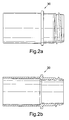
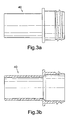
- Figures 2a, 2b , 3a and 3b of the drawings are views of fittings 30, 40 of generally similar configuration to the fitting 10, but intended for coupling between flexible pipe and conventional fittings or pipe of 40 mm diameter and 32 mm diameter, respectively.
- FIG. 4 this shows a length of flexible pipe 50 over which a finishing collar 52 is first fitted, the collar 52 serving to provide the finished assembly with a more attractive appearance.
- a first pipe fitting 54 is then screwed into the end of the pipe 50.
- the fitting screw thread 56 engages with the inner wall of the pipe and as the fitting 54 is rotated relative to the pipe 50, the screw thread 56 pulls the following seal portion 58 into the pipe 50 to create an interference fit with the pipe 50 and the seal portion 58.
- a user grip 60 is provided and may be engaged with the fitting 54 to allow a user to apply the necessary torque to the fitting 54.
- the pipe 50 may be cut to the appropriate length, as illustrated in Figure 6 .
- a second collar 62 is then located on the cut end of the pipe 50, as illustrated in Figure 7 , and the second fitting 64 screwed into the cut end of the pipe, as illustrated in Figure 8 .
- an inlet seal 66 is then located in the free end of the first fitting 54 (see Figure 9 ).
Landscapes
- Engineering & Computer Science (AREA)
- General Engineering & Computer Science (AREA)
- Mechanical Engineering (AREA)
- Joints That Cut Off Fluids, And Hose Joints (AREA)
Claims (14)
- Flexible Rohrbaugruppe, die Folgendes umfasst:ein flexibles Rohr (50), das eine gewellte Wand hat und einen minimalen Innendurchmesser definiert, undeinen Rohranschluss (10), der einen röhrenförmigen Korpus, der ein Schraubengewinde (14) zum Ineingriffnehmen einer Innenfläche der Rohrwand und einen sich in Axialrichtung erstreckenden Dichtungsabschnitt (16) zum Bilden einer Presspassung mit der Innenfläche der Rohrwand umfasst, wobei, bei Anwendung, eine Dichtung zwischen dem Dichtungsabschnitt und der Rohrwand gebildet wird,dadurch gekennzeichnet, dass der sich in Axialrichtung erstreckende Dichtungsabschnitt (14) zylindrisch ist und einen Durchmesser hat, der größer ist als der minimale Innendurchmesser des Rohres und der geringer ist als der maximale Durchmesser des Schraubengewindes und größer als der Durchmesser des Schraubengewindefußes.
- Baugruppe nach einem der vorhergehenden Ansprüche, die einen Abschnitt (52) umfasst, der dafür eingerichtet ist, sich über das Äußere des Rohres (50) zu erstrecken.
- Baugruppe nach Anspruch 2, wobei der röhrenförmige Korpus und der Abschnitt (52) einen Ringspalt zum Aufnehmen eines Endes eines Rohres bilden.
- Baugruppe nach Anspruch 3, wobei der Ringspalt dafür eingerichtet ist, eine geeignete Dichtungsmasse aufzunehmen.
- Baugruppe nach einem der vorhergehenden Ansprüche, wobei ein vorderes Ende des Schraubengewindes (14) verjüngt ist.
- Baugruppe nach einem der vorhergehenden Ansprüche, wobei ein hinteres Ende des Schraubengewindes (14) verjüngt ist.
- Baugruppe nach einem der vorhergehenden Ansprüche, wobei das Schraubengewinde (14) einen gerundeten Scheitel hat.
- Baugruppe nach einem der vorhergehenden Ansprüche, wobei das Schraubengewinde (14) einen Anschnittwinkel hat, der größer ist als der Rückenwinkel.
- Baugruppe nach Anspruch 8, wobei der Anschnittwinkel in dem Bereich von 35° liegt und der Rückenwinkel 6° beträgt.
- Baugruppe nach einem der vorhergehenden Ansprüche, wobei das Rohr (50) eine veränderliche Länge hat.
- Baugruppe nach einem der vorhergehenden Ansprüche, wobei der Durchmesser des Schraubengewindefußes dafür bemessen ist, eine Berührung mit der Rohrwand zu vermeiden.
- Baugruppe nach einem der vorhergehenden Ansprüche, in Kombination mit einem Bedienergriff, der dafür eingerichtet ist, mit dem Anschluss (10) ineinanderzugreifen und eine Drehung des Anschlusses im Verhältnis zu dem Rohr zu erleichtern.
- Baugruppe nach einem der vorhergehenden Ansprüche, die einen Absatz (17) einschließt, der dafür eingerichtet ist, an ein Ende des Rohres anzustoßen.
- Baugruppe nach Anspruch 13, die ferner ein Dichtungselement zum Anordnen zwischen dem Absatz (17) und dem Rohrende einschließt.
Priority Applications (1)
| Application Number | Priority Date | Filing Date | Title |
|---|---|---|---|
| PL04254872T PL1522782T3 (pl) | 2003-08-14 | 2004-08-13 | Zestaw z łącznikiem rurowym i elastyczną rurą falistą |
Applications Claiming Priority (2)
| Application Number | Priority Date | Filing Date | Title |
|---|---|---|---|
| GB0319064 | 2003-08-14 | ||
| GBGB0319064.2A GB0319064D0 (en) | 2003-08-14 | 2003-08-14 | Pipe fittings |
Publications (2)
| Publication Number | Publication Date |
|---|---|
| EP1522782A1 EP1522782A1 (de) | 2005-04-13 |
| EP1522782B1 true EP1522782B1 (de) | 2013-04-03 |
Family
ID=28052476
Family Applications (1)
| Application Number | Title | Priority Date | Filing Date |
|---|---|---|---|
| EP04254872A Expired - Lifetime EP1522782B1 (de) | 2003-08-14 | 2004-08-13 | Anordnung mit Anschlussarmatur und Wellschlauch |
Country Status (3)
| Country | Link |
|---|---|
| EP (1) | EP1522782B1 (de) |
| GB (1) | GB0319064D0 (de) |
| PL (1) | PL1522782T3 (de) |
Families Citing this family (1)
| Publication number | Priority date | Publication date | Assignee | Title |
|---|---|---|---|---|
| DE202006014736U1 (de) * | 2006-09-26 | 2007-11-08 | CKW Gesellschaft für Kunststoffverarbeitung mbH | Rohrverbindung für Abwasserleitungen in Caravanen, Campingmobilen o.dgl. |
Family Cites Families (3)
| Publication number | Priority date | Publication date | Assignee | Title |
|---|---|---|---|---|
| GB847721A (en) * | 1958-05-21 | 1960-09-14 | Superflexit | Improvements in end fittings for flexible hoses, conduits and the like |
| DE19512033A1 (de) * | 1995-03-31 | 1996-10-10 | Tecalemit Gmbh Deutsche | Anschlußarmatur für wellförmig ausgeführte Sicherheitsrohr- und Schlauchleitungen aus thermoplastischen Kunststoffen |
| DE19602887C1 (de) * | 1996-01-29 | 1997-06-12 | Dieter Geiss | Verfahren und Bausatz zum Herstellen einer Leitungsverbindung |
-
2003
- 2003-08-14 GB GBGB0319064.2A patent/GB0319064D0/en not_active Ceased
-
2004
- 2004-08-13 EP EP04254872A patent/EP1522782B1/de not_active Expired - Lifetime
- 2004-08-13 PL PL04254872T patent/PL1522782T3/pl unknown
Also Published As
| Publication number | Publication date |
|---|---|
| EP1522782A1 (de) | 2005-04-13 |
| GB0319064D0 (en) | 2003-09-17 |
| PL1522782T3 (pl) | 2013-09-30 |
Similar Documents
| Publication | Publication Date | Title |
|---|---|---|
| US8752867B2 (en) | Sanitary hose coupling | |
| JP2524611B2 (ja) | コルゲ−トパイプ用プラスチック管継手 | |
| US4805933A (en) | Hose end sleeve | |
| EP1386107B1 (de) | Rohrkupplung | |
| EP3290182B1 (de) | Rohrherstellungsvorrichtung und rohrherstellungsverfahren für spiralrohr | |
| US20070257448A1 (en) | Snap in place gasket for sealing plastic pipelines and method of installation | |
| US6499772B1 (en) | Radial conduit coupling system and method | |
| EP3612761B1 (de) | Koppler | |
| EP1162399A3 (de) | Schlauchkupplung für Kraftfahrzeuge | |
| DE102004025067A1 (de) | Rohrverbindung | |
| EP0302061B1 (de) | Leitung zur wiederbeschichtung von unterirdischen leitungen | |
| EP1522782B1 (de) | Anordnung mit Anschlussarmatur und Wellschlauch | |
| US10184601B2 (en) | Coupling assembly for connecting a drain to a drain pipe | |
| US4400021A (en) | Reusable type hose end fitting | |
| EP2459810B1 (de) | Anschlussvorrichtung für toilettenschüssel | |
| JP2011069484A (ja) | ホース継手 | |
| US5692416A (en) | Shower head supply pipe tool | |
| JP2001263557A (ja) | 合成樹脂管および管路 | |
| EP1907744B1 (de) | Kupplung zwischen zwei rohren mit getrennten einstellklemmen | |
| WO2008107653A1 (en) | Method of applying and forming sealant | |
| JP3605688B2 (ja) | 管体の連結方法及び連結構造 | |
| CN209819034U (zh) | 一种后收紧型自粘防水套管 | |
| JP3508093B2 (ja) | ホ−ス接続具 | |
| US4258942A (en) | Threaded ferrule hose coupling | |
| WO2014207431A1 (en) | A pipe coupling |
Legal Events
| Date | Code | Title | Description |
|---|---|---|---|
| PUAI | Public reference made under article 153(3) epc to a published international application that has entered the european phase |
Free format text: ORIGINAL CODE: 0009012 |
|
| AK | Designated contracting states |
Kind code of ref document: A1 Designated state(s): AT BE BG CH CY CZ DE DK EE ES FI FR GB GR HU IE IT LI LU MC NL PL PT RO SE SI SK TR |
|
| AX | Request for extension of the european patent |
Extension state: AL HR LT LV MK |
|
| 17P | Request for examination filed |
Effective date: 20050929 |
|
| AKX | Designation fees paid |
Designated state(s): AT BE BG CH CY CZ DE DK EE ES FI FR GB GR HU IE IT LI LU MC NL PL PT RO SE SI SK TR |
|
| GRAP | Despatch of communication of intention to grant a patent |
Free format text: ORIGINAL CODE: EPIDOSNIGR1 |
|
| GRAS | Grant fee paid |
Free format text: ORIGINAL CODE: EPIDOSNIGR3 |
|
| GRAA | (expected) grant |
Free format text: ORIGINAL CODE: 0009210 |
|
| AK | Designated contracting states |
Kind code of ref document: B1 Designated state(s): AT BE BG CH CY CZ DE DK EE ES FI FR GB GR HU IE IT LI LU MC NL PL PT RO SE SI SK TR |
|
| REG | Reference to a national code |
Ref country code: GB Ref legal event code: FG4D |
|
| REG | Reference to a national code |
Ref country code: CH Ref legal event code: EP Ref country code: AT Ref legal event code: REF Ref document number: 604966 Country of ref document: AT Kind code of ref document: T Effective date: 20130415 |
|
| REG | Reference to a national code |
Ref country code: IE Ref legal event code: FG4D |
|
| REG | Reference to a national code |
Ref country code: DE Ref legal event code: R096 Ref document number: 602004041559 Country of ref document: DE Effective date: 20130529 |
|
| REG | Reference to a national code |
Ref country code: AT Ref legal event code: MK05 Ref document number: 604966 Country of ref document: AT Kind code of ref document: T Effective date: 20130403 |
|
| PG25 | Lapsed in a contracting state [announced via postgrant information from national office to epo] |
Ref country code: SI Free format text: LAPSE BECAUSE OF FAILURE TO SUBMIT A TRANSLATION OF THE DESCRIPTION OR TO PAY THE FEE WITHIN THE PRESCRIBED TIME-LIMIT Effective date: 20130403 |
|
| REG | Reference to a national code |
Ref country code: NL Ref legal event code: VDEP Effective date: 20130403 |
|
| REG | Reference to a national code |
Ref country code: PL Ref legal event code: T3 |
|
| PG25 | Lapsed in a contracting state [announced via postgrant information from national office to epo] |
Ref country code: ES Free format text: LAPSE BECAUSE OF FAILURE TO SUBMIT A TRANSLATION OF THE DESCRIPTION OR TO PAY THE FEE WITHIN THE PRESCRIBED TIME-LIMIT Effective date: 20130714 Ref country code: AT Free format text: LAPSE BECAUSE OF FAILURE TO SUBMIT A TRANSLATION OF THE DESCRIPTION OR TO PAY THE FEE WITHIN THE PRESCRIBED TIME-LIMIT Effective date: 20130403 Ref country code: SE Free format text: LAPSE BECAUSE OF FAILURE TO SUBMIT A TRANSLATION OF THE DESCRIPTION OR TO PAY THE FEE WITHIN THE PRESCRIBED TIME-LIMIT Effective date: 20130403 Ref country code: FI Free format text: LAPSE BECAUSE OF FAILURE TO SUBMIT A TRANSLATION OF THE DESCRIPTION OR TO PAY THE FEE WITHIN THE PRESCRIBED TIME-LIMIT Effective date: 20130403 Ref country code: BE Free format text: LAPSE BECAUSE OF FAILURE TO SUBMIT A TRANSLATION OF THE DESCRIPTION OR TO PAY THE FEE WITHIN THE PRESCRIBED TIME-LIMIT Effective date: 20130403 Ref country code: GR Free format text: LAPSE BECAUSE OF FAILURE TO SUBMIT A TRANSLATION OF THE DESCRIPTION OR TO PAY THE FEE WITHIN THE PRESCRIBED TIME-LIMIT Effective date: 20130704 Ref country code: PT Free format text: LAPSE BECAUSE OF FAILURE TO SUBMIT A TRANSLATION OF THE DESCRIPTION OR TO PAY THE FEE WITHIN THE PRESCRIBED TIME-LIMIT Effective date: 20130805 Ref country code: NL Free format text: LAPSE BECAUSE OF FAILURE TO SUBMIT A TRANSLATION OF THE DESCRIPTION OR TO PAY THE FEE WITHIN THE PRESCRIBED TIME-LIMIT Effective date: 20130403 |
|
| PG25 | Lapsed in a contracting state [announced via postgrant information from national office to epo] |
Ref country code: CY Free format text: LAPSE BECAUSE OF FAILURE TO SUBMIT A TRANSLATION OF THE DESCRIPTION OR TO PAY THE FEE WITHIN THE PRESCRIBED TIME-LIMIT Effective date: 20130403 Ref country code: BG Free format text: LAPSE BECAUSE OF FAILURE TO SUBMIT A TRANSLATION OF THE DESCRIPTION OR TO PAY THE FEE WITHIN THE PRESCRIBED TIME-LIMIT Effective date: 20130703 |
|
| PG25 | Lapsed in a contracting state [announced via postgrant information from national office to epo] |
Ref country code: DK Free format text: LAPSE BECAUSE OF FAILURE TO SUBMIT A TRANSLATION OF THE DESCRIPTION OR TO PAY THE FEE WITHIN THE PRESCRIBED TIME-LIMIT Effective date: 20130403 Ref country code: SK Free format text: LAPSE BECAUSE OF FAILURE TO SUBMIT A TRANSLATION OF THE DESCRIPTION OR TO PAY THE FEE WITHIN THE PRESCRIBED TIME-LIMIT Effective date: 20130403 Ref country code: CZ Free format text: LAPSE BECAUSE OF FAILURE TO SUBMIT A TRANSLATION OF THE DESCRIPTION OR TO PAY THE FEE WITHIN THE PRESCRIBED TIME-LIMIT Effective date: 20130403 Ref country code: EE Free format text: LAPSE BECAUSE OF FAILURE TO SUBMIT A TRANSLATION OF THE DESCRIPTION OR TO PAY THE FEE WITHIN THE PRESCRIBED TIME-LIMIT Effective date: 20130403 |
|
| PLBE | No opposition filed within time limit |
Free format text: ORIGINAL CODE: 0009261 |
|
| STAA | Information on the status of an ep patent application or granted ep patent |
Free format text: STATUS: NO OPPOSITION FILED WITHIN TIME LIMIT |
|
| PG25 | Lapsed in a contracting state [announced via postgrant information from national office to epo] |
Ref country code: RO Free format text: LAPSE BECAUSE OF FAILURE TO SUBMIT A TRANSLATION OF THE DESCRIPTION OR TO PAY THE FEE WITHIN THE PRESCRIBED TIME-LIMIT Effective date: 20130403 Ref country code: IT Free format text: LAPSE BECAUSE OF FAILURE TO SUBMIT A TRANSLATION OF THE DESCRIPTION OR TO PAY THE FEE WITHIN THE PRESCRIBED TIME-LIMIT Effective date: 20130403 |
|
| REG | Reference to a national code |
Ref country code: DE Ref legal event code: R119 Ref document number: 602004041559 Country of ref document: DE |
|
| 26N | No opposition filed |
Effective date: 20140106 |
|
| REG | Reference to a national code |
Ref country code: CH Ref legal event code: PL |
|
| REG | Reference to a national code |
Ref country code: DE Ref legal event code: R097 Ref document number: 602004041559 Country of ref document: DE Effective date: 20140106 |
|
| PG25 | Lapsed in a contracting state [announced via postgrant information from national office to epo] |
Ref country code: DE Free format text: LAPSE BECAUSE OF NON-PAYMENT OF DUE FEES Effective date: 20140301 Ref country code: CH Free format text: LAPSE BECAUSE OF NON-PAYMENT OF DUE FEES Effective date: 20130831 Ref country code: MC Free format text: LAPSE BECAUSE OF FAILURE TO SUBMIT A TRANSLATION OF THE DESCRIPTION OR TO PAY THE FEE WITHIN THE PRESCRIBED TIME-LIMIT Effective date: 20130403 Ref country code: LI Free format text: LAPSE BECAUSE OF NON-PAYMENT OF DUE FEES Effective date: 20130831 |
|
| REG | Reference to a national code |
Ref country code: IE Ref legal event code: MM4A |
|
| REG | Reference to a national code |
Ref country code: FR Ref legal event code: ST Effective date: 20140430 |
|
| REG | Reference to a national code |
Ref country code: DE Ref legal event code: R119 Ref document number: 602004041559 Country of ref document: DE Effective date: 20140301 |
|
| PG25 | Lapsed in a contracting state [announced via postgrant information from national office to epo] |
Ref country code: IE Free format text: LAPSE BECAUSE OF NON-PAYMENT OF DUE FEES Effective date: 20130813 |
|
| PG25 | Lapsed in a contracting state [announced via postgrant information from national office to epo] |
Ref country code: FR Free format text: LAPSE BECAUSE OF NON-PAYMENT OF DUE FEES Effective date: 20130902 |
|
| PG25 | Lapsed in a contracting state [announced via postgrant information from national office to epo] |
Ref country code: TR Free format text: LAPSE BECAUSE OF FAILURE TO SUBMIT A TRANSLATION OF THE DESCRIPTION OR TO PAY THE FEE WITHIN THE PRESCRIBED TIME-LIMIT Effective date: 20130403 |
|
| PG25 | Lapsed in a contracting state [announced via postgrant information from national office to epo] |
Ref country code: HU Free format text: LAPSE BECAUSE OF FAILURE TO SUBMIT A TRANSLATION OF THE DESCRIPTION OR TO PAY THE FEE WITHIN THE PRESCRIBED TIME-LIMIT; INVALID AB INITIO Effective date: 20040813 Ref country code: LU Free format text: LAPSE BECAUSE OF NON-PAYMENT OF DUE FEES Effective date: 20130813 |
|
| PGFP | Annual fee paid to national office [announced via postgrant information from national office to epo] |
Ref country code: GB Payment date: 20170724 Year of fee payment: 14 |
|
| GBPC | Gb: european patent ceased through non-payment of renewal fee |
Effective date: 20180813 |
|
| PG25 | Lapsed in a contracting state [announced via postgrant information from national office to epo] |
Ref country code: GB Free format text: LAPSE BECAUSE OF NON-PAYMENT OF DUE FEES Effective date: 20180813 |
|
| PGFP | Annual fee paid to national office [announced via postgrant information from national office to epo] |
Ref country code: PL Payment date: 20210624 Year of fee payment: 18 |
|
| PG25 | Lapsed in a contracting state [announced via postgrant information from national office to epo] |
Ref country code: PL Free format text: LAPSE BECAUSE OF NON-PAYMENT OF DUE FEES Effective date: 20220813 |