EP1522767A2 - Formschlüssige Kupplung für Verteilergetriebe und Ausgleichsgetriebe für Kraftfahrzeuge - Google Patents
Formschlüssige Kupplung für Verteilergetriebe und Ausgleichsgetriebe für Kraftfahrzeuge Download PDFInfo
- Publication number
- EP1522767A2 EP1522767A2 EP04017590A EP04017590A EP1522767A2 EP 1522767 A2 EP1522767 A2 EP 1522767A2 EP 04017590 A EP04017590 A EP 04017590A EP 04017590 A EP04017590 A EP 04017590A EP 1522767 A2 EP1522767 A2 EP 1522767A2
- Authority
- EP
- European Patent Office
- Prior art keywords
- coupling
- lock
- double
- positive
- drive train
- Prior art date
- Legal status (The legal status is an assumption and is not a legal conclusion. Google has not performed a legal analysis and makes no representation as to the accuracy of the status listed.)
- Granted
Links
Images
Classifications
-
- F—MECHANICAL ENGINEERING; LIGHTING; HEATING; WEAPONS; BLASTING
- F16—ENGINEERING ELEMENTS AND UNITS; GENERAL MEASURES FOR PRODUCING AND MAINTAINING EFFECTIVE FUNCTIONING OF MACHINES OR INSTALLATIONS; THERMAL INSULATION IN GENERAL
- F16D—COUPLINGS FOR TRANSMITTING ROTATION; CLUTCHES; BRAKES
- F16D25/00—Fluid-actuated clutches
- F16D25/08—Fluid-actuated clutches with fluid-actuated member not rotating with a clutching member
- F16D25/088—Fluid-actuated clutches with fluid-actuated member not rotating with a clutching member the line of action of the fluid-actuated members being distinctly separate from the axis of rotation
-
- F—MECHANICAL ENGINEERING; LIGHTING; HEATING; WEAPONS; BLASTING
- F16—ENGINEERING ELEMENTS AND UNITS; GENERAL MEASURES FOR PRODUCING AND MAINTAINING EFFECTIVE FUNCTIONING OF MACHINES OR INSTALLATIONS; THERMAL INSULATION IN GENERAL
- F16D—COUPLINGS FOR TRANSMITTING ROTATION; CLUTCHES; BRAKES
- F16D11/00—Clutches in which the members have interengaging parts
- F16D11/08—Clutches in which the members have interengaging parts actuated by moving a non-rotating part axially
- F16D11/10—Clutches in which the members have interengaging parts actuated by moving a non-rotating part axially with clutching members movable only axially
-
- F—MECHANICAL ENGINEERING; LIGHTING; HEATING; WEAPONS; BLASTING
- F16—ENGINEERING ELEMENTS AND UNITS; GENERAL MEASURES FOR PRODUCING AND MAINTAINING EFFECTIVE FUNCTIONING OF MACHINES OR INSTALLATIONS; THERMAL INSULATION IN GENERAL
- F16D—COUPLINGS FOR TRANSMITTING ROTATION; CLUTCHES; BRAKES
- F16D25/00—Fluid-actuated clutches
- F16D25/08—Fluid-actuated clutches with fluid-actuated member not rotating with a clutching member
-
- F—MECHANICAL ENGINEERING; LIGHTING; HEATING; WEAPONS; BLASTING
- F16—ENGINEERING ELEMENTS AND UNITS; GENERAL MEASURES FOR PRODUCING AND MAINTAINING EFFECTIVE FUNCTIONING OF MACHINES OR INSTALLATIONS; THERMAL INSULATION IN GENERAL
- F16H—GEARING
- F16H61/00—Control functions within control units of change-speed- or reversing-gearings for conveying rotary motion ; Control of exclusively fluid gearing, friction gearing, gearings with endless flexible members or other particular types of gearing
- F16H61/26—Generation or transmission of movements for final actuating mechanisms
- F16H61/28—Generation or transmission of movements for final actuating mechanisms with at least one movement of the final actuating mechanism being caused by a non-mechanical force, e.g. power-assisted
- F16H61/30—Hydraulic or pneumatic motors or related fluid control means therefor
-
- B—PERFORMING OPERATIONS; TRANSPORTING
- B60—VEHICLES IN GENERAL
- B60K—ARRANGEMENT OR MOUNTING OF PROPULSION UNITS OR OF TRANSMISSIONS IN VEHICLES; ARRANGEMENT OR MOUNTING OF PLURAL DIVERSE PRIME-MOVERS IN VEHICLES; AUXILIARY DRIVES FOR VEHICLES; INSTRUMENTATION OR DASHBOARDS FOR VEHICLES; ARRANGEMENTS IN CONNECTION WITH COOLING, AIR INTAKE, GAS EXHAUST OR FUEL SUPPLY OF PROPULSION UNITS IN VEHICLES
- B60K17/00—Arrangement or mounting of transmissions in vehicles
- B60K17/34—Arrangement or mounting of transmissions in vehicles for driving both front and rear wheels, e.g. four wheel drive vehicles
- B60K17/348—Arrangement or mounting of transmissions in vehicles for driving both front and rear wheels, e.g. four wheel drive vehicles having differential means for driving one set of wheels, e.g. the front, at one speed and the other set, e.g. the rear, at a different speed
- B60K17/35—Arrangement or mounting of transmissions in vehicles for driving both front and rear wheels, e.g. four wheel drive vehicles having differential means for driving one set of wheels, e.g. the front, at one speed and the other set, e.g. the rear, at a different speed including arrangements for suppressing or influencing the power transfer, e.g. viscous clutches
- B60K17/3505—Arrangement or mounting of transmissions in vehicles for driving both front and rear wheels, e.g. four wheel drive vehicles having differential means for driving one set of wheels, e.g. the front, at one speed and the other set, e.g. the rear, at a different speed including arrangements for suppressing or influencing the power transfer, e.g. viscous clutches with self-actuated means, e.g. by difference of speed
-
- F—MECHANICAL ENGINEERING; LIGHTING; HEATING; WEAPONS; BLASTING
- F16—ENGINEERING ELEMENTS AND UNITS; GENERAL MEASURES FOR PRODUCING AND MAINTAINING EFFECTIVE FUNCTIONING OF MACHINES OR INSTALLATIONS; THERMAL INSULATION IN GENERAL
- F16H—GEARING
- F16H48/00—Differential gearings
- F16H48/20—Arrangements for suppressing or influencing the differential action, e.g. locking devices
- F16H48/24—Arrangements for suppressing or influencing the differential action, e.g. locking devices using positive clutches or brakes
Definitions
- the present invention relates to a form-locking Clutch for transfer case and differential of Motor vehicles according to the preamble of the claim 1, with an axially displaceable by an actuator Coupling part and with an acting on the actuator Control unit, wherein the driven coupling part is drivingly connected to a first wheel drive train and wherein the driving coupling part with the main drive train and with a second wheel drive train in Connection stands.
- the engaging member used in this known coupling is a cylinder with a piston rod and a Piston, whose one side is acted upon by a pressurized fluid while the other side of the mentioned spring is charged.
- These thresholds are at those speed differences, where the positive coupling parts still good can be brought into engagement.
- the drive shaft is mounted a front axle drive shaft, the via a universal joint drives a front axle, this being Front axle drive shaft to the first wheel drive train belongs.
- the drive shaft is also via another universal joint connected to the second wheel drive train, too the rear axle belongs, the latter being permanently driven becomes.
- the first wheel drive train will only then powered when the positive coupling, the is designed here as a dog clutch, is engaged.
- the effect the spring for loading the Ein Weggliedes for releasing the lock by the second loading direction replaced a double-acting element.
- the double-acting element is a through a fluid acted upon actuating cylinder.
- This counterforce is due to the choice of the piston diameter when actuated by a pressure medium accordingly adaptable to the requirements of the claw geometry (undercut), or is by variation of the back pressure means for example, a valve during operation as well Functional parameters of this force changeable.
- the counterforce either applied directly to the lock or by two separate actuators different Design type.
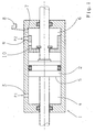
- the single figure shows an actuator for the distribution and differential gear shown in EP 0 510 457 B1, which hereby be completely encompassed should.
- the actuator consists of a double acting hydraulic cylinder 1, in which a piston. 2 is slidably mounted. Should the lock in the closing direction be actuated, pressure via a pressure feed 3 passed into a first piston chamber 4, whereby this pressure acts on the piston surface 5.
- the piston chamber 6 remains up vented to a defined piston travel, since the piston chamber 6 via a line 7 with a pressure medium reservoir. 8 connected is.
- the pressure in the piston chamber 4 at the beginning of Movement predominates, since the piston chamber 6 via the line. 7 is connected to the pressure medium reservoir 8.
- the spool 10 closes the line 7 and opens the pressure supply 9, whereby the Room 6 is also pressurized. Because the lock is in the closed state, the pressure in Piston chamber 4 reduces and with applied torque the Lock held closed. If the torque falls below a defined level, so outweighs the force from the pressure of the piston chamber 6, causing the Lock is operated in the opening direction.
Landscapes
- Engineering & Computer Science (AREA)
- General Engineering & Computer Science (AREA)
- Mechanical Engineering (AREA)
- Hydraulic Clutches, Magnetic Clutches, Fluid Clutches, And Fluid Joints (AREA)
- Retarders (AREA)
- Arrangement And Mounting Of Devices That Control Transmission Of Motive Force (AREA)
- General Details Of Gearings (AREA)
Abstract
Description
Um die erwähnten Nachteile und Probleme zu vermeiden und eine Kupplung einschließlich ihrer Betätigungseinrichtung dahingehend zu verbessern, dass die Kupplung sich zum richtigen Zeitpunkt selbsttätig aus- und einschaltet, wurde in der EP 0 510 457 eine Kupplung mit zwei formschlüssigen Kupplungsteilen mit Mitnehmern vorgeschlagen, bei der
- das getriebene Kupplungsteil mit einem ersten Radantriebsstrang treibend verbunden ist,
- das treibende Kupplungsteil mit einem Hauptantriebsstrang und mit einem zweiten Radantriebsstrang in Verbindung steht,
- die Kupplungsteile Mitnehmer mit in Umfangsrichtung wirkenden Flanken aufweisen,
- eine Steuereinheit eingangsseitig mit Drehzahlsensoren an beiden Kupplungsteilen bzw. den damit zusammenhängenden Strängen und ausgangsseitig mit einem einfach wirkenden Einrückglied verbunden ist und bei Passieren vorgegebener Schwellwerte der Drehzahldifferenz der Kupplungsteile das Einrückglied gegen die Kraft einer Feder beaufschlagt, wobei
- die Kraft der Feder im wesentlichen gleich der axialen Reibungskraft zwischen den Mitnehmern der Kupplungsteile bei einem sehr geringen übertragenen Drehmoment an den Kupplungsteilen ist, bei dessen Unterschreiten das verschiebbare Kupplungsteil selbsttätig ausgerückt wird.
- verbesserte Dynamik der Sperrenbetätigung,
- Einschalten bei größeren Differenzdrehzahlen, verglichen mit dem Stand der Technik,
- Einstellbarkeit der Gegenkraft als Funktionsparameter, auch in Größenordnungen, die bei einem Einschalten gegen die in der erwähnten EP 0 510 457 beschriebenen Feder den Einschaltvorgang in unzulässiger Weise behindern würden und
- Einstellbarkeit des Zeitpunktes des Wirkens der Gegenkraft als Funktionsparameter.
- 1
- Hydraulikzylinder
- 2
- Kolben
- 3
- Druckzuführung
- 4
- Kolbenraum
- 5
- Kolbenfläche
- 6
- Kolbenraum
- 7
- Leitung
- 8
- Druckmittelreservoir
- 9
- Druckzuführung
- 10
- Steuerschieber
Claims (6)
- Formschlüssige Kupplung für Verteilergetriebe und Ausgleichsgetriebe von Kraftfahrzeugen, mit zwei Kupplungsteilen mit Mitnehmern, wobeidadurch gekennzeichnet, dass das Einrückglied ein doppeltwirkendes Element ist, das derart von der Steuereinheit ansteuerbar ist, dass es die Sperre nahezu ohne Gegenkraft betätigt und dass es die für das selbsttätige Ausrücken erforderliche Gegenkraft erst nach einrücken der Sperre aufbringt.das getriebene Kupplungsteil mit einem ersten Radantriebsstrang treibend verbunden ist,das treibende Kupplungsteil mit einem Hauptantriebsstrang und mit einem zweiten Radantriebsstrang in Verbindung steht,die Kupplungsteile Mitnehmer mit in Umfangsrichtung wirkenden Flanken aufweisen undeine Steuereinheit eingangsseitig mit Drehzahlsensoren an beiden Kupplungsteilen bzw. an den damit zusammenhängenden Antriebssträngen und ausgangsseitig mit einem Einrückglied für die Sperre verbunden ist,
- Formschlüssige Kupplung nach Anspruch 1, dadurch gekennzeichnet, dass das doppeltwirkende Element ein durch ein Fluid beaufschlagbarer Betätigungszylinder ist.
- Formschlüssige Kupplung nach Anspruch 1 oder 2, dadurch gekennzeichnet, dass das doppeltwirkende Element zwei separate Aktuatoren umfasst.
- Formschlüssige Kupplung nach Anspruch 2, dadurch gekennzeichnet, dass der Betätigungszylinder einen Kolben mit unterschiedlichen Kolbenflächen aufweist.
- Formschlüssige Kupplung nach Anspruch 1, dadurch gekennzeichnet, dass die Sperre bei Passieren vorgegebener Schwellenwerte der Drehzahldifferenz der Kupplungsteile ohne Gegenkraft betätigbar ist.
- Formschlüssige Kupplung nach Anspruch 1, dadurch gekennzeichnet, dass das doppeltwirkende Element einen Steuerschieber aufweist, welcher das doppeltwirkende Element automatisch bei im Schließsinne betätigter Sperre mit Druck im Öffnungssinne beaufschlagt.
Applications Claiming Priority (2)
| Application Number | Priority Date | Filing Date | Title |
|---|---|---|---|
| DE10334450 | 2003-07-29 | ||
| DE10334450A DE10334450A1 (de) | 2003-07-29 | 2003-07-29 | Formschlüssige Kupplung für Verteilergetriebe und Ausgleichsgetriebe für Kraftfahrzeuge |
Publications (3)
| Publication Number | Publication Date |
|---|---|
| EP1522767A2 true EP1522767A2 (de) | 2005-04-13 |
| EP1522767A3 EP1522767A3 (de) | 2005-04-20 |
| EP1522767B1 EP1522767B1 (de) | 2007-07-18 |
Family
ID=34071960
Family Applications (1)
| Application Number | Title | Priority Date | Filing Date |
|---|---|---|---|
| EP04017590A Expired - Lifetime EP1522767B1 (de) | 2003-07-29 | 2004-07-24 | Formschlüssige Kupplung für Verteilergetriebe und Ausgleichsgetriebe für Kraftfahrzeuge |
Country Status (3)
| Country | Link |
|---|---|
| EP (1) | EP1522767B1 (de) |
| AT (1) | ATE367546T1 (de) |
| DE (2) | DE10334450A1 (de) |
Families Citing this family (10)
| Publication number | Priority date | Publication date | Assignee | Title |
|---|---|---|---|---|
| DE102008040206B4 (de) | 2008-07-07 | 2023-01-19 | Zf Friedrichshafen Ag | Verwendung einer formschlüssigen Kupplungsanordnung für ein Verteilergetriebe und/oder ein Ausgleichsgetriebe zur Realisierung einer Failsafe-Lösung einer Parksperrenbremse |
| DE102009026706A1 (de) | 2009-06-04 | 2010-12-09 | Zf Friedrichshafen Ag | Lageranordnung für eine Welle |
| DE102009026707B4 (de) | 2009-06-04 | 2022-01-27 | Zf Friedrichshafen Ag | Anordnung mit zumindest einer Klauenkupplung |
| DE102009026708A1 (de) | 2009-06-04 | 2010-12-09 | Zf Friedrichshafen Ag | Anordnung mit zumindest einer Klauenkupplung |
| DE102009026710A1 (de) | 2009-06-04 | 2010-12-09 | Zf Friedrichshafen Ag | Anordnung mit zumindest einer Klauenkupplung |
| DE102010045898A1 (de) * | 2010-04-12 | 2011-10-13 | Magna Powertrain Ag & Co Kg | Kopplungsanordnung |
| DE102015219631A1 (de) | 2015-03-24 | 2016-09-29 | Zf Friedrichshafen Ag | Kolben-Hülsen-Bauteil für ein mit Druckmittel beaufschlagbares Stellglied, mit Druckmittel beaufschlagbares Stellglied sowie Verteilergetriebe |
| DE102015205271A1 (de) | 2015-03-24 | 2016-09-29 | Zf Friedrichshafen Ag | Kolben-Hülsen-Element für einen fluidbetätigbaren Aktuator, fluidbetätigbarer Aktuator und Verteilergetriebe |
| EP3073127B1 (de) | 2015-03-24 | 2020-06-24 | ZF Friedrichshafen AG | Kolben-hülsen-bauteil für ein mit druckmittel beaufschlagbares stellglied, mit druckmittel beaufschlagbares stellglied sowie verteilergetriebe |
| DE102018130721A1 (de) | 2018-12-03 | 2020-06-04 | Schaeffler Technologies AG & Co. KG | Kegelraddifferential |
Family Cites Families (9)
| Publication number | Priority date | Publication date | Assignee | Title |
|---|---|---|---|---|
| FR2459393A1 (fr) * | 1979-06-18 | 1981-01-09 | Jacottet Sa Ets | Perfectionnement aux verins de vibration |
| US4570509A (en) * | 1983-06-13 | 1986-02-18 | Deere & Company | Differential lock control system responsive to steering and/or braking action to unlock differential |
| DE4113128C2 (de) * | 1991-04-22 | 1995-05-24 | Steyr Daimler Puch Ag | Klauenkupplung |
| DE4233115C2 (de) * | 1992-10-02 | 1995-04-13 | Ulrich Keller | Hydraulisch betätigte Verriegelungs- und Kupplungsvorrichtung |
| DE4240076A1 (de) * | 1992-11-28 | 1994-06-01 | Bosch Gmbh Robert | Hydraulische Steuereinrichtung für einen Arbeitszylinder |
| DE4327507C2 (de) * | 1993-08-16 | 1996-07-18 | Steyr Daimler Puch Ag | Vorrichtung zur Steuerung der Kupplungen im Antriebsstrang eines Kraftfahrzeuges |
| DE4409585A1 (de) * | 1994-01-13 | 1995-07-20 | Knorr Bremse Systeme | Antriebsschlupfregelsystem mit pneumatischer Bremsregelung für mit einem automatischen Sperrdifferential ausgestattete Fahrzeuge, insbesondere Nutzfahrzeuge, und Verfahren zum Einlegen der Differentialsperre |
| US6079539A (en) * | 1999-02-16 | 2000-06-27 | Dana Corporation | In-line axle disconnect assembly |
| DE19924388C1 (de) * | 1999-05-27 | 2001-07-26 | Daimler Chrysler Ag | Verfahren zum Steuern einer Differentialsperre |
-
2003
- 2003-07-29 DE DE10334450A patent/DE10334450A1/de not_active Withdrawn
-
2004
- 2004-07-24 EP EP04017590A patent/EP1522767B1/de not_active Expired - Lifetime
- 2004-07-24 DE DE502004004344T patent/DE502004004344D1/de not_active Expired - Lifetime
- 2004-07-24 AT AT04017590T patent/ATE367546T1/de active
Also Published As
| Publication number | Publication date |
|---|---|
| ATE367546T1 (de) | 2007-08-15 |
| EP1522767B1 (de) | 2007-07-18 |
| EP1522767A3 (de) | 2005-04-20 |
| DE10334450A1 (de) | 2005-02-17 |
| DE502004004344D1 (de) | 2007-08-30 |
Similar Documents
| Publication | Publication Date | Title |
|---|---|---|
| EP0272570B1 (de) | Antriebssystem für die Räder zweier Radpaare | |
| DE3621225C1 (de) | Steuereinrichtung fuer die zeitweise Umschaltung eines Fahrzeugantriebes von einachsigem Antrieb ueber eine permanent angetriebene Fahrzeugachse auf zweiachsigen Antrieb | |
| DE102008040206B4 (de) | Verwendung einer formschlüssigen Kupplungsanordnung für ein Verteilergetriebe und/oder ein Ausgleichsgetriebe zur Realisierung einer Failsafe-Lösung einer Parksperrenbremse | |
| DE3533745C2 (de) | ||
| DE102009005410A1 (de) | Aktuierungsanordnung | |
| WO2006128637A1 (de) | Reibungskupplung mit hydraulischem aktuator und antriebseinheit mit mindestens einer solchen | |
| DE3636260C2 (de) | ||
| DE10025745A1 (de) | Hydraulisches Differential für Fahrzeuge | |
| DE3611093C2 (de) | ||
| EP1522767B1 (de) | Formschlüssige Kupplung für Verteilergetriebe und Ausgleichsgetriebe für Kraftfahrzeuge | |
| DE102005023675A1 (de) | Drehmomentübertragende Differentialanordnung mit Drehmomentabkopplung | |
| EP1556242A1 (de) | Antriebsanordnung für ein geländegängiges nutzfahrzeug | |
| DE102006061516B4 (de) | Hydraulikanordnung zur Ansteuerung zweier Aktuatoren | |
| DE102008037562B4 (de) | Längs- oder Querausgleichseinheit für den Antriebsstrang eines Kraftfahrzeugs | |
| DE3600870C1 (de) | Schaltvorrichtung fuer zwei Kupplungen zum Umschalten zwischen einachsigem Standardantrieb und zweiachsigem Allradantrieb bei einem Kraftfahrzeug mit zwei antreibbaren Fahrzeugachsen | |
| EP3212452B1 (de) | Verfahren zum betreiben einer mehrachsantriebseinrichtung sowie entsprechende mehrachsantriebseinrichtung | |
| DE20103129U1 (de) | Vorrichtung zur Veränderung der Drehzahl der angetriebenen Räder eines Kraftfahrzeuges | |
| EP1885596B1 (de) | Verfahren zur zu- bzw. abschaltung des allradantriebs bei einsatzfahrzeugen und arbeitsmaschinen, die keine längssperren aufweisen | |
| DE102011109340A1 (de) | Verfahren zum Ausrücken einer Formschlusskupplung in einem Kraftfahrzeugantriebsstrang | |
| EP0143975B1 (de) | Ackerschlepper mit zwei antreibbaren, Differentialgetriebe aufweisenden Achsen | |
| DE60130049T2 (de) | Vierradantrieb-Einschaltvorrichtung | |
| DE102018202918A1 (de) | Verfahren zum Betreiben eines Antriebsstrangs eines Kraftfahrzeugs | |
| EP0928374B1 (de) | Automatisch gesteuerte kupplung | |
| DE3913487A1 (de) | Allradgetriebener ackerschlepper | |
| DE102008001889A1 (de) | Bremsbares Verteilergetriebe |
Legal Events
| Date | Code | Title | Description |
|---|---|---|---|
| PUAI | Public reference made under article 153(3) epc to a published international application that has entered the european phase |
Free format text: ORIGINAL CODE: 0009012 |
|
| PUAL | Search report despatched |
Free format text: ORIGINAL CODE: 0009013 |
|
| AK | Designated contracting states |
Kind code of ref document: A2 Designated state(s): AT BE BG CH CY CZ DE DK EE ES FI FR GB GR HU IE IT LI LU MC NL PL PT RO SE SI SK TR |
|
| AX | Request for extension of the european patent |
Extension state: AL HR LT LV MK |
|
| AK | Designated contracting states |
Kind code of ref document: A3 Designated state(s): AT BE BG CH CY CZ DE DK EE ES FI FR GB GR HU IE IT LI LU MC NL PL PT RO SE SI SK TR |
|
| AX | Request for extension of the european patent |
Extension state: AL HR LT LV MK |
|
| 17P | Request for examination filed |
Effective date: 20050319 |
|
| AKX | Designation fees paid |
Designated state(s): AT DE FR SE |
|
| 17Q | First examination report despatched |
Effective date: 20060519 |
|
| GRAP | Despatch of communication of intention to grant a patent |
Free format text: ORIGINAL CODE: EPIDOSNIGR1 |
|
| GRAS | Grant fee paid |
Free format text: ORIGINAL CODE: EPIDOSNIGR3 |
|
| GRAA | (expected) grant |
Free format text: ORIGINAL CODE: 0009210 |
|
| AK | Designated contracting states |
Kind code of ref document: B1 Designated state(s): AT DE FR SE |
|
| REF | Corresponds to: |
Ref document number: 502004004344 Country of ref document: DE Date of ref document: 20070830 Kind code of ref document: P |
|
| REG | Reference to a national code |
Ref country code: SE Ref legal event code: TRGR |
|
| ET | Fr: translation filed | ||
| PLBE | No opposition filed within time limit |
Free format text: ORIGINAL CODE: 0009261 |
|
| STAA | Information on the status of an ep patent application or granted ep patent |
Free format text: STATUS: NO OPPOSITION FILED WITHIN TIME LIMIT |
|
| 26N | No opposition filed |
Effective date: 20080421 |
|
| PGFP | Annual fee paid to national office [announced via postgrant information from national office to epo] |
Ref country code: AT Payment date: 20140626 Year of fee payment: 11 Ref country code: FR Payment date: 20140708 Year of fee payment: 11 Ref country code: SE Payment date: 20140711 Year of fee payment: 11 |
|
| REG | Reference to a national code |
Ref country code: SE Ref legal event code: EUG |
|
| REG | Reference to a national code |
Ref country code: AT Ref legal event code: MM01 Ref document number: 367546 Country of ref document: AT Kind code of ref document: T Effective date: 20150724 |
|
| REG | Reference to a national code |
Ref country code: FR Ref legal event code: ST Effective date: 20160331 |
|
| PG25 | Lapsed in a contracting state [announced via postgrant information from national office to epo] |
Ref country code: SE Free format text: LAPSE BECAUSE OF NON-PAYMENT OF DUE FEES Effective date: 20150725 Ref country code: AT Free format text: LAPSE BECAUSE OF NON-PAYMENT OF DUE FEES Effective date: 20150724 Ref country code: FR Free format text: LAPSE BECAUSE OF NON-PAYMENT OF DUE FEES Effective date: 20150731 |
|
| PGFP | Annual fee paid to national office [announced via postgrant information from national office to epo] |
Ref country code: DE Payment date: 20190710 Year of fee payment: 16 |
|
| REG | Reference to a national code |
Ref country code: DE Ref legal event code: R119 Ref document number: 502004004344 Country of ref document: DE |
|
| PG25 | Lapsed in a contracting state [announced via postgrant information from national office to epo] |
Ref country code: DE Free format text: LAPSE BECAUSE OF NON-PAYMENT OF DUE FEES Effective date: 20210202 |