EP1522767A2 - Positive clutch for differential for vehicles - Google Patents
Positive clutch for differential for vehicles Download PDFInfo
- Publication number
- EP1522767A2 EP1522767A2 EP04017590A EP04017590A EP1522767A2 EP 1522767 A2 EP1522767 A2 EP 1522767A2 EP 04017590 A EP04017590 A EP 04017590A EP 04017590 A EP04017590 A EP 04017590A EP 1522767 A2 EP1522767 A2 EP 1522767A2
- Authority
- EP
- European Patent Office
- Prior art keywords
- coupling
- lock
- double
- positive
- drive train
- Prior art date
- Legal status (The legal status is an assumption and is not a legal conclusion. Google has not performed a legal analysis and makes no representation as to the accuracy of the status listed.)
- Granted
Links
Images
Classifications
-
- F—MECHANICAL ENGINEERING; LIGHTING; HEATING; WEAPONS; BLASTING
- F16—ENGINEERING ELEMENTS AND UNITS; GENERAL MEASURES FOR PRODUCING AND MAINTAINING EFFECTIVE FUNCTIONING OF MACHINES OR INSTALLATIONS; THERMAL INSULATION IN GENERAL
- F16D—COUPLINGS FOR TRANSMITTING ROTATION; CLUTCHES; BRAKES
- F16D25/00—Fluid-actuated clutches
- F16D25/08—Fluid-actuated clutches with fluid-actuated member not rotating with a clutching member
- F16D25/088—Fluid-actuated clutches with fluid-actuated member not rotating with a clutching member the line of action of the fluid-actuated members being distinctly separate from the axis of rotation
-
- F—MECHANICAL ENGINEERING; LIGHTING; HEATING; WEAPONS; BLASTING
- F16—ENGINEERING ELEMENTS AND UNITS; GENERAL MEASURES FOR PRODUCING AND MAINTAINING EFFECTIVE FUNCTIONING OF MACHINES OR INSTALLATIONS; THERMAL INSULATION IN GENERAL
- F16D—COUPLINGS FOR TRANSMITTING ROTATION; CLUTCHES; BRAKES
- F16D11/00—Clutches in which the members have interengaging parts
- F16D11/08—Clutches in which the members have interengaging parts actuated by moving a non-rotating part axially
- F16D11/10—Clutches in which the members have interengaging parts actuated by moving a non-rotating part axially with clutching members movable only axially
-
- F—MECHANICAL ENGINEERING; LIGHTING; HEATING; WEAPONS; BLASTING
- F16—ENGINEERING ELEMENTS AND UNITS; GENERAL MEASURES FOR PRODUCING AND MAINTAINING EFFECTIVE FUNCTIONING OF MACHINES OR INSTALLATIONS; THERMAL INSULATION IN GENERAL
- F16D—COUPLINGS FOR TRANSMITTING ROTATION; CLUTCHES; BRAKES
- F16D25/00—Fluid-actuated clutches
- F16D25/08—Fluid-actuated clutches with fluid-actuated member not rotating with a clutching member
-
- F—MECHANICAL ENGINEERING; LIGHTING; HEATING; WEAPONS; BLASTING
- F16—ENGINEERING ELEMENTS AND UNITS; GENERAL MEASURES FOR PRODUCING AND MAINTAINING EFFECTIVE FUNCTIONING OF MACHINES OR INSTALLATIONS; THERMAL INSULATION IN GENERAL
- F16H—GEARING
- F16H61/00—Control functions within control units of change-speed- or reversing-gearings for conveying rotary motion ; Control of exclusively fluid gearing, friction gearing, gearings with endless flexible members or other particular types of gearing
- F16H61/26—Generation or transmission of movements for final actuating mechanisms
- F16H61/28—Generation or transmission of movements for final actuating mechanisms with at least one movement of the final actuating mechanism being caused by a non-mechanical force, e.g. power-assisted
- F16H61/30—Hydraulic or pneumatic motors or related fluid control means therefor
-
- B—PERFORMING OPERATIONS; TRANSPORTING
- B60—VEHICLES IN GENERAL
- B60K—ARRANGEMENT OR MOUNTING OF PROPULSION UNITS OR OF TRANSMISSIONS IN VEHICLES; ARRANGEMENT OR MOUNTING OF PLURAL DIVERSE PRIME-MOVERS IN VEHICLES; AUXILIARY DRIVES FOR VEHICLES; INSTRUMENTATION OR DASHBOARDS FOR VEHICLES; ARRANGEMENTS IN CONNECTION WITH COOLING, AIR INTAKE, GAS EXHAUST OR FUEL SUPPLY OF PROPULSION UNITS IN VEHICLES
- B60K17/00—Arrangement or mounting of transmissions in vehicles
- B60K17/34—Arrangement or mounting of transmissions in vehicles for driving both front and rear wheels, e.g. four wheel drive vehicles
- B60K17/348—Arrangement or mounting of transmissions in vehicles for driving both front and rear wheels, e.g. four wheel drive vehicles having differential means for driving one set of wheels, e.g. the front, at one speed and the other set, e.g. the rear, at a different speed
- B60K17/35—Arrangement or mounting of transmissions in vehicles for driving both front and rear wheels, e.g. four wheel drive vehicles having differential means for driving one set of wheels, e.g. the front, at one speed and the other set, e.g. the rear, at a different speed including arrangements for suppressing or influencing the power transfer, e.g. viscous clutches
- B60K17/3505—Arrangement or mounting of transmissions in vehicles for driving both front and rear wheels, e.g. four wheel drive vehicles having differential means for driving one set of wheels, e.g. the front, at one speed and the other set, e.g. the rear, at a different speed including arrangements for suppressing or influencing the power transfer, e.g. viscous clutches with self-actuated means, e.g. by difference of speed
-
- F—MECHANICAL ENGINEERING; LIGHTING; HEATING; WEAPONS; BLASTING
- F16—ENGINEERING ELEMENTS AND UNITS; GENERAL MEASURES FOR PRODUCING AND MAINTAINING EFFECTIVE FUNCTIONING OF MACHINES OR INSTALLATIONS; THERMAL INSULATION IN GENERAL
- F16H—GEARING
- F16H48/00—Differential gearings
- F16H48/20—Arrangements for suppressing or influencing the differential action, e.g. locking devices
- F16H48/24—Arrangements for suppressing or influencing the differential action, e.g. locking devices using positive clutches or brakes
Landscapes
- Engineering & Computer Science (AREA)
- General Engineering & Computer Science (AREA)
- Mechanical Engineering (AREA)
- Retarders (AREA)
- Hydraulic Clutches, Magnetic Clutches, Fluid Clutches, And Fluid Joints (AREA)
- Arrangement And Mounting Of Devices That Control Transmission Of Motive Force (AREA)
- General Details Of Gearings (AREA)
Abstract
Description
Die vorliegende Erfindung betrifft eine formschlüssige
Kupplung für Verteilergetriebe und Ausgleichsgetriebe von
Kraftfahrzeugen gemäß dem Oberbegriff des Patentanspruchs
1, mit einem durch ein Stellglied axial verschiebbarem
Kupplungsteil und mit einer auf das Stellglied wirkenden
Steuereinheit, wobei das getriebene Kupplungsteil
mit einem ersten Radantriebsstrang treibend verbunden ist
und wobei das treibende Kupplungsteil mit dem Hauptantriebsstrang
und mit einem zweiten Radantriebsstrang in
Verbindung steht.The present invention relates to a form-locking
Clutch for transfer case and differential of
Motor vehicles according to the preamble of the
Bei schweren Fahrzeugen, wie Lastkraftwagen und Traktoren, müssen hohe Drehmomente übertragen werden, sodass bei Einsatz von Reibungskupplungen große und kostenintensive Konstruktionen erforderlich sind. Für Kraftfahrzeuge mit zuschaltbarem Vorderradantrieb oder zuschaltbaren Sperren für Ausgleichsgetriebe, wobei es sich sowohl um Achsdifferentiale als auch um Zentraldifferentiale handeln kann, werden zur Vermeidung weiterer großer Reibungskupplungen formschlüssige Kupplungen verwendet.For heavy vehicles such as trucks and tractors, high torques must be transmitted so that when using friction clutches large and costly Constructions are required. For motor vehicles with switchable front-wheel drive or switchable locks for differential, which are both axle differentials as well as central differentials, be to avoid further large friction clutches positive-fit couplings used.
Diese herkömmlichen Kupplungen sind jedoch noch mit dem Nachteil behaftet, dass sie im Stillstand meistens gar nicht und während der Fahrt nur von einem sehr geübten Fahrer schaltbar sind. Dabei müssen die beiden Kupplungsteile bei geringer Drehzahldifferenz gefühlvoll in Eingriff gebracht werden und zwar meistens, bevor das Fahrzeug schwieriges Gelände erreicht, in dem auf Vierradantrieb umzuschalten, bzw. die Differentialsperre einzuschalten ist, wodurch der Reifenverschleiß erhöht wird. Auch das Ausrücken ist schwierig, weil dabei bisweilen erhebliche drehmomentbedingte Reibungskräfte zwischen den Klauen der auseinander zu ziehenden Kupplungsteile zu überwinden sind. Oftmals wird eine Feder zum Auskuppeln verwendet, jedoch erhöht sich dadurch der Kraftaufwand beim Einkuppeln. Die Probleme der Schaltbarkeit führen dazu, dass der Allradantrieb oder die Differentialsperre oft länger als notwendig eingeschaltet bleibt und ein Ausschalten bisweilen ganz vergessen wird, wodurch es bei Straßenfahrt zu Lenkschwierigkeiten kommen kann.These conventional couplings are still with the disadvantage that they usually even at a standstill not and while driving only by a very experienced driver are switchable. In this case, the two coupling parts sensitively engaged at low speed difference Mostly before the vehicle is difficult Terrain reached in which to switch to four-wheel drive, or the differential lock is to be switched on, whereby the tire wear is increased. Also the disengagement is difficult, because at times considerable torque-related Frictional forces between the claws of the apart to be pulled coupling parts to overcome. Often a spring is used to disengage, however thereby increases the effort when engaging. The Problems of switchability cause the all-wheel drive or the differential lock often longer than necessary remains switched on and off sometimes completely is forgotten, which makes it difficult to drive on the road can come.
Um diese Nachteile zu vermeiden, werden heutzutage vielfach hydraulische, pneumatische oder elektrische Kraftverstärker als Stellglieder eingesetzt. Durch die Notwendigkeit des gefühlvollen Einrückens ist eine automatische Einrückung nur aufwendig zu realisieren.To avoid these disadvantages, are nowadays in many cases hydraulic, pneumatic or electric power amplifiers used as actuators. By necessity the emotional indentation is automatic Indentation only complicated to realize.
Nach vereinzelt im Stand der Technik anzutreffender Auffassung müssen die Stellglieder sehr groß dimensioniert sein, um die Kupplung einzurücken, während der Fahrt eingerückt zu halten und danach wieder ausrücken zu können. Dies soll zu einem erhöhten Energieverbrauch führen und zwar bei Einsatz einer hydraulischen oder pneumatischen Betätigung auf Grund der Leckagen durch ein andauerndes Laufen der Öloder Luftpumpe, während bei elektrischen Stellgliedern thermische Verluste auftreten sollen.After occasionally encountered in the prior art View the actuators must be very large dimensions be engaged to disengage the clutch while engaged to hold and then be able to move out again. This should lead to increased energy consumption and indeed at Use of a hydraulic or pneumatic actuation due to the leaks due to the constant running of the oil Air pump while with electric actuators thermal losses should occur.
Soll die Kupplung vollautomatisch eingerückt werden, besteht ein weiteres Problem darin, dass als Einrückkriterium fahrzeugseitig der Schlupf der angeriebenen Räder und kupplungsseitig die Drehzahldifferenz zwischen den beiden Kupplungsteilen, von der die Möglichkeit des Einrückens ohne Stillstand des Fahrzeuges abhängt, maßgebend sind, wohingegen als Ausrückkriterium das auf die Kupplung wirkende Drehmoment maßgebend ist.If the coupling is to be fully automatically engaged, There is another problem in that as a criterion of engagement on the vehicle side, the slip of the ground wheels and Coupling side, the speed difference between the two Clutch parts, from which the possibility of engagement without standstill of the vehicle depends, are decisive, whereas as a disengaging criterion acting on the clutch Torque is decisive.
Ist die Kupplung eingerückt, so sind die jeweiligen Antriebsstränge starr miteinander verbunden, sodass als Kriterium zum erneuten Ausrücken keine Drehzahldifferenz zwischen den Kupplungsteilen zur Verfügung steht. Die alternative Messung von Drehmomenten ist aber nicht nur aufwendig, sondern bei vertretbarem Aufwand zu ungenau, um ein Ausrücken bei einem bestimmten Drehmoment sicherzustellen. Das automatische Ausrücken ist auch insofern problematisch, weil es gegen die Reibung zwischen den durch das übertragene Moment gegen einander gepressten Kupplungsflächen erfolgen muss.If the clutch is engaged, so are the respective Drive trains rigidly connected, so as Criterion for re-disengagement no speed difference is available between the coupling parts. The alternative Measuring torques is not only expensive, but at reasonable cost too inaccurate to a Ensure disengagement at a certain torque. Automatic disengagement is also problematic in that because it is against the friction between the transmitted by the Moment against each other pressed coupling surfaces done got to.
Diese Nachteile und Probleme bestehen auch im Zusammenhang
mit den Sperren von Achsdifferentialen und den
Sperren von Zwischendifferentialen, wie sie in den aufwendigeren
Verteilergetrieben verwendet werden sowie im Zusammenhang
mit der starren Zuschaltung des Vorderachsantriebes
bei weniger aufwendigen Verteilergetrieben.
Um die erwähnten Nachteile und Probleme zu vermeiden und
eine Kupplung einschließlich ihrer Betätigungseinrichtung
dahingehend zu verbessern, dass die Kupplung sich zum richtigen
Zeitpunkt selbsttätig aus- und einschaltet, wurde in
der EP 0 510 457 eine Kupplung mit zwei formschlüssigen
Kupplungsteilen mit Mitnehmern vorgeschlagen, bei der
- das getriebene Kupplungsteil mit einem ersten Radantriebsstrang treibend verbunden ist,
- das treibende Kupplungsteil mit einem Hauptantriebsstrang und mit einem zweiten Radantriebsstrang in Verbindung steht,
- die Kupplungsteile Mitnehmer mit in Umfangsrichtung wirkenden Flanken aufweisen,
- eine Steuereinheit eingangsseitig mit Drehzahlsensoren an beiden Kupplungsteilen bzw. den damit zusammenhängenden Strängen und ausgangsseitig mit einem einfach wirkenden Einrückglied verbunden ist und bei Passieren vorgegebener Schwellwerte der Drehzahldifferenz der Kupplungsteile das Einrückglied gegen die Kraft einer Feder beaufschlagt, wobei
- die Kraft der Feder im wesentlichen gleich der axialen Reibungskraft zwischen den Mitnehmern der Kupplungsteile bei einem sehr geringen übertragenen Drehmoment an den Kupplungsteilen ist, bei dessen Unterschreiten das verschiebbare Kupplungsteil selbsttätig ausgerückt wird.
In order to avoid the mentioned disadvantages and problems and to improve a clutch including its actuating device to the effect that the clutch automatically switches off and on at the right time, EP 0 510 457 has proposed a clutch with two positive coupling parts with drivers in which
- the driven coupling part is drivingly connected to a first wheel drive train,
- the driving coupling part is connected to a main drive train and to a second wheel drive train,
- the coupling parts comprise drivers with circumferentially acting flanks,
- a control unit on the input side with speed sensors on both coupling parts or the associated strands and the output side is connected to a single-acting engagement member and when passing predetermined thresholds of the rotational speed difference of the coupling parts the engagement member against the force of a spring applied, wherein
- the force of the spring is substantially equal to the axial frictional force between the drivers of the coupling parts at a very low torque transmitted to the coupling parts, when it falls below the sliding coupling part is automatically disengaged.
Das bei dieser bekannten Kupplung verwendete Einrückglied ist ein Zylinder mit einer Kolbenstange und einem Kolben, dessen eine Seite von einem Druckfluid beaufschlagt wird, während die andere Seite von der erwähnten Feder beaufschlagt wird.The engaging member used in this known coupling is a cylinder with a piston rod and a Piston, whose one side is acted upon by a pressurized fluid while the other side of the mentioned spring is charged.
Nach der Lehre dieser Veröffentlichung bleibt die einmal eingerückte Kupplung durch das Zusammenwirken der Kupplung mit in Umfangsrichtung wirkenden Flanken als Klauenkupplung oder als Zahnkupplung mit einer genau bemessenen Federkraft nur durch die Übertragung eines Drehmoments eingerückt und wird erst bei unterschreiten eines bestimmten Drehmoments durch die Feder ausgerückt. Die Steuereinheit kann damit auf das Einrücken beschränkt sein und die Drehzahlsensoren an den beiden Kupplungsteilen bzw. an den damit verbundenen Antriebssträngen ermöglichen das Einrücken der Kupplung im richtigen Moment nach einem einheitlichen Einrückkriterium, das heißt den vorgegebenen Schwellwerten der Drehzahldifferenz zwischen den Kupplungsteilen.According to the teaching of this publication, it remains once engaged clutch by the interaction of the clutch with circumferentially acting flanks as a dog clutch or as a toothed coupling with a precisely sized Spring force only engaged by the transmission of torque and will only fall below a certain Torque disengaged by the spring. The control unit can thus be limited to the engagement and the speed sensors at the two coupling parts or at the so Connected drive trains allow the engagement the clutch at the right moment after a uniform Einrückkriterium, that is the predetermined thresholds the speed difference between the coupling parts.
Diese Schwellwerte liegen bei jenen Drehzahldifferenzen, bei denen die formschlüssigen Kupplungsteile noch gut in Eingriff gebracht werden können. Vorzugsweise entsprechen diese der Drehzahldifferenz bei Durchrutschen eines Rades, liegen aber über der Drehzahldifferenz bei eingeschlagener Lenkung. Damit entfällt ein Lenkwinkelsensor mitsamt seiner Logik.These thresholds are at those speed differences, where the positive coupling parts still good can be brought into engagement. Preferably correspond this the difference in rotational speed when slipping one Rades, but are above the speed difference at embarked Steering. This eliminates a steering angle sensor along with its logic.
In dieser Veröffentlichung ist ein Ausführungsbeispiel eines Verteilergetriebes dargestellt und beschrieben, das eine Eingangswelle, eine Zwischenwelle und ein Antriebszahnrad aufweist, das Teil einer Antriebswelle ist, wobei diese Bauteile den Hauptantriebsstrang bilden. In der Antriebswelle ist eine Vorderachsantriebswelle gelagert, die über ein Kardangelenk eine Vorderachse antreibt, wobei diese Vorderachsantriebswelle zum ersten Radantriebsstrang gehört. Die Antriebswelle ist ferner über ein weiteres Kardangelenk mit dem zweiten Radantriebsstrang verbunden, zu dem die Hinterachse gehört, wobei letzterer permanent angetrieben wird. Der erste Radantriebsstrang wird hingegen nur dann angetrieben, wenn die formschlüssige Kupplung, die hier als Klauenkupplung ausgebildet ist, eingerückt ist. Das einrücken erfolgt mittels des von einer Steuereinheit angetriebenen Einrückgliedes, das aus dem erwähnten Zylinder mit dem Kolben und der Kolbenstange besteht, wobei das Einrückglied gegen die Kraft der oben beschriebenen Feder beaufschlagt wird und das Lösen der Sperre mittels eben dieser Feder bewerkstelligt wird. Für weitere Einzelheiten des konstruktiven Aufbaus der Kupplung wird auf diese Veröffentlichung verwiesen.In this publication is an embodiment a transfer case and described, the an input shaft, an intermediate shaft and a drive gear which is part of a drive shaft, wherein these components make up the main drivetrain. In the drive shaft is mounted a front axle drive shaft, the via a universal joint drives a front axle, this being Front axle drive shaft to the first wheel drive train belongs. The drive shaft is also via another universal joint connected to the second wheel drive train, too the rear axle belongs, the latter being permanently driven becomes. The first wheel drive train, however, will only then powered when the positive coupling, the is designed here as a dog clutch, is engaged. The indentation takes place by means of the control unit driven Einrückgliedes, from the mentioned cylinder with the piston and the piston rod, the Engagement member against the force of the spring described above is applied and the release of the lock by means of even this spring is accomplished. For more details the structural design of the coupling is on this publication directed.
Die Anmelderin hat festgestellt, dass die in der Veröffentlichung EP 0 510 457 beschriebene Feder mit dem Nachteil behaftet ist, dass die erforderliche Einrückkraft erhöht wird und dass die Dynamik des Einrückvorgangs, die wegen der Differenzdrehzahl zwischen den zwei formschlüssigen Kupplungsteilen zeitkritisch ist, ungünstig beeinflusst wird.The Applicant has found that in the publication EP 0 510 457 described spring with the disadvantage Afflicted is that the required engagement force increases and that the dynamics of the engagement process, the because of the differential speed between the two positive locking Coupling parts is time-critical, unfavorably influenced becomes.
Aufgabe der vorliegenden Erfindung ist es daher, die aus der genannten Veröffentlichung EP 0 510 457 bekannte Kupplung für ein Verteilergetriebe und Ausgleichsgetriebe für ein Fahrzeug dahingehend zu verbessern, dass diese Nachteile vermieden werden.Object of the present invention is therefore, the from the cited publication EP 0 510 457 Clutch for a transfer case and differential for a vehicle to improve this Disadvantages are avoided.
Ausgehend von der Kupplung der eingangs näher genannten Art erfolgt die Lösung dieser Aufgabe mit den im kennzeichnenden Teil des Patentanspruchs angegebenen Merkmalen. Weitere Ausgestaltungen sind den Unteransprüchen zu entnehmen.Starting from the coupling of the initially mentioned Art done the solution of this task with the characterizing Part of the claim specified characteristics. Further embodiments can be found in the dependent claims.
Gemäss der vorliegenden Erfindung wird also die Wirkung der Feder für die Beaufschlagung des Einrückgliedes zum Lösen der Sperre durch die zweite Beaufschlagungsrichtung eines doppeltwirkenden Elementes ersetzt.According to the present invention, therefore, the effect the spring for loading the Einrückgliedes for releasing the lock by the second loading direction replaced a double-acting element.
Vorzugsweise ist das doppelwirkende Element ein durch ein Fluid beaufschlagbarer Betätigungszylinder. Preferably, the double-acting element is a through a fluid acted upon actuating cylinder.
Durch die Kombination der aus der Veröffentlichung EP 0 510 457 bekannten Sperre mit einem doppeltwirkenden Betätigungszylinder, entgegen der Lehre der EP 0 510 457 mit einem einfach wirkenden Betätigungszylinders und der Feder, ist es möglich, die Sperre ohne Gegenkraft (neben den unvermeidlichen Reibungskräften) zu betätigen, wobei die Gegenkraft, welche das in der oben erwähnten Veröffentlichung beschriebene selbsttätige Ausrücken ermöglicht, erst nach Einrücken der Sperre aufgebracht wird.By the combination of the publication EP 0 510 457 known lock with a double-acting Actuating cylinder, contrary to the teaching of EP 0 510 457 with a single-acting actuator cylinder and the Spring, it is possible the lock without drag (next to the unavoidable frictional forces), wherein the counterforce, which in the above-mentioned publication described automatic disengagement allows is applied only after engagement of the lock.
Diese Gegenkraft ist durch die Wahl des Kolbendurchmessers bei Betätigung durch ein Druckmedium entsprechend den Erfordernissen der Klauengeometrie (Hinterschnitt) anpassbar, bzw. ist durch Variation des Gegendrucks mittels beispielsweise eines Ventils auch während des Betriebes als Funktionsparameter dieser Kraft veränderbar.This counterforce is due to the choice of the piston diameter when actuated by a pressure medium accordingly adaptable to the requirements of the claw geometry (undercut), or is by variation of the back pressure means for example, a valve during operation as well Functional parameters of this force changeable.
Durch Wahl unterschiedlicher Kolbenquerschnitte (Differentialzylinder) kann die Ein- und Ausrückkraft bei gleichem Fluiddruck unterschiedlich groß gewählt werden.By choosing different piston cross sections (differential cylinder) can the input and Ausrückkraft at the same Fluid pressure can be chosen different sizes.
Es wurde ferner gefunden, dass, im Gegensatz zu den Aussagen in der erwähnten EP 0 510 457, keinerlei Nachteile mit der Verwendung eines doppeltwirkenden Betätigungszylinders an Stelle eines einfach wirkenden Betätigungszylinders und einer Feder verbunden sind, da insbesondere die aufzubringende Gegenkraft gering ist, das heißt im Wesentlichen gleich der axialen Reibungskraft zwischen den Mitnehmern bei einem sehr geringen übertragenen Drehmoment ist, mit der vorteilhaften Folge, dass keine wesentlichen Energieverluste auftreten und dass der Bauaufwand gering ist. It was further found that, in contrast to the Statements in the mentioned EP 0 510 457, no disadvantages with the use of a double-acting actuator cylinder in place of a single acting actuator cylinder and a spring are connected, since in particular the applied Counterforce is low, that is essentially equal to the axial frictional force between the drivers at a very low torque transmitted, with the advantageous consequence that no significant energy losses occur and that the construction cost is low.
Die Vorteile, die mit der erfindungsgemäßen Ausgestaltung der Kupplung erzielt werden, lassen sich wie folgt zusammenfassen:
- verbesserte Dynamik der Sperrenbetätigung,
- Einschalten bei größeren Differenzdrehzahlen, verglichen mit dem Stand der Technik,
- Einstellbarkeit der Gegenkraft als Funktionsparameter, auch in Größenordnungen, die bei einem Einschalten gegen die in der erwähnten EP 0 510 457 beschriebenen Feder den Einschaltvorgang in unzulässiger Weise behindern würden und
- Einstellbarkeit des Zeitpunktes des Wirkens der Gegenkraft als Funktionsparameter.
- improved dynamics of the lock operation,
- Switching on at higher differential speeds compared to the prior art,
- Adjustability of the reaction force as a functional parameter, even in orders of magnitude that would hinder the switch-on in an inadmissible manner when switching against the spring described in said EP 0 510 457 and
- Adjustability of the time of action of the counterforce as a function parameter.
Von der konstruktiven Seite her gesehen kann die Gegenkraft entweder direkt an der Sperre aufgebracht werden oder auch durch zwei separate Aktuatoren unterschiedlicher Bauart.Seen from the constructive side, the counterforce either applied directly to the lock or by two separate actuators different Design type.
Es sei ferner betont, dass neben fluidbetätigten Zylindern auch andere physikalische Effekte und Wirkgeometrien zur Aufbringung der Gegenkraft einsetzbar sind.It should also be emphasized that in addition to fluid actuated cylinders also other physical effects and effective geometries can be used to apply the counterforce.
Im übrigen soll die Offenbarung, insbesondere die konstruktive Ausgestaltung der Sperre mit Ausnahme des Betätigungszylinders, der EP 0 510 457 vollständig mitumfaßt sein.Moreover, the disclosure, in particular the constructive Embodiment of the barrier with the exception of the actuating cylinder, EP 0 510 457 completely encompassed be.
Weiter Merkmale sind der Figuren-Beschreibung zu entnehmen. Further features can be found in the figure description.
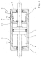
Die einzige Figur zeigt eine Betätigungseinrichtung für das in der EP 0 510 457 B1 gezeigte Verteiler- und Ausgleichsgetriebe, welche hiermit vollständig mitumfaßt sein soll.The single figure shows an actuator for the distribution and differential gear shown in EP 0 510 457 B1, which hereby be completely encompassed should.
Die Betätigungseinrichtung besteht aus einem doppelt
wirkenden hydraulischen Zylinder 1, in welchem ein Kolben 2
verschiebbar gelagert ist. Soll die Sperre in Schließrichtung
betätigt werden, wird Druck über eine Druckzuführung 3
in einen ersten Kolbenraum 4 geleitet, wodurch dieser Druck
auf die Kolbenfläche 5 wirkt. Der Kolbenraum 6 bleibt bis
zu einem definierten Kolbenweg entlüftet, da der Kolbenraum
6 über eine Leitung 7 mit einem Druckmittelreservoir 8
verbunden ist. Eine Druckzuführung 9, welche ebenfalls mit
einer nicht gezeigten Druckmittelquelle verbindbar ist,
wird, wenn der Kolben 2 sich in seiner Ausgangsstellung
befindet, von einem Steuerschieber 10 verschlossen. Durch
die Druckbeaufschlagung des Kolbenraums 4 bewegt sich der
Kolben 2 und der Steuerschieber 10 in Schließrichtung der
Sperre, wobei der Druck im Kolbenraum 4 beim Beginn der
Bewegung überwiegt, da der Kolbenraum 6 über die Leitung 7
mit dem Druckmittelreservoir 8 verbunden ist. Ab einem definierten
Verschiebeweg, bei welchem sich die Sperre im
Schließzustand befindet, verschließt der Steuerschieber 10
die Leitung 7 und öffnet die Druckzuführung 9, wodurch der
Raum 6 ebenfalls mit Druck beaufschlagt wird. Da die Sperre
sich im geschlossenen Zustand befindet, wird der Druck im
Kolbenraum 4 reduziert und bei anliegendem Drehmoment die
Sperre im geschlossenen Zustand gehalten. Fällt das Drehmoment
unterhalb eines definierten Niveaus ab, so überwiegt
die Kraft aus dem Druck des Kolbenraums 6, wodurch die
Sperre im Öffnungssinne betätigt wird. The actuator consists of a double
acting
In einer weiteren Ausgestaltungsform besteht die Möglichkeit,
den Steuerschieber 10 entfallen zu lassen und den
Kolbenweg über einen Positionssensor zu ermitteln und in
Abhängigkeit des Kolbenwegs die Druckzuführung 3, die
Druckzuführung 9 und die Leitung 7 über Ventile mit Druckmittelquellen
oder dem Druckmittelreservoir zu verbinden. In another embodiment, it is possible
to dispense with the
- 11
- Hydraulikzylinderhydraulic cylinders
- 22
- Kolbenpiston
- 33
- Druckzuführungpressure feed
- 44
- Kolbenraumpiston chamber
- 55
- Kolbenflächepiston area
- 66
- Kolbenraumpiston chamber
- 77
- Leitungmanagement
- 88th
- DruckmittelreservoirPressure fluid reservoir
- 99
- Druckzuführungpressure feed
- 1010
- Steuerschieberspool
Claims (6)
Applications Claiming Priority (2)
| Application Number | Priority Date | Filing Date | Title |
|---|---|---|---|
| DE10334450A DE10334450A1 (en) | 2003-07-29 | 2003-07-29 | Clutch for drive differential in commercial vehicle or agricultural tractor has detected rotation rates of opposing clutch halves used for operation of double-action clutch engagement element |
| DE10334450 | 2003-07-29 |
Publications (3)
| Publication Number | Publication Date |
|---|---|
| EP1522767A2 true EP1522767A2 (en) | 2005-04-13 |
| EP1522767A3 EP1522767A3 (en) | 2005-04-20 |
| EP1522767B1 EP1522767B1 (en) | 2007-07-18 |
Family
ID=34071960
Family Applications (1)
| Application Number | Title | Priority Date | Filing Date |
|---|---|---|---|
| EP04017590A Expired - Fee Related EP1522767B1 (en) | 2003-07-29 | 2004-07-24 | Positive clutch for differential for vehicles |
Country Status (3)
| Country | Link |
|---|---|
| EP (1) | EP1522767B1 (en) |
| AT (1) | ATE367546T1 (en) |
| DE (2) | DE10334450A1 (en) |
Families Citing this family (10)
| Publication number | Priority date | Publication date | Assignee | Title |
|---|---|---|---|---|
| DE102008040206B4 (en) | 2008-07-07 | 2023-01-19 | Zf Friedrichshafen Ag | Use of a form-fitting clutch arrangement for a transfer case and/or a differential gear to implement a fail-safe solution for a parking brake |
| DE102009026708A1 (en) | 2009-06-04 | 2010-12-09 | Zf Friedrichshafen Ag | Arrangement with at least one jaw clutch |
| DE102009026706A1 (en) | 2009-06-04 | 2010-12-09 | Zf Friedrichshafen Ag | Bearing arrangement for a shaft |
| DE102009026707B4 (en) | 2009-06-04 | 2022-01-27 | Zf Friedrichshafen Ag | Arrangement with at least one dog clutch |
| DE102009026710A1 (en) | 2009-06-04 | 2010-12-09 | Zf Friedrichshafen Ag | Arrangement with at least one jaw clutch |
| DE102010045898A1 (en) * | 2010-04-12 | 2011-10-13 | Magna Powertrain Ag & Co Kg | coupling arrangement |
| DE102015219631A1 (en) | 2015-03-24 | 2016-09-29 | Zf Friedrichshafen Ag | Piston sleeve component for an actuator which can be acted upon with pressure medium, actuator which can be subjected to pressure medium and transfer case |
| DE102015205271A1 (en) | 2015-03-24 | 2016-09-29 | Zf Friedrichshafen Ag | Piston-sleeve element for a fluid-actuated actuator, fluid-actuated actuator and transfer case |
| EP3073127B1 (en) | 2015-03-24 | 2020-06-24 | ZF Friedrichshafen AG | Piston-sleeves component for an actuator which can be subjected to a pressurised medium, actuator which can be subjected to a pressurised medium and distributor gear |
| DE102018130721A1 (en) | 2018-12-03 | 2020-06-04 | Schaeffler Technologies AG & Co. KG | Bevel gear differential |
Citations (4)
| Publication number | Priority date | Publication date | Assignee | Title |
|---|---|---|---|---|
| US4570509A (en) * | 1983-06-13 | 1986-02-18 | Deere & Company | Differential lock control system responsive to steering and/or braking action to unlock differential |
| US5335764A (en) * | 1991-04-22 | 1994-08-09 | Steyr-Daimler-Puch Ag | Positively engaging clutch |
| DE4409585A1 (en) * | 1994-01-13 | 1995-07-20 | Knorr Bremse Systeme | Traction control system with pneumatic brake control for vehicles equipped with an automatic limited slip differential, in particular commercial vehicles, and method for engaging the differential lock |
| US6079539A (en) * | 1999-02-16 | 2000-06-27 | Dana Corporation | In-line axle disconnect assembly |
Family Cites Families (5)
| Publication number | Priority date | Publication date | Assignee | Title |
|---|---|---|---|---|
| FR2459393A1 (en) * | 1979-06-18 | 1981-01-09 | Jacottet Sa Ets | IMPROVEMENT TO VIBRATION CYLINDERS |
| DE4233115C2 (en) * | 1992-10-02 | 1995-04-13 | Ulrich Keller | Hydraulically operated locking and coupling device |
| DE4240076A1 (en) * | 1992-11-28 | 1994-06-01 | Bosch Gmbh Robert | Hydraulic control device for double work cylinder, esp steering appts. - controls both chambers of steering appts with proportional valve supplied by pressure source, and includes digital control circuit |
| DE4327507C2 (en) * | 1993-08-16 | 1996-07-18 | Steyr Daimler Puch Ag | Device for controlling the clutches in the drive train of a motor vehicle |
| DE19924388C1 (en) * | 1999-05-27 | 2001-07-26 | Daimler Chrysler Ag | Differential lock control process involves braking two shafts on alternate sides |
-
2003
- 2003-07-29 DE DE10334450A patent/DE10334450A1/en not_active Withdrawn
-
2004
- 2004-07-24 EP EP04017590A patent/EP1522767B1/en not_active Expired - Fee Related
- 2004-07-24 AT AT04017590T patent/ATE367546T1/en active
- 2004-07-24 DE DE502004004344T patent/DE502004004344D1/en active Active
Patent Citations (4)
| Publication number | Priority date | Publication date | Assignee | Title |
|---|---|---|---|---|
| US4570509A (en) * | 1983-06-13 | 1986-02-18 | Deere & Company | Differential lock control system responsive to steering and/or braking action to unlock differential |
| US5335764A (en) * | 1991-04-22 | 1994-08-09 | Steyr-Daimler-Puch Ag | Positively engaging clutch |
| DE4409585A1 (en) * | 1994-01-13 | 1995-07-20 | Knorr Bremse Systeme | Traction control system with pneumatic brake control for vehicles equipped with an automatic limited slip differential, in particular commercial vehicles, and method for engaging the differential lock |
| US6079539A (en) * | 1999-02-16 | 2000-06-27 | Dana Corporation | In-line axle disconnect assembly |
Also Published As
| Publication number | Publication date |
|---|---|
| EP1522767A3 (en) | 2005-04-20 |
| EP1522767B1 (en) | 2007-07-18 |
| DE502004004344D1 (en) | 2007-08-30 |
| ATE367546T1 (en) | 2007-08-15 |
| DE10334450A1 (en) | 2005-02-17 |
Similar Documents
| Publication | Publication Date | Title |
|---|---|---|
| EP0272570B1 (en) | Drive system for driven pairs of wheels | |
| DE3621225C1 (en) | Control device for temporarily switching a vehicle drive from a single-axis drive via a permanently driven vehicle axis to a two-axis drive | |
| DE102008040206B4 (en) | Use of a form-fitting clutch arrangement for a transfer case and/or a differential gear to implement a fail-safe solution for a parking brake | |
| DE3533745C2 (en) | ||
| WO2006128637A1 (en) | Friction clutch having a hydraulic actuator, and drive unit having at least one such friction clutch | |
| DE102006061516B4 (en) | Hydraulic arrangement for controlling two actuators | |
| DE102005023675A1 (en) | Torque-transmitting differential assembly with torque decoupling | |
| DE102009005410A1 (en) | Aktuierungsanordnung | |
| DE10025745A1 (en) | Variable pressure relief system for slip differential has limited slip assembly comprising hydraulic actuator coupled between case and one drive axle for selectively resisting relative rotation between drive axles | |
| DE3636260C2 (en) | ||
| DE102006014141A1 (en) | Automatic friction clutch e.g. single-disk dry clutch, controlling method for motor vehicle, involves changing clutch torque to new reference value in pressure-controlled manner and adjusting pressure of actuator to another reference value | |
| EP1522767B1 (en) | Positive clutch for differential for vehicles | |
| DE3611093C2 (en) | ||
| EP0262628B1 (en) | Drive assembly for an additionally engageable set of wheels | |
| DE3600870C1 (en) | Switching device for two clutches for switching between standard single-axle drive and two-axle all-wheel drive in a motor vehicle with two drivable vehicle axles | |
| DE102011109340A1 (en) | Method of disengaging positively closure clutch e.g. claw clutch in motor vehicle drive train, involves estimating clutch torque on closure clutch so that closure clutch is disengaged, only if estimated torque is below limit value | |
| EP2455249B1 (en) | Drive assembly for temporary four-wheel drive vehicles | |
| DE102018202918A1 (en) | Method for operating a drive train of a motor vehicle | |
| EP0143975B1 (en) | Farm tractor with two drivable axles, both with a differential gearing | |
| EP0928374B1 (en) | Automatic clutch | |
| EP2601066A2 (en) | Motor vehicle drive train device | |
| DE60130049T2 (en) | Four-wheel drive switch- | |
| DE102008001889A1 (en) | Power divider for distribution of drive torque of e.g. internal combustion engine of automobile on two drive axles, has driven element rotatable relative to input shaft, and intermediate element and housing detachably connected by brake | |
| DE102008037562B4 (en) | Longitudinal or transverse compensation unit for the drive train of a motor vehicle | |
| DE3330549C2 (en) |
Legal Events
| Date | Code | Title | Description |
|---|---|---|---|
| PUAI | Public reference made under article 153(3) epc to a published international application that has entered the european phase |
Free format text: ORIGINAL CODE: 0009012 |
|
| PUAL | Search report despatched |
Free format text: ORIGINAL CODE: 0009013 |
|
| AK | Designated contracting states |
Kind code of ref document: A2 Designated state(s): AT BE BG CH CY CZ DE DK EE ES FI FR GB GR HU IE IT LI LU MC NL PL PT RO SE SI SK TR |
|
| AX | Request for extension of the european patent |
Extension state: AL HR LT LV MK |
|
| AK | Designated contracting states |
Kind code of ref document: A3 Designated state(s): AT BE BG CH CY CZ DE DK EE ES FI FR GB GR HU IE IT LI LU MC NL PL PT RO SE SI SK TR |
|
| AX | Request for extension of the european patent |
Extension state: AL HR LT LV MK |
|
| 17P | Request for examination filed |
Effective date: 20050319 |
|
| AKX | Designation fees paid |
Designated state(s): AT DE FR SE |
|
| 17Q | First examination report despatched |
Effective date: 20060519 |
|
| GRAP | Despatch of communication of intention to grant a patent |
Free format text: ORIGINAL CODE: EPIDOSNIGR1 |
|
| GRAS | Grant fee paid |
Free format text: ORIGINAL CODE: EPIDOSNIGR3 |
|
| GRAA | (expected) grant |
Free format text: ORIGINAL CODE: 0009210 |
|
| AK | Designated contracting states |
Kind code of ref document: B1 Designated state(s): AT DE FR SE |
|
| REF | Corresponds to: |
Ref document number: 502004004344 Country of ref document: DE Date of ref document: 20070830 Kind code of ref document: P |
|
| REG | Reference to a national code |
Ref country code: SE Ref legal event code: TRGR |
|
| ET | Fr: translation filed | ||
| PLBE | No opposition filed within time limit |
Free format text: ORIGINAL CODE: 0009261 |
|
| STAA | Information on the status of an ep patent application or granted ep patent |
Free format text: STATUS: NO OPPOSITION FILED WITHIN TIME LIMIT |
|
| 26N | No opposition filed |
Effective date: 20080421 |
|
| PGFP | Annual fee paid to national office [announced via postgrant information from national office to epo] |
Ref country code: AT Payment date: 20140626 Year of fee payment: 11 Ref country code: FR Payment date: 20140708 Year of fee payment: 11 Ref country code: SE Payment date: 20140711 Year of fee payment: 11 |
|
| REG | Reference to a national code |
Ref country code: SE Ref legal event code: EUG |
|
| REG | Reference to a national code |
Ref country code: AT Ref legal event code: MM01 Ref document number: 367546 Country of ref document: AT Kind code of ref document: T Effective date: 20150724 |
|
| REG | Reference to a national code |
Ref country code: FR Ref legal event code: ST Effective date: 20160331 |
|
| PG25 | Lapsed in a contracting state [announced via postgrant information from national office to epo] |
Ref country code: SE Free format text: LAPSE BECAUSE OF NON-PAYMENT OF DUE FEES Effective date: 20150725 Ref country code: AT Free format text: LAPSE BECAUSE OF NON-PAYMENT OF DUE FEES Effective date: 20150724 Ref country code: FR Free format text: LAPSE BECAUSE OF NON-PAYMENT OF DUE FEES Effective date: 20150731 |
|
| PGFP | Annual fee paid to national office [announced via postgrant information from national office to epo] |
Ref country code: DE Payment date: 20190710 Year of fee payment: 16 |
|
| REG | Reference to a national code |
Ref country code: DE Ref legal event code: R119 Ref document number: 502004004344 Country of ref document: DE |
|
| PG25 | Lapsed in a contracting state [announced via postgrant information from national office to epo] |
Ref country code: DE Free format text: LAPSE BECAUSE OF NON-PAYMENT OF DUE FEES Effective date: 20210202 |