EP1522753A1 - Hydraulic double clutch - Google Patents
Hydraulic double clutch Download PDFInfo
- Publication number
- EP1522753A1 EP1522753A1 EP03023013A EP03023013A EP1522753A1 EP 1522753 A1 EP1522753 A1 EP 1522753A1 EP 03023013 A EP03023013 A EP 03023013A EP 03023013 A EP03023013 A EP 03023013A EP 1522753 A1 EP1522753 A1 EP 1522753A1
- Authority
- EP
- European Patent Office
- Prior art keywords
- hydraulic double
- double clutch
- clutch according
- clutch
- disk carrier
- Prior art date
- Legal status (The legal status is an assumption and is not a legal conclusion. Google has not performed a legal analysis and makes no representation as to the accuracy of the status listed.)
- Granted
Links
- 230000008878 coupling Effects 0.000 claims abstract description 21
- 238000010168 coupling process Methods 0.000 claims abstract description 21
- 238000005859 coupling reaction Methods 0.000 claims abstract description 21
- 230000005540 biological transmission Effects 0.000 claims description 20
- 230000009977 dual effect Effects 0.000 claims description 5
- 241000446313 Lamella Species 0.000 abstract 3
- 230000000149 penetrating effect Effects 0.000 abstract 1
- 239000012530 fluid Substances 0.000 description 37
- 238000004519 manufacturing process Methods 0.000 description 5
- 238000005452 bending Methods 0.000 description 4
- 239000000110 cooling liquid Substances 0.000 description 4
- 238000006243 chemical reaction Methods 0.000 description 3
- 238000006073 displacement reaction Methods 0.000 description 3
- 230000002093 peripheral effect Effects 0.000 description 3
- 238000007639 printing Methods 0.000 description 3
- 230000009467 reduction Effects 0.000 description 3
- 239000007787 solid Substances 0.000 description 3
- 239000000969 carrier Substances 0.000 description 2
- 239000002826 coolant Substances 0.000 description 2
- 238000001816 cooling Methods 0.000 description 2
- 238000005553 drilling Methods 0.000 description 2
- 239000000463 material Substances 0.000 description 2
- 230000000712 assembly Effects 0.000 description 1
- 238000000429 assembly Methods 0.000 description 1
- 230000008901 benefit Effects 0.000 description 1
- 238000002485 combustion reaction Methods 0.000 description 1
- 238000010276 construction Methods 0.000 description 1
- 238000011161 development Methods 0.000 description 1
- 230000018109 developmental process Effects 0.000 description 1
- 238000005516 engineering process Methods 0.000 description 1
- 238000009434 installation Methods 0.000 description 1
- 238000005096 rolling process Methods 0.000 description 1
- 238000000926 separation method Methods 0.000 description 1
- 230000008719 thickening Effects 0.000 description 1
- 230000007704 transition Effects 0.000 description 1
Images


Classifications
-
- F—MECHANICAL ENGINEERING; LIGHTING; HEATING; WEAPONS; BLASTING
- F16—ENGINEERING ELEMENTS AND UNITS; GENERAL MEASURES FOR PRODUCING AND MAINTAINING EFFECTIVE FUNCTIONING OF MACHINES OR INSTALLATIONS; THERMAL INSULATION IN GENERAL
- F16D—COUPLINGS FOR TRANSMITTING ROTATION; CLUTCHES; BRAKES
- F16D13/00—Friction clutches
- F16D13/22—Friction clutches with axially-movable clutching members
- F16D13/38—Friction clutches with axially-movable clutching members with flat clutching surfaces, e.g. discs
- F16D13/52—Clutches with multiple lamellae ; Clutches in which three or more axially moveable members are fixed alternately to the shafts to be coupled and are pressed from one side towards an axially-located member
-
- F—MECHANICAL ENGINEERING; LIGHTING; HEATING; WEAPONS; BLASTING
- F16—ENGINEERING ELEMENTS AND UNITS; GENERAL MEASURES FOR PRODUCING AND MAINTAINING EFFECTIVE FUNCTIONING OF MACHINES OR INSTALLATIONS; THERMAL INSULATION IN GENERAL
- F16D—COUPLINGS FOR TRANSMITTING ROTATION; CLUTCHES; BRAKES
- F16D25/00—Fluid-actuated clutches
- F16D25/06—Fluid-actuated clutches in which the fluid actuates a piston incorporated in, i.e. rotating with the clutch
- F16D25/062—Fluid-actuated clutches in which the fluid actuates a piston incorporated in, i.e. rotating with the clutch the clutch having friction surfaces
- F16D25/063—Fluid-actuated clutches in which the fluid actuates a piston incorporated in, i.e. rotating with the clutch the clutch having friction surfaces with clutch members exclusively moving axially
- F16D25/0635—Fluid-actuated clutches in which the fluid actuates a piston incorporated in, i.e. rotating with the clutch the clutch having friction surfaces with clutch members exclusively moving axially with flat friction surfaces, e.g. discs
- F16D25/0638—Fluid-actuated clutches in which the fluid actuates a piston incorporated in, i.e. rotating with the clutch the clutch having friction surfaces with clutch members exclusively moving axially with flat friction surfaces, e.g. discs with more than two discs, e.g. multiple lamellae
-
- F—MECHANICAL ENGINEERING; LIGHTING; HEATING; WEAPONS; BLASTING
- F16—ENGINEERING ELEMENTS AND UNITS; GENERAL MEASURES FOR PRODUCING AND MAINTAINING EFFECTIVE FUNCTIONING OF MACHINES OR INSTALLATIONS; THERMAL INSULATION IN GENERAL
- F16D—COUPLINGS FOR TRANSMITTING ROTATION; CLUTCHES; BRAKES
- F16D21/00—Systems comprising a plurality of actuated clutches
- F16D21/02—Systems comprising a plurality of actuated clutches for interconnecting three or more shafts or other transmission members in different ways
- F16D21/06—Systems comprising a plurality of actuated clutches for interconnecting three or more shafts or other transmission members in different ways at least two driving shafts or two driven shafts being concentric
-
- F—MECHANICAL ENGINEERING; LIGHTING; HEATING; WEAPONS; BLASTING
- F16—ENGINEERING ELEMENTS AND UNITS; GENERAL MEASURES FOR PRODUCING AND MAINTAINING EFFECTIVE FUNCTIONING OF MACHINES OR INSTALLATIONS; THERMAL INSULATION IN GENERAL
- F16D—COUPLINGS FOR TRANSMITTING ROTATION; CLUTCHES; BRAKES
- F16D25/00—Fluid-actuated clutches
- F16D25/10—Clutch systems with a plurality of fluid-actuated clutches
-
- F—MECHANICAL ENGINEERING; LIGHTING; HEATING; WEAPONS; BLASTING
- F16—ENGINEERING ELEMENTS AND UNITS; GENERAL MEASURES FOR PRODUCING AND MAINTAINING EFFECTIVE FUNCTIONING OF MACHINES OR INSTALLATIONS; THERMAL INSULATION IN GENERAL
- F16D—COUPLINGS FOR TRANSMITTING ROTATION; CLUTCHES; BRAKES
- F16D21/00—Systems comprising a plurality of actuated clutches
- F16D21/02—Systems comprising a plurality of actuated clutches for interconnecting three or more shafts or other transmission members in different ways
- F16D21/06—Systems comprising a plurality of actuated clutches for interconnecting three or more shafts or other transmission members in different ways at least two driving shafts or two driven shafts being concentric
- F16D2021/0607—Double clutch with torque input plate in-between the two clutches, i.e. having a central input plate
-
- F—MECHANICAL ENGINEERING; LIGHTING; HEATING; WEAPONS; BLASTING
- F16—ENGINEERING ELEMENTS AND UNITS; GENERAL MEASURES FOR PRODUCING AND MAINTAINING EFFECTIVE FUNCTIONING OF MACHINES OR INSTALLATIONS; THERMAL INSULATION IN GENERAL
- F16D—COUPLINGS FOR TRANSMITTING ROTATION; CLUTCHES; BRAKES
- F16D21/00—Systems comprising a plurality of actuated clutches
- F16D21/02—Systems comprising a plurality of actuated clutches for interconnecting three or more shafts or other transmission members in different ways
- F16D21/06—Systems comprising a plurality of actuated clutches for interconnecting three or more shafts or other transmission members in different ways at least two driving shafts or two driven shafts being concentric
- F16D2021/0661—Hydraulically actuated multiple lamellae clutches
-
- F—MECHANICAL ENGINEERING; LIGHTING; HEATING; WEAPONS; BLASTING
- F16—ENGINEERING ELEMENTS AND UNITS; GENERAL MEASURES FOR PRODUCING AND MAINTAINING EFFECTIVE FUNCTIONING OF MACHINES OR INSTALLATIONS; THERMAL INSULATION IN GENERAL
- F16D—COUPLINGS FOR TRANSMITTING ROTATION; CLUTCHES; BRAKES
- F16D21/00—Systems comprising a plurality of actuated clutches
- F16D21/02—Systems comprising a plurality of actuated clutches for interconnecting three or more shafts or other transmission members in different ways
- F16D21/06—Systems comprising a plurality of actuated clutches for interconnecting three or more shafts or other transmission members in different ways at least two driving shafts or two driven shafts being concentric
- F16D2021/0692—Systems comprising a plurality of actuated clutches for interconnecting three or more shafts or other transmission members in different ways at least two driving shafts or two driven shafts being concentric with two clutches arranged axially without radial overlap
Definitions
- the invention relates to a hydraulic double clutch for a transmission with two coaxially arranged transmission input shafts.
- This includes a driven clutch housing and two hydraulically actuated clutches with friction plates and annular actuating piston.
- the first clutch connects the clutch housing to the first transmission input shaft switchable, the second clutch connects the clutch housing with the second transmission input shaft also switchable. Both couplings have a common inner disk carrier on.
- the object of the invention is therefore a double clutch in a compact design with high torque capacity to create which is relatively inexpensive to produce and has a low weight.
- a hydraulic double clutch of the generic type is inventively provided that the inner disk carrier penetrates one of the actuating piston exclusivelyddom and that this end side of the inner disk carrier rotatably with the clutch housing connected is.
- An initiated via the clutch housing Torque is thus directly on the inner disk carrier transferred without the clutch hub itself transmits torque.
- a torque-transmitting coupling web not necessary.
- the reduction of torque transmitting Parts leads on the one hand to a reduction of the Own weight and beyond other and usual Design variants for a reduction of the material and manufacturing costs.
- the outer dimensions of the double clutch are in Essentially determined by the friction plates. In addition comes the Space requirement for the annular actuating piston.
- a particularly compact design can be achieved if one the friction plates of the two clutches axially in succession arranges.
- the two clutches a common pressure plate on.
- the pressure plate rotatably with the inner disk carrier connect to.
- the pressure plate can (single or double sided) be axially impacted or in the axial direction be fixed.
- a tacking or fixation can help with a locking ring or the like.
- one Compact design can be achieved by these measures functional separation of the two couplings.
- the pressure plate can also be rigidly connected to the inner disk carrier.
- production engineering and therefore cost reasons will be decisive whether the person skilled in the art only thinks for an axial impact, an axial fixation or for a rigid connection, for example a one-piece design decides.
- hydraulic double clutch penetrates the inner disc carrier the other of the actuating piston on the other end.
- the inner disk carrier in particular also be executed axially mirror-symmetrical.
- the inner disk carrier radially end supports the other end and / or centered and / or rotationally locking and / or rotationally fixed holds.
- the inner disk carrier Forces and / or forces acting in the circumferential direction in this way not alone at the transition clutch housing inner disc carrier, but also about the other one Actuating piston added.
- a preferred embodiment provides that the coupling housing is rotatably connected to a clutch hub and that a cylinder is provided which on the clutch hub is axially impacted and on which the other actuating piston is guided axially displaceable. Based according to the above-described embodiment of the inner disk carrier other end side on the other actuating piston off, then any occurring forces or moments taken over the cylinder from the clutch hub.
- the invention provides that the cylinder, the inner disc carrier at the other end radially supports and / or centered and / or anti-rotation and / or rotatably holds. Alternatively or additionally, so the forces and / or moments described above immediately taken up by the clutch hub via this cylinder.
- the clutch housing or the clutch hub another cylinder have, on which the one actuating piston axially slidably guided.
- this is another cylinder essentially mirror-symmetrical in the axial direction the cylinder described above.
- the invention provides that the two actuating pistons against the force of one or more return spring (s) are operable.
- Return springs of any type can be used.
- the return springs plate springs, coil springs or corrugated springs.
- the return springs can be supported against a compensating piston be.
- a compensating piston serves to limit a hydraulic fluid compensation chamber in which an increasing hydraulic fluid pressure with increasing speed is built, which the hydraulic fluid pressure in a necessary for the actuation of the clutches Counteracts pressure chamber and unintentional actuation of the each clutch prevented.
- the return springs of the two Actuating piston also supported against a common support element be.
- the reaction forces of the return springs of the two Actuation piston then act against each other. Forces up Other components of the double clutch are therefore low.
- the common support element preferably a ring element, which axially on the clutch hub impacted and / or rotatably connected to the clutch hub is and / or axially fixed to the clutch hub and / or rigidly connected to the clutch hub.
- the expert decides in turn depends in particular of design, material and manufacturing costs from.
- the two actuating piston in each case a compensation piston is assigned, which in each case against the inner disk carrier support.
- the inner disk carrier is circumferential on the inner circumference Has (or interrupted) circumferential webs.
- a hit can also be realized with the help of retaining rings.
- the respective Each actuating piston associated with a compensation piston be, which are supported against a common support element.
- a support member may according to the above description a ring element may be provided which axially the clutch hub is engaged and / or rotationally fixed with the Coupling hub is connected and / or axially on the clutch hub is fixed and / or rigidly connected to the clutch hub is.
- the invention further provides that the friction plates friction surfaces have, the mean friction radii substantially are identical.
- This variant has the advantage that both clutches of the dual clutch are substantially identical Forces and / or moments can be transmitted. Both couplings thus have a very similar switching behavior.
- the two clutches in axial direction substantially mirror-symmetrical to each other train.
- FIG. 1 illustrates a section of a FIG exemplified powertrain for a motor vehicle a possible basic structure and the operation of an inventive designed double clutch.
- crankshaft 24 indicated which, for example, with an internal combustion engine, a motor or the like is coupled. This page represents the drive side of the powertrain.
- the first transmission input shaft central or full wave 10 to operate all odd gears (eg, 1, 3, 5 ”) and the second transmission input shaft (Hollow shaft 9) for the operation of all even gears (eg 2, 4, 6 ...) of the motor vehicle.
- the reverse gear could be both the first transmission input shaft (central or Full shaft 10), as well as the second transmission input shaft Be assigned (full shaft 9) of the transmission.
- the drive train further includes a flywheel 21, a flexible / wobble disc 18, a torsional vibration damper 12 and the above inventively designed Double coupling.
- This drive train is enclosed by an outer housing.
- This outer housing is characterized by the so-called Clutch bell 74 formed.
- This clutch bell 74 consequently encloses the two as wet-running multi-plate clutches running clutches, the torsional vibration damper 12, the bending and / or tumbling disc 18 and the flywheel 21st
- the torsion or vibration damper 12 is in itself trained manner. He points on the input side a primary element 14 in the form of a half-shell. On the output side is a secondary element consisting of a first Half shell 13 and a second half shell 11, which at the same time the clutch housing forms provided. Primary element 14 and Secondary element 13, 11 are over a plurality of on the outer periphery the torsional vibration damper 12 arranged spring assemblies coupled in the direction of rotation a torque transferable. exemplary is a spring package shown in the drawing.
- the two half shells 11 and 14 of the torsional vibration damper 12 enclose the two individual clutches of the double clutch.
- Each clutch comprises in each case an outer disk carrier 1, 2 and a common inner disk carrier 40.
- the outer disk carrier the first clutch is subsequently used as the first outer disk carrier 1, the outer disk carrier of the second clutch is referred to below as a second outer disk carrier 2.
- the two outer disk carrier 1, 2 are half-shell-shaped formed, wherein the first outer disk carrier 1, the second Outer plate carrier 2 in the axial direction outstanding surrounds.
- the inner disk carrier 40 has a substantially cylindrical Shape up and extend over the axially extending Areas of the half-shells 1, 2.
- the two outer disk carrier 1, 2 have internal teeth 5, 6, which for axially displaceable but essentially non-rotatable leadership of four in the present case corresponding external teeth 31, 32 having friction plates 29, 30 serve.
- the latter are usually also called outer disks 29, 30 denotes.
- each pressure plates 34, 37 are each pressure plates 34, 37 in the same way as the aforementioned inner plates 36 axially displaceable but essentially guided against rotation.
- outer friction plates / outer plates 29, 30, the inner Friction discs / inner discs 33, 36 and the two pressure plates 34, 37 and the common end plate 35 engage each other toothed in a conventional manner each one a clutch associated with disc pack 27, 28 forming one another.
- the two disk packs 27, 28 with the corresponding friction disks 29, 30, 33, 34, 35, 36, 37 are thus on the common Inner disk carrier 40 in the axial direction one behind the other arranged.
- the friction surfaces of all friction plates 29, 30, 33, 34, 35, 36, 37 are substantially the same size, so that the individual clutches have equivalent performance.
- the friction surfaces the friction plates have different diameters.
- each clutch is a hydraulically actuated actuating piston 43, 44 assigned.
- Each of these actuating piston 43, 44 can against one of Pressure plates 34, 37 force-transmitting and frictional engagement between the individual friction plates 29, 30, 33, 34, 35, 36, 37 generating and thus the respective clutch are pressed actuated.
- the common inner disk carrier 40 passes through the two necessary for actuating the clutches annular actuating piston 43, 44.
- the inner disk carrier each end over the outer circumference substantially axially extending webs, which corresponding openings 45, 46 of the respective actuating piston 43, 44 like a toothing succeed. On one side, these bars also reach through Correspondingly provided in the clutch housing 11 Openings 47.
- the openings 47 in the clutch housing 11 (and as a rule, the openings 45, 46 in the actuating piston 43, 44) are in their circumferential dimensions to each other agreed that a relative rotation is not possible.
- Coupling housing 11 are connected.
- a locking ring 48 is provided which the Inner disk carrier 40 holds fixed to the clutch housing 11.
- the coupling housing 11 is rigidly connected to an interface 67 a clutch hub 61 connected.
- This clutch hub 61 engages the two transmission input shafts 9, 10 coaxial.
- the Clutch hub 61 carries a half-shell-shaped cylinder 77th This cylinder 77 is by means of a locking ring 78 in limited to its axial displacement.
- Part of the clutch housing 11 is a cylinder 79 in to the cylinder 77 of the corresponding type. At the two cylinders 77, 79 are the respective actuating pistons 43, 44 axially slidably guided. Cylinder 77 and actuating piston 44th serve as a support and centering for the inner disk carrier 40th
- the actuators for the two clutches include in addition to the aforementioned actuating piston 43, 44, means derer the respective printing plates 34, 37 of the disk packs 27, 28 moved in the direction of the common end plates 35 can each be a pressure piston 49, 50, a piston 51, 52, a balance piston 55, 56 and a plurality in Circumferentially arranged coil springs 53, 54.
- the respective Actuation piston 43, 44 are supported against the outside the respective pressure piston 49, 50 from which axially displaceable on the cylinders 79, 77 and on the outer circumference of Clutch hub 61 are guided. Support inward the actuating piston 43, 44 against the piston 51, 52 from. These in turn are directed inwards against the Coil springs 53, 54 from.
- the coil springs 53, 54 are directed inwards against the outer surfaces of the compensation pistons 55, 56 supported. These compensation pistons 55, 56 are supported with their inner surfaces against radially inwards directed circumferential circumferential webs 57, 58 on the inner disk carrier 40 off.
- the entire clutch system immediately on the second Transmission input shaft (hollow shaft 9) could be stored, is a separate one in the present embodiment flange-like component, hereinafter referred to as carrier 62, provided, which the two transmission input shafts, the Hollow shaft 9 and the solid shaft 10, coaxially surrounds and on which the clutch hub 61 is rotatably mounted.
- carrier 62 flange-like component
- the clutch hub 61 on the carrier 62 are present Slide bearing used.
- Needle roller bearings can be used as an alternative for reduced friction moments Rolling (needle roller bearings) can be used.
- the carrier 62 may be integral or both axial and radial be executed in several parts.
- the carrier 62 in two parts. It consists of a coat and one of this enclosed socket.
- the cylinder jacket-shaped Bush has in its outer periphery in the axial direction extending, different lengths of longitudinal grooves.
- the coat has corresponding to the arrangement of the aforementioned longitudinal grooves four circumferentially extending grooves. These circumferential grooves are not shown here over radially extending Openings connected to the corresponding longitudinal grooves.
- the clutch hub 61 four substantially radially and partially axially inclined Openings, which subsequently as hydraulic fluid channels 63, 64, 65 and 66 are designated.
- Hydraulic fluid channels 63, 64, 65, 66 is a supply the piston formed by the pistons 43, 44, 49, 50, 55, 56 Volumes (first hydraulic fluid actuating chamber 71, second hydraulic fluid actuating chamber 72, first hydraulic fluid compensation chamber 69, second hydraulic fluid compensation chamber 70, cooling liquid space 73) with hydraulic fluid.
- the first hydraulic fluid actuating chamber 71 can be pressurized with hydraulic fluid via the first hydraulic fluid channel 63.
- This hydraulic fluid pressure pushes the pressure piston 49 and thus the actuating piston 45 and the piston 51 against the pressure of the coil springs 53 inwards.
- Such a displacement of the actuating piston 45 has the result that its outer circumference is pressed against the pressure plate 34 of the first clutch actuated.
- the fourth hydraulic fluid channel 66 of the second hydraulic fluid actuating chamber 72 with hydraulic fluid. Due to this hydraulic fluid pressure, the pressure piston 50 and thus the actuating piston 44 and the piston 52 against the pressure of the coil springs 54 is pressed inwards. This has the consequence in a corresponding manner that the outer circumference of the actuating piston 44 is pressed against the pressure plate 37 of the second clutch actuated.
- the hydraulic fluid in the hydraulic fluid compensation compartments 69, 70 serves a centrifugal force Hydraulic fluid back pressure to produce, which is the centrifugal pressure increase in the respective hydraulic fluid actuating chamber 71, 72 counteracts.
- the hydraulic fluid in the cooling liquid space 73 becomes the Cooling of the friction plates 29 30 33, 34, 35, 36, 37 by radially extending (not shown here) openings in the inner disk carrier 40 to the friction plates 29, 30, 33, 34, 35, 36, 37 guided.
- the drive train components described in detail above are connected as follows.
- the crankshaft 24 is bolted to the inner periphery of the flywheel 21 (Screw 26, bore 23).
- the outer circumference of the Flywheel 21 is with the outer periphery of the bending / tumbling soft Washer 18 riveted (outer edge bore 19, rivet 20, Bore 22).
- the inner circumference of the bending / tumbling disc 18 carries an inner flange 17 with an outer toothing.
- the secondary element 13 of the torsional vibration damper 12, which at the same time forms the clutch housing is in the above described manner rotatably with the inner disk carrier 40 of the double clutch connected.
- the two clutches (disk packs 27, 28; 44, 45) connect the inner disk carrier 40 switchable the outer disk carriers 1, 2, which in turn via the Flanges 3, 4 by means of splines 7, 8 against rotation with the two transmission input shafts 9, 10 are connected.
- crankshaft 24 torque can thus by means of the double clutch on one of the two transmission input shafts 9, 10 are transmitted.
- FIG. 2 shows a detail of a drive train of the type described above with a second embodiment a double clutch according to the invention.
- the illustrated in the figure 2 embodiment of an inventive Double clutch is different from the above described according to the figure 1 in that the compensation piston 55, 56 not against against the inner disk carrier arranged circumferential webs 57, 58 are supported, but against a ring member 59, which by a locking ring 60 is limited stop supported on the clutch hub 61.
- the ring member 59 has the task of hydraulic fluid flow to the friction plates 29, 30, 33, 34, 35, 36, 37 to guide.
- the ring element 59 has a thickening on the outer peripheral side, which incoming hydraulic fluid in the axial direction deflects.
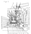
- FIG. 3 shows a detail of a further drive train of the type indicated above with a third Embodiment of a double clutch according to the invention.
- the embodiment illustrated in FIG. 3 differs from the double clutches according to the first two Embodiments in that on the compensation piston 55, 56 was completely dispensed with.
- Coil springs 53, 54 are now a plurality in Circumferentially arranged coil springs 53 a provided against which the actuating piston 43 exclusivelyd mineral on the Piston 51 and the actuating piston 44 on the other end over the piston 52 is supported.
- twodeckenkeitsleitbleche 75, 76 are provided, which are rigidly connected to the inner disk carrier and which the hydraulic fluid to the friction plates 29, 30, 33, 34, 35, 36, 37 lead to the cooling.
Landscapes
- Engineering & Computer Science (AREA)
- General Engineering & Computer Science (AREA)
- Mechanical Engineering (AREA)
- Hydraulic Clutches, Magnetic Clutches, Fluid Clutches, And Fluid Joints (AREA)
Abstract
Description
Die Erfindung bezieht sich auf eine hydraulische Doppelkupplung für ein Getriebe mit zwei koaxial angeordneten Getriebeeingangswellen. Diese umfasst ein angetriebenes Kupplungsgehäuse und zwei hydraulisch betätigte Kupplungen mit Reiblamellen und ringförmigen Betätigungskolben. Die erste Kupplung verbindet das Kupplungsgehäuse mit der ersten Getriebeeingangswelle schaltbar, die zweite Kupplung verbindet das Kupplungsgehäuse mit der zweiten Getriebeeingangswelle ebenfalls schaltbar. Beide Kupplungen weisen einen gemeinsamen Innenlamellenträger auf.The invention relates to a hydraulic double clutch for a transmission with two coaxially arranged transmission input shafts. This includes a driven clutch housing and two hydraulically actuated clutches with friction plates and annular actuating piston. The first clutch connects the clutch housing to the first transmission input shaft switchable, the second clutch connects the clutch housing with the second transmission input shaft also switchable. Both couplings have a common inner disk carrier on.
Aus der EP 1 195 537 B1 ist eine Doppelkupplung des gattungsbildenden
Oberbegriffs des Patentanspruchs 1 bekannt. Hier ist
das Kupplungsgehäuse über eine Steckverzahnung mit einer Kupplungsnabe
verbunden. Die Kupplungsnabe trägt einen ringförmigen
Kupplungssteg, welcher den Innenlamellenträger drehfest
mit der Kupplungsnabe verbindet. Dieser Kupplungssteg trennt
die beiden Kupplungen in axialer Richtung räumlich. Dadurch
wird eine kompakte Bauweise mit hoher Drehmomentkapazität geschaffen.From
Obwohl sich eine derartige Bauweise dem Grunde nach bewährt hat, besteht weiterhin das Bedürfnis, die Herstellungskosten und das Gewicht einer derartigen Doppelkupplung zu reduzieren.Although such a construction basically proven has, the need persists, the production costs and reduce the weight of such a dual clutch.
Die Aufgabe der Erfindung ist es deshalb, eine Doppelkupplung in kompakter Bauweise mit hoher Drehmomentkapazität zu schaffen, welche vergleichsweise kostengünstig herstellbar ist und ein geringes Gewicht aufweist. The object of the invention is therefore a double clutch in a compact design with high torque capacity to create which is relatively inexpensive to produce and has a low weight.
Diese Aufgabe wird bei einer hydraulischen Doppelkupplung der
gattungsgemäßen Art mit Hilfe der Merkmale des kennzeichnenden
Teils des Patentanspruchs 1 gelöst. Vorteilhafte Ausführungen
und Weiterbildungen der Erfindung sind in den Unteransprüchen
angegeben.This task is in a hydraulic double clutch of
generic type with the help of the features of the characterizing
Part of
Bei einer hydraulischen Doppelkupplung der gattungsgemäßen Art ist erfindungsgemäß vorgesehen, dass der Innenlamellenträger einen der Betätigungskolben einendseitig durchdringt und dass diese Endseite des Innenlamellenträgers drehfest mit dem Kupplungsgehäuse verbunden ist. Ein über das Kupplungsgehäuse eingeleitetes Drehmoment wird damit unmittelbar auf den Innenlamellenträger übertragen, ohne dass die Kupplungsnabe selbst drehmomentübertragend wirkt. Ein drehmomentübertragender Kupplungssteg ist nicht erforderlich. Die Reduzierung drehmomentübertragender Teile führt einerseits zu einer Reduktion des Eigengewichts und darüber hinaus gegenüber anderen und üblichen Konstruktionsvarianten zu einer Verminderung der Material- und Herstellungskosten. Gleichzeitig wird durch diese Anordnung eine kompakte Bauweise bei hoher Drehmomentkapazität erreicht. Die äußeren Abmessungen der Doppelkupplung werden im Wesentlichen von den Reiblamellen bestimmt. Hinzu kommt der Platzbedarf für die ringförmigen Betätigungskolben.In a hydraulic double clutch of the generic type is inventively provided that the inner disk carrier penetrates one of the actuating piston einendseitig and that this end side of the inner disk carrier rotatably with the clutch housing connected is. An initiated via the clutch housing Torque is thus directly on the inner disk carrier transferred without the clutch hub itself transmits torque. A torque-transmitting coupling web not necessary. The reduction of torque transmitting Parts leads on the one hand to a reduction of the Own weight and beyond other and usual Design variants for a reduction of the material and manufacturing costs. At the same time by this arrangement a compact design with high torque capacity reached. The outer dimensions of the double clutch are in Essentially determined by the friction plates. In addition comes the Space requirement for the annular actuating piston.
Eine besonders kompakte Bauweise lässt sich erreichen, wenn man die Reiblamellen der beiden Kupplungen axial hintereinander anordnet. Vorzugsweise weisen hierbei die beiden Kupplungen eine gemeinsame Druckplatte auf.A particularly compact design can be achieved if one the friction plates of the two clutches axially in succession arranges. Preferably, in this case, the two clutches a common pressure plate on.
In besonders vorteilhafter Ausgestaltung dieser Variante ist vorgesehen, die Druckplatte drehfest mit dem Innenlamellenträger zu verbinden. Die Druckplatte kann (einseitig oder beidseitig) axial beanschlagt sein oder auch in axialer Richtung fixiert sein. Eine Beanschlagung oder Fixierung kann mit Hilfe eines Sicherungsrings oder dergleichen erfolgen. Neben einer kompakten Bauweise erreicht man durch diese Maßnahmen eine funktionale Trennung der beiden Kupplungen.In a particularly advantageous embodiment of this variant provided, the pressure plate rotatably with the inner disk carrier connect to. The pressure plate can (single or double sided) be axially impacted or in the axial direction be fixed. A tacking or fixation can help with a locking ring or the like. In addition to one Compact design can be achieved by these measures functional separation of the two couplings.
Anstelle einer axialen Fixierung kann die Druckplatte auch starr mit dem Innenlamellenträger verbunden sein. Fertigungstechnische und damit Kostengründe werden ausschlaggebend sein, ob sich der Fachmann lediglich für eine axiale Beanschlagung, eine axiale Fixierung oder für eine starre Verbindung beispielsweise eine einstückige Ausführung entscheidet.Instead of an axial fixation, the pressure plate can also be rigidly connected to the inner disk carrier. production engineering and therefore cost reasons will be decisive whether the person skilled in the art only thinks for an axial impact, an axial fixation or for a rigid connection, for example a one-piece design decides.
In einer besonders vorteilhaften Ausgestaltung der erfindungsgemäßen hydraulischen Doppelkupplung durchdringt der Innenlamellenträger den anderen der Betätigungskolben andernendseitig. Auf diese Weise kann der Innenlamellenträger insbesondere auch axial spiegelsymmetrisch ausgeführt werden.In a particularly advantageous embodiment of the invention hydraulic double clutch penetrates the inner disc carrier the other of the actuating piston on the other end. In this way, the inner disk carrier in particular also be executed axially mirror-symmetrical.
In besonderer Ausgestaltung dieser Ausführungsvariante ist erfindungsgemäß vorgesehen, dass der andere Betätigungskolben den Innenlamellenträger andernendseitig radial abstützt und/oder zentriert und/oder verdrehsichernd und/oder drehfest hält. In radialer Richtung auf den Innenlamellenträger wirkende Kräfte und/oder in Umfangsrichtung wirkende Kräfte werden auf diese Weise nicht allein am Übergang Kupplungsgehäuse Innenlamellenträger, sondern auch über den anderen Betätigungskolben aufgenommen.In a particular embodiment of this embodiment is according to the invention provided that the other actuating piston the inner disk carrier radially end supports the other end and / or centered and / or rotationally locking and / or rotationally fixed holds. In the radial direction acting on the inner disk carrier Forces and / or forces acting in the circumferential direction in this way not alone at the transition clutch housing inner disc carrier, but also about the other one Actuating piston added.
Eine bevorzugte Ausführungsvariante sieht vor, dass das Kupplungsgehäuse mit einer Kupplungsnabe drehfest verbunden ist und dass ein Zylinder vorgesehen ist, welcher an der Kupplungsnabe axial beanschlagt ist und an welchem der andere Betätigungskolben axial verschieblich geführt ist. Stützt sich entsprechend der vorbeschriebenen Ausführungsvariante der Innenlamellenträger andernendseitig an dem anderen Betätigungskolben ab, so werden etwaig auftretende Kräfte oder Momente über den Zylinder von der Kupplungsnabe aufgenommen.A preferred embodiment provides that the coupling housing is rotatably connected to a clutch hub and that a cylinder is provided which on the clutch hub is axially impacted and on which the other actuating piston is guided axially displaceable. Based according to the above-described embodiment of the inner disk carrier other end side on the other actuating piston off, then any occurring forces or moments taken over the cylinder from the clutch hub.
Alternativ oder zusätzlich ist erfindungsgemäß vorgesehen, dass der Zylinder den Innenlamellenträger andernendseitig radial abstützt und/oder zentriert und/oder verdrehsichernd und/oder drehfest hält. Alternativ oder zusätzlich werden also die vorstehend beschriebenen Kräfte und/oder Momente unmittelbar über diesen Zylinder von der Kupplungsnabe aufgenommen.Alternatively or additionally, the invention provides that the cylinder, the inner disc carrier at the other end radially supports and / or centered and / or anti-rotation and / or rotatably holds. Alternatively or additionally, so the forces and / or moments described above immediately taken up by the clutch hub via this cylinder.
In weiterer Ausgestaltung der Erfindung ist vorgesehen, dass das Kupplungsgehäuse oder die Kupplungsnabe einen weiteren Zylinder aufweisen, an welchem der eine Betätigungskolben axial verschieblich geführt ist. Vorzugsweise ist dieser weitere Zylinder im Wesentlichen spiegelsymmetrisch in Achsrichtung zu dem vorstehend beschriebenen Zylinder ausgeführt.In a further embodiment of the invention, it is provided that the clutch housing or the clutch hub another cylinder have, on which the one actuating piston axially slidably guided. Preferably, this is another cylinder essentially mirror-symmetrical in the axial direction the cylinder described above.
Weiter ist erfindungsgemäß vorgesehen, dass die beiden Betätigungskolben gegen die Kraft einer oder mehrerer Rückholfeder(n) betätigbar sind.Next, the invention provides that the two actuating pistons against the force of one or more return spring (s) are operable.
Es können Rückholfedern eines jeden Typs verwendet werden. Insbesondere können die Rückholfedern Tellerfedern, Schraubenfedern oder Wellfedern sein.Return springs of any type can be used. In particular, the return springs plate springs, coil springs or corrugated springs.
Die Rückholfedern können gegen einen Kompensationskolben abgestützt sein. Ein derartiger Kompensationskolben dient dazu, einen Hydraulikflüssigkeitsausgleichsraum zu begrenzen, in dem ein mit zunehmender Drehzahl zunehmender Hydraulikflüssigkeitsdruck aufgebaut wird, welcher dem Hydraulikflüssigkeitsdruck in einem zur Betätigung der Kupplungen notwendigen Druckraum entgegenwirkt und ein unbeabsichtigtes Betätigen der jeweiligen Kupplung verhindert.The return springs can be supported against a compensating piston be. Such a compensating piston serves to limit a hydraulic fluid compensation chamber in which an increasing hydraulic fluid pressure with increasing speed is built, which the hydraulic fluid pressure in a necessary for the actuation of the clutches Counteracts pressure chamber and unintentional actuation of the each clutch prevented.
Alternativ oder zusätzlich können die Rückholfedern der beiden Betätigungskolben auch gegen ein gemeinsames Stützelement abgestützt sein. Die Reaktionskräfte der Rückholfedern der beiden Betätigungskolben wirken dann gegeneinander. Kräfte auf sonstige Bauteile der Doppelkupplung sind damit gering.Alternatively or additionally, the return springs of the two Actuating piston also supported against a common support element be. The reaction forces of the return springs of the two Actuation piston then act against each other. Forces up Other components of the double clutch are therefore low.
Zur Reduzierung des Bauraumes ist das gemeinsame Stützelement vorzugsweise ein Ringelement, welches axial an der Kupplungsnabe beanschlagt und/oder drehfest mit der Kupplungsnabe verbunden ist und/oder axial an der Kupplungsnabe fixiert ist und/oder starr mit der Kupplungsnabe verbunden ist. Für welche Variante sich hierbei der Fachmann wiederum entscheidet, hängt insbesondere von Konstruktions-, Material- und Fertigungskosten ab.To reduce the installation space is the common support element preferably a ring element, which axially on the clutch hub impacted and / or rotatably connected to the clutch hub is and / or axially fixed to the clutch hub and / or rigidly connected to the clutch hub. For which Variant in this case the expert decides in turn depends in particular of design, material and manufacturing costs from.
Es ist nicht zwingend erforderlich, dass zur Abstützung der Rückholfedern der beiden Betätigungskolben besondere Stützvorrichtungen vorgesehen werden müssen. Vielmehr hat sich herausgestellt, dass sich die beiden Betätigungskolben auch gemeinsam gegen dieselben Rückholfedern abstützen können. Auch hier sind die jeweiligen Reaktionskräfte nach innen gerichtet. Jeder Betätigungskolben stützt sich somit gegenüber dem anderen Betätigungskolben ab. Diese Ausführungsvariante kommt mit einer geringen Anzahl an Bauelementen aus.It is not mandatory to support the Return springs of the two actuating piston special support devices must be provided. Rather, it has turned out that the two actuating pistons also together can support against the same return springs. Here too the respective reaction forces are directed inwards. Everyone Actuation piston thus supports against the other Actuating piston. This variant comes with a low number of components.
In weiterer Ausgestaltung der Erfindung ist vorgesehen, dass den beiden Betätigungskolben jeweils ein Kompensationskolben zugeordnet ist, welche sich jeweils gegen den Innenlamellenträger abstützen. Als Abstützeinrichtung ist es ausreichend, wenn der Innenlamellenträger innenumfangsseitig umlaufende (oder unterbrochene) Umfangsstege aufweist. Eine Beanschlagung kann auch mit Hilfe von Sicherungsringen realisiert sein.In a further embodiment of the invention, it is provided that the two actuating piston in each case a compensation piston is assigned, which in each case against the inner disk carrier support. As a support device, it is sufficient if the inner disk carrier is circumferential on the inner circumference Has (or interrupted) circumferential webs. A hit can also be realized with the help of retaining rings.
In weiterer Ausgestaltung der Erfindung kann den jeweiligen Betätigungskolben jeweils ein Kompensationskolben zugeordnet sein, welche sich gegen ein gemeinsames Stützelement abstützen. Als Stützelement kann entsprechend der vorstehenden Beschreibung ein Ringelement vorgesehen sein, welches axial an der Kupplungsnabe beanschlagt ist und/oder drehfest mit der Kupplungsnabe verbunden ist und/oder axial an der Kupplungsnabe fixiert ist und/oder starr mit der Kupplungsnabe verbunden ist.In a further embodiment of the invention, the respective Each actuating piston associated with a compensation piston be, which are supported against a common support element. As a support member may according to the above description a ring element may be provided which axially the clutch hub is engaged and / or rotationally fixed with the Coupling hub is connected and / or axially on the clutch hub is fixed and / or rigidly connected to the clutch hub is.
Die Erfindung sieht weiterhin vor, dass die Reiblamellen Reibflächen aufweisen, deren mittlere Reibradien im Wesentlichen identisch sind. Diese Ausführungsvariante hat den Vorteil, dass beide Kupplungen der Doppelkupplung im Wesentlichen identische Kräfte und/oder Momente übertragen können. Beide Kupplungen weisen somit ein sehr ähnliches Schaltverhalten auf.The invention further provides that the friction plates friction surfaces have, the mean friction radii substantially are identical. This variant has the advantage that both clutches of the dual clutch are substantially identical Forces and / or moments can be transmitted. Both couplings thus have a very similar switching behavior.
Ein weitgehend identisches Schaltverhalten wird dann erreicht, wenn die Reibflächen der Reiblamellen identisch sind.A largely identical switching behavior is then achieved when the friction surfaces of the friction plates are identical.
Sowohl aus konstruktiver, fertigungstechnischer als auch aus funktionaler Sicht ist es vorteilhaft, die beiden Kupplungen der Doppelkupplung soweit als möglich identisch auszuführen. Erfindungsgemäß ist daher vorgesehen, die beiden Kupplungen in axialer Richtung im Wesentlichen spiegelsymmetrisch zueinander auszubilden.Both constructive, manufacturing technology as well as From a functional point of view, it is advantageous to use the two clutches as far as possible identical to the double clutch. According to the invention is therefore provided, the two clutches in axial direction substantially mirror-symmetrical to each other train.
Drei Ausführungsbeispiele der Erfindung sind in der Zeichnung dargestellt und werden im Folgenden näher beschrieben. Es zeigen:
Figur 1- einen Antriebsstrang mit einem ersten Ausführungsbeispiel einer erfindungsgemäßen Doppelkupplung im Axialhalbschnitt,
- Figur 2
- einen Antriebsstrang mit einem zweiten Ausführungsbeispiel einer erfindungsgemäßen Doppelkupplung im Axialhalbschnitt,
Figur 3- einen Antriebsstrang mit einem dritten Ausführungsbeispiel einer erfindungsgemäßen Doppelkupplung im Axialhalbschnitt.
- FIG. 1
- a drive train with a first embodiment of a dual clutch according to the invention in the axial half section,
- FIG. 2
- a drive train with a second embodiment of a dual clutch according to the invention in the axial half section,
- FIG. 3
- a drive train with a third embodiment of a double clutch according to the invention in Axialhalbschnitt.
Die Figur 1 verdeutlicht anhand eines Ausschnittes aus einem beispielhaft gewählten Antriebsstrang für ein Kraftfahrzeug einen möglichen Grundaufbau und die Funktionsweise einer erfindungsgemäß gestalteten Doppelkupplung.FIG. 1 illustrates a section of a FIG exemplified powertrain for a motor vehicle a possible basic structure and the operation of an inventive designed double clutch.
Auf der rechten Seite der Zeichnungsfigur ist eine Kurbelwelle
24 angedeutet, welche beispielsweise mit einer Verbrennungskraftmaschine,
einem Motor oder dergleichen gekoppelt ist.
Diese Seite stellt die Antriebsseite des Antriebsstrangs dar.On the right side of the drawing figure is a
Auf der linken Seite des Zeichnungsblattes sind zwei Getriebeeingangswellen,
nämlich eine Zentral- oder Vollwelle 10 und
eine Hohlwelle 9 zu sehen, welche aus der Kupplungsglocke 74
der Doppelkupplung herausgeführt sind und beispielsweise mit
einem hier nicht dargestellten Getriebe oder dergleichen gekoppelt
sind. Diese Seite stellt die Abtriebsseite des Antriebsstrangs
dar.On the left side of the drawing sheet are two transmission input shafts,
namely a central or
So kann beispielsweise die erste Getriebeeingangswelle (Zentral-
oder Vollwelle 10) zum Betrieb aller ungeraden Gänge
(z. B. 1, 3, 5 ...) und die zweite Getriebeeingangswelle
(Hohlwelle 9) zum Betrieb aller geraden Gänge (z. B. 2, 4, 6
...) des Kraftfahrzeugs vorgesehen sein. Der Rückwärtsgang
könnte sowohl der ersten Getriebeeingangswelle (Zentral- oder
Vollwelle 10), als auch der zweiten Getriebeeingangswelle
(Vollwelle 9) des Getriebes zugeordnet sein.For example, the first transmission input shaft (central
or full wave 10) to operate all odd gears
(eg, 1, 3, 5 ...) and the second transmission input shaft
(Hollow shaft 9) for the operation of all even gears (
Der Antriebsstrang umfasst ferner eine Schwungmasse 21, eine
biege-/taumelweiche Scheibe 18, einen Torsionsschwingungsdämpfer
12 sowie die vorstehend genannte erfindungsgemäß ausgestaltete
Doppelkupplung.The drive train further includes a
Dieser Antriebsstrang wird von einem äußeren Gehäuse umschlossen.
Dieses äußere Gehäuse wird durch die sogenannte vorerwähnte
Kupplungsglocke 74 gebildet. Diese Kupplungsglocke 74
umschließt folglich die beiden als nasslaufende Lamellenkupplungen
ausgeführten Kupplungen, den Drehschwingungsdämpfer 12,
die biege- und/oder taumelweiche Scheibe 18 sowie die Schwungmasse
21.This drive train is enclosed by an outer housing.
This outer housing is characterized by the so-called
Der Dreh- oder Torsionsschwingungsdämpfer 12 ist in an sich
bekannter Art und Weise ausgebildet. Eingangsseitig weist er
ein Primärelement 14 in Form einer Halbschale auf. Ausgangsseitig
ist ein Sekundärelement bestehend aus einer ersten
Halbschale 13 und einer zweiten Halbschale 11, welche zugleich
das Kupplungsgehäuse bildet, vorgesehen. Primärelement 14 und
Sekundärelement 13, 11 sind über eine Mehrzahl von an dem Außenumfang
des Drehschwingungsdämpfers 12 angeordnete Federpakete
in Drehrichtung ein Drehmoment übertragbar gekoppelt. Exemplarisch
ist ein Federpaket in der Zeichnung dargestellt. The torsion or
Die beiden Halbschalen 11 und 14 des Torsionsschwingungsdämpfers
12 umschließen die beiden einzelnen Kupplungen der Doppelkupplung.The two
Jede Kupplung umfasst jeweils einen Außenlamellenträger 1, 2
und einen gemeinsamen Innenlamellenträger 40. Der Außenlamellenträger
der ersten Kupplung wird nachfolgend als erster Außenlamellenträger
1, der Außenlamellenträger der zweiten Kupplung
wird im Folgenden als zweiter Außenlamellenträger 2 bezeichnet.Each clutch comprises in each case an
Die beiden Außenlamellenträger 1, 2 sind halbschalenförmig
ausgebildet, wobei der erste Außenlamellenträger 1 den zweiten
Außenlamellenträger 2 in axialer Richtung überragend umgreift.
Der Innenlamellenträger 40 weist eine im Wesentlichen zylinderförmige
Gestalt auf und erstreckt sich über die axial verlaufenden
Bereiche der Halbschalen 1, 2.The two
Die beiden Außenlamellenträger 1, 2 weisen Innenverzahnungen
5, 6 auf, welche zur axial verschieblichen aber im Wesentlichen
drehfesten Führung von im vorliegenden Fall jeweils vier
entsprechende Außenverzahnungen 31, 32 aufweisenden Reiblamellen
29, 30 dienen. Letztere werden üblicherweise auch als Außenlamellen
29, 30 bezeichnet.The two
In entsprechender Weise sind am Außenumfang der den jeweiligen
Außenlamellenträgern 1, 2 zugeordneten Innenlamellenträgerabschnitten
des gemeinsamen Innenlamellenträgers 40 Außenverzahnungen
41, 42 angeordnet, in denen Innenverzahnungen aufweisende
Reiblamellen, die sogenannten Innenlamellen 36, axial
verschieblich aber drehfest geführt sind. Die beiden Innenlamellenträgerabschnitte
werden durch eine gemeinsame Endplatte
35 voneinander getrennt. In a corresponding manner are on the outer circumference of the respective
An den beiden äußeren Enden des gemeinsamen Innenlamellenträgers
40 sind jeweils Druckplatten 34, 37 in gleicher Weise wie
die vorstehend genannten Innenlamellen 36 axial verschieblich
aber im Wesentlichen drehfest geführt.At the two outer ends of the common
Die äußeren Reiblamellen/Außenlamellen 29, 30, die inneren
Reiblamellen/Innenlamellen 33, 36 sowie die beiden Druckplatten
34, 37 und die gemeinsame Endplatte 35 greifen wechselseitig
verzahnungsartig in an sich bekannter Weise jeweils ein
einer Kupplung zugeordnetes Lamellenpaket 27, 28 bildend ineinander.The outer friction plates /
Die beiden Lamellenpakete 27, 28 mit den entsprechenden Reiblamellen
29, 30, 33, 34, 35, 36, 37 sind somit auf dem gemeinsamen
Innenlamellenträger 40 in axialer Richtung hintereinanderliegend
angeordnet. Im vorliegenden Ausführungsbeispiel
sind die Reibflächen aller Reiblamellen 29, 30, 33, 34, 35,
36, 37 im Wesentlichen gleich groß, sodass die einzelnen Kupplungen
eine gleichwertige Leistungsfähigkeit aufweisen.
Selbstverständlich ist es auch möglich, dass die Reibflächen
der Reiblamellen verschieden große Durchmesser aufweisen.The two disk packs 27, 28 with the
Bestandteile der Kupplungen sind ferner nachfolgend im Detail
beschriebene Kolben-/Zylindereinheiten, welche zur Betätigung
der Kupplungen dienen. Insbesondere ist jeder Kupplung ein
hydraulisch betätigbarer Betätigungskolben 43, 44 zugeordnet.
Jeder dieser Betätigungskolben 43, 44 kann gegen eine der
Druckplatten 34, 37 kraftübertragend und Reibschluss zwischen
den einzelnen Reiblamellen 29, 30, 33, 34, 35, 36, 37 erzeugend
und damit die jeweilige Kupplung betätigend gedrückt werden. Components of the clutches are also detailed below
described piston / cylinder units, which for actuation
serve the clutches. In particular, each clutch is a
hydraulically actuated actuating
Wie sich insbesondere der Figur 1 entnehmen lässt, werden die
beiden Kupplungen nach innen gerichtet betätigt, wobei die Reaktionskräfte
gegen die gemeinsame Endplatte 35 wirken.As can be seen in particular from Figure 1, the
both clutches are operated inwardly, with the reaction forces
act against the
Der gemeinsame Innenlamellenträger 40 durchsetzt die beiden
zur Betätigung der Kupplungen notwendigen ringförmigen Betätigungskolben
43, 44. Zu diesem Zweck weist der Innenlamellenträger
jeweils endseitig über dem Außenumfang im Wesentlichen
axial verlaufende Stege auf, welche entsprechende Öffnungen
45, 46 der jeweiligen Betätigungskolben 43, 44 verzahnungsartig
durchgreifen. Einendseitig durchgreifen diese Stege auch
korrespondierend hierzu im Kupplungsgehäuse 11 vorgesehene
Öffnungen 47. Die Öffnungen 47 im Kupplungsgehäuse 11 (sowie
in der Regel auch die Öffnungen 45, 46 in den Betätigungskolben
43, 44) sind in ihren Umfangsabmessungen so aufeinander
abgestimmt, dass eine Relativverdrehung nicht möglich ist. Der
Innenlamellenträger 40 ist auf diese Weise drehfest mit dem
Kupplungsgehäuse 11 verbunden.The common
Um eine axiale Verschiebung des Innenlamellenträgers 40 zu
verhindern, ist ein Sicherungsring 48 vorgesehen, welcher den
Innenlamellenträger 40 am Kupplungsgehäuse 11 fixiert hält.To an axial displacement of the
Das Kupplungsgehäuse 11 ist an einer Nahtstelle 67 starr mit
einer Kupplungsnabe 61 verbunden. Diese Kupplungsnabe 61 umgreift
die beiden Getriebeeingangswellen 9, 10 koaxial. Die
Kupplungsnabe 61 trägt einen halbschalenförmigen Zylinder 77.
Dieser Zylinder 77 ist mittels eines Sicherungsrings 78 in
seiner Axialverschiebung begrenzt.The
Bestandteil des Kupplungsgehäuses 11 ist ein Zylinder 79 in zu
dem Zylinder 77 korrespondierender Art. An den beiden Zylindern
77, 79 sind die jeweiligen Betätigungskolben 43, 44 axial
verschieblich geführt. Zylinder 77 und Betätigungskolben 44
dienen als Abstützung und Zentrierung für den Innenlamellenträger
40.Part of the
Die Betätigungseinrichtungen für die beiden Kupplungen umfassen
neben den vorerwähnten Betätigungskolben 43, 44, mittels
derer die jeweiligen Druckplatten 34, 37 der Lamellenpakete
27, 28 in Richtung der gemeinsamen Endplatten 35 verschoben
werden können, jeweils einen Druckkolben 49, 50, einen Kolben
51, 52, einen Ausgleichskolben 55, 56 sowie eine Mehrzahl in
Umfangsrichtung angeordneter Schraubenfedern 53, 54. Die jeweiligen
Betätigungskolben 43, 44 stützen sich nach außen gegen
die jeweiligen Druckkolben 49, 50 ab, welche axial verschieblich
an den Zylindern 79, 77 und am Außenumfang der
Kupplungsnabe 61 geführt sind. Nach innen gerichtet stützen
sich die Betätigungskolben 43, 44 gegen die Kolben 51, 52 ab.
Diese wiederum stützen sich nach innen gerichtet gegen die
Schraubenfedern 53, 54 ab. Die Schraubenfedern 53, 54 sind
nach innen gerichtet gegen die Außenflächen der Kompensationskolben
55, 56 abgestützt. Diese Kompensationskolben 55, 56
stützen sich mit deren Innenflächen gegen radial nach innen
gerichtete umlaufende Umfangsstege 57, 58 am Innenlamellenträger
40 ab.The actuators for the two clutches include
in addition to the
Obwohl das gesamte Kupplungssystem unmittelbar auf der zweiten
Getriebeeingangswelle (Hohlwelle 9) gelagert werden könnte,
ist bei der vorliegenden Ausführungsform ein separates
flanschartiges Bauteil, nachfolgend als Träger 62 bezeichnet,
vorgesehen, welches die beiden Getriebeeingangswellen, die
Hohlwelle 9 und die Vollwelle 10, koaxial umgreift und auf
welchem die Kupplungsnabe 61 drehbar gelagert ist. Zur Lagerung
der Kupplungsnabe 61 auf dem Träger 62 werden vorliegend
Gleitlager verwendet. Als Alternative für reduzierte Reibmomente
können Wälzlager (Nadellager) verwendet werden.Although the entire clutch system immediately on the second
Transmission input shaft (hollow shaft 9) could be stored,
is a separate one in the present embodiment
flange-like component, hereinafter referred to as
Der Träger 62 kann einteilig oder sowohl axial als auch radial
mehrteilig ausgeführt sein. Im vorliegenden Fall ist der Träger
62 zweiteilig ausgeführt. Er besteht aus einem Mantel und
einer von diesem umschlossenen Buchse. Die zylindermantelförmige
Buchse weist in deren Außenumfang in axialer Richtung
verlaufende, unterschiedlich lange Längsnuten auf. Der Mantel
weist korrespondierend zur Anordnung der vorerwähnten Längsnuten
vier in Umfangsrichtung verlaufende Nuten auf. Diese Umfangsnuten
sind über radial verlaufende hier nicht dargestellte
Öffnungen mit den entsprechenden Längsnuten verbunden.The
Korrespondierend zu den Umfangsnuten weist die Kupplungsnabe
61 vier im Wesentlichen radial und zum Teil axial geneigt verlaufende
Öffnungen auf, welche nachfolgend als Hydraulikflüssigkeitskanäle
63, 64, 65 und 66 bezeichnet sind. Über diese
Hydraulikflüssigkeitskanäle 63, 64, 65, 66 erfolgt eine Versorgung
der durch die Kolben 43, 44, 49, 50, 55, 56 gebildeten
Volumina (erster Hydraulikflüssigkeitsbetätigungsraum 71,
zweiter Hydraulikflüssigkeitsbetätigungsraum 72, erster Hydraulikflüssigkeitsausgleichsraum
69, zweiter Hydraulikflüssigkeitsausgleichsraum
70, Kühlflüssigkeitsraum 73) mit Hydraulikflüssigkeit.Corresponding to the circumferential grooves, the
Über den ersten Hydraulikflüssigkeitskanal 63 kann der erste
Hydraulikflüssigkeitsbetätigungsraum 71 mit Hydraulikflüssigkeit
druckbeaufschlagt werden. Dieser Hydraulikflüssigkeitsdruck
drückt den Druckkolben 49 und damit den Betätigungskolben
45 und den Kolben 51 entgegen dem Druck der Schraubenfedern
53 nach innen. Eine derartige Verschiebung des Betätigungskolbens
45 hat zur Folge, dass dessen Außenumfang gegen
die Druckplatte 34 der ersten Kupplung diese betätigend gedrückt
wird.
In gleicher Weise kann über den vierten Hydraulikflüssigkeitskanal
66 der zweite Hydraulikflüssigkeitsbetätigungsraum 72
mit Hydraulikflüssigkeit druckbeaufschlagt werden. Auf Grund
dieses Hydraulikflüssigkeitsdrucks wird der Druckkolben 50 und
damit der Betätigungskolben 44 und der Kolben 52 entgegen dem
Druck der Schraubenfedern 54 nach innen gedrückt. Dies hat in
entsprechender Weise zur Folge, dass der Außenumfang des Betätigungskolbens
44 gegen die Druckplatte 37 der zweiten Kupplung
diese betätigend gedrückt wird.The first hydraulic
In the same way can be pressurized via the fourth hydraulic
Über die beiden Hydraulikflüssigkeitskanäle 64 und 65 werden
einerseits die Hydraulikflüssigkeitsausgleichsräume 69, 70 als
auch der Kühlflüssigkeitsraum 73 mit Hydraulikflüssigkeit befüllt.Via the two hydraulic
Die Hydraulikflüssigkeit in den Hydraulikflüssigkeitsausgleichsräumen
69, 70 dient dazu, einen fliehkraftbedingten
Hydraulikflüssigkeitsgegendruck zu erzeugen, welcher der
fliehkraftbedingten Druckzunahme im jeweiligen Hydraulikflüssigkeitsbetätigungsraum
71, 72 entgegen wirkt.The hydraulic fluid in the hydraulic
Die Hydraulikflüssigkeit im Kühlflüssigkeitsraum 73 wird zur
Kühlung der Reiblamellen 29 30 33, 34, 35, 36, 37 durch radial
verlaufende (hier nicht dargestellte) Öffnungen im Innenlamellenträger
40 zu den Reiblamellen 29, 30, 33, 34, 35, 36, 37
geführt.The hydraulic fluid in the cooling
Die vorstehend im Detail beschriebenen Komponenten des Antriebsstranges
sind wie folgt miteinander verbunden. Die Kurbelwelle
24 ist mit dem Innenumfang der Schwungmasse 21 verschraubt
(Schraube 26, Bohrung 23). Der Außenumfang der
Schwungmasse 21 ist mit dem Außenumfang der biege-/taumelweichen
Scheibe 18 vernietet (Außenrandbohrung 19, Niete 20,
Bohrung 22). Der Innenumfang der biege-/taumelweichen Scheibe
18 trägt einen Innenflansch 17 mit einer Außenverzahnung. Diese
Außenverzahnung greift in der Art einer Steckverzahnung 16
in eine Innenverzahnung des Primärelements 14 des Torsionsschwingungsdämpfers
12 eine drehfeste Verbindung herstellend
ein.The drive train components described in detail above
are connected as follows. The
Das Sekundärelement 13 des Torsionsschwingungsdämpfers 12,
welches zugleich das Kupplungsgehäuse bildet, ist in vorstehend
beschriebener Weise drehfest mit dem Innenlamellenträger
40 der Doppelkupplung verbunden.The
Die beiden Kupplungen (Lamellenpakete 27, 28; Betätigungskolben
44, 45) verbinden den Innenlamellenträger 40 schaltbar mit
den Außenlamellenträgern 1, 2, welche wiederum über deren
Flansche 3, 4 mittels Steckverzahnung 7, 8 drehfest mit den
beiden Getriebeeingangswellen 9, 10 verbunden sind.The two clutches (disk packs 27, 28;
44, 45) connect the
Ein über die Kurbelwelle 24 eingeleitetes Drehmoment kann also
mittels der Doppelkupplung auf eine der beiden Getriebeeingangswellen
9, 10 übertragen werden.An introduced via the
Der Vollständigkeit halber sei erwähnt, dass eine über die
Kurbelwelle 24 eingeleitete Drehbewegung über ein an der Kupplungsnabe
61 angeordnetes Pumpenantriebszahnrad 68 auch eine
hier nicht dargestellte Hydropumpe zur Bereitstellung des vorstehend
erwähnten Hydraulikflüssigkeitsdrucks antreibt.For completeness, it should be mentioned that one on the
Die Figur 2 zeigt einen Ausschnitt aus einem Antriebsstrang der vorstehend beschriebenen Art mit einem zweiten Ausführungsbeispiel einer erfindungsgemäßen Doppelkupplung. FIG. 2 shows a detail of a drive train of the type described above with a second embodiment a double clutch according to the invention.
Das in der Figur 2 dargestellte Ausführungsbeispiel einer erfindungsgemäßen
Doppelkupplung unterscheidet sich von dem vorstehend
beschriebenen gemäß der Figur 1 dadurch, dass die Kompensationskolben
55, 56 nicht gegen an dem Innenlamellenträger
angeordnete umlaufende Stege 57, 58 abgestützt sind, sondern
gegen ein Ringelement 59, welches durch einen Sicherungsring
60 an der Kupplungsnabe 61 anschlagbegrenzt abgestützt ist.The illustrated in the figure 2 embodiment of an inventive
Double clutch is different from the above
described according to the figure 1 in that the
Neben der die Kompensationskolben 55, 56 und die Betätigungseinrichtungen
bestehend aus Betätigungskolben 43, 44, Druckkolben
43, 50, Kolben 51, 52 und Schraubenfedern 53, 54 in
axialer Richtung abstützenden Funktion hat das Ringelement 59
die Aufgabe den Hydraulikflüssigkeitsfluss zu den Reiblamellen
29, 30, 33, 34, 35, 36, 37 zu leiten. Zu diesem Zweck weist
das Ringelement 59 außenumfangsseitig eine Verdickung auf,
welche einströmende Hydraulikflüssigkeit in axiale Richtung
umlenkt.In addition to the
Die Figur 3 zeigt einen Ausschnitt aus einem weiteren Antriebsstrang der vorstehend angegebenen Art mit einem dritten Ausführungsbeispiel einer erfindungsgemäßen Doppelkupplung.FIG. 3 shows a detail of a further drive train of the type indicated above with a third Embodiment of a double clutch according to the invention.
Das in der Figur 3 dargestellte Ausführungsbeispiel unterscheidet
sich von den Doppelkupplungen gemäß den ersten beiden
Ausführungsbeispielen darin, dass auf die Kompensationskolben
55, 56 vollständig verzichtet wurde.The embodiment illustrated in FIG. 3 differs
from the double clutches according to the first two
Embodiments in that on the
Anstelle jeweils den einzelnen Betätigungskolben 43, 44 zugeordneten
Schraubenfedern 53, 54 sind nunmehr eine Mehrzahl in
Umfangsrichtung angeordneter Schraubenfedern 53a vorgesehen,
gegen welche der Betätigungskolben 43 einendseitig über den
Kolben 51 und der Betätigungskolben 44 andernendseitig über
den Kolben 52 abgestützt ist.Instead of each
Anstelle der beiden Kompensationskolben 55, 56 sind nunmehr
zwei Kühlflüssigkeitsleitbleche 75, 76 vorgesehen, welche
starr mit dem Innenlamellenträger verbunden sind und welche
die Hydraulikflüssigkeit zu den Reiblamellen 29, 30, 33, 34,
35, 36, 37 zu deren Kühlung leiten. Instead of the two
- 11
- erster Außenlamellenträgerfirst outer disk carrier
- 22
- zweiter Außenlamellenträgersecond outer disc carrier
- 33
- erster Flanschfirst flange
- 44
- zweiter Flanschsecond flange
- 55
- Innenverzahnunginternal gearing
- 66
- Innenverzahnunginternal gearing
- 77
- Steckverzahnungsplines
- 88th
- Steckverzahnungsplines
- 99
- Hohlwellehollow shaft
- 1010
- VollwelleSolid shaft
- 1111
- Kupplungsgehäuseclutch housing
- 1212
- Torsionsschwingungsdämpfertorsional vibration damper
- 1313
- Sekundärelementsecondary element
- 1414
- Primärelementprimary element
- 1515
- Primärflanschprimary flange
- 1616
- Steckverzahnungsplines
- 1717
- Innenflanschinner flange
- 1818
- biege-/taumelweiche Scheibebending / tumbling disc
- 1919
- AußenrandbohrungOuter edge hole
- 2020
- Nieterivet
- 2121
- SchwungmasseInertia
- 2222
- Bohrungdrilling
- 2323
- Bohrungdrilling
- 2424
- Kurbelwellecrankshaft
- 2525
- Gewindebohrungthreaded hole
- 2626
- Schraubescrew
- 2727
- erstes Lamellenpaketfirst plate pack
- 2828
- zweites Lamellenpaketsecond disc pack
- 2929
- Außenlamelleouter plate
- 3030
- Außenlamelleouter plate
- 3131
- Außenverzahnung external teeth
- 3232
- Außenverzahnungexternal teeth
- 3333
- Innenlamelleinner plate
- 3434
- Druckplatteprinting plate
- 3535
- Endplatteendplate
- 3636
- Innenlamelleinner plate
- 3737
- Druckplatteprinting plate
- 3838
- Innenverzahnunginternal gearing
- 3939
- Innenverzahnunginternal gearing
- 4040
- InnenlamellenträgerInner disk carrier
- 4141
- Außenverzahnungexternal teeth
- 4242
- Außenverzahnungexternal teeth
- 4343
- erster Betätigungskolbenfirst actuating piston
- 4444
- zweiter Betätigungskolbensecond actuating piston
- 4545
- Öffnungopening
- 4646
- Öffnungopening
- 4747
- Öffnungopening
- 4848
- Sicherungsringcirclip
- 4949
- Druckkolbenpressure piston
- 5050
- Druckkolbenpressure piston
- 5151
- Kolbenpiston
- 5252
- Kolbenpiston
- 5353
- Schraubenfedercoil spring
- 53a53a
- Schraubenfedercoil spring
- 5454
- Schraubenfedercoil spring
- 5555
- Kompensationskolbencompensation piston
- 5656
- Kompensationskolbencompensation piston
- 5757
- Umfangsstegperipheral land
- 5858
- Umfangsstegperipheral land
- 5959
- Ringelementring element
- 6060
- Sicherungsringcirclip
- 6161
- Kupplungsnabeclutch
- 6262
- Trägercarrier
- 6363
- Hydraulikflüssigkeitskanal Hydraulic fluid channel
- 6464
- HydraulikflüssigkeitskanalHydraulic fluid channel
- 6565
- HydraulikflüssigkeitskanalHydraulic fluid channel
- 6666
- HydraulikflüssigkeitskanalHydraulic fluid channel
- 6767
- Nahtstellejoin
- 6868
- PumpenantriebszahnradPump drive gear
- 6969
- erster Hydraulikflüssigkeitsausgleichsraumfirst hydraulic fluid compensation chamber
- 7070
- zweiter Hydraulikflüssigkeitsausgleichsraumsecond hydraulic fluid compensation chamber
- 7171
- erster Hydraulikflüssigkeitsbetätigungsraumfirst hydraulic fluid actuating chamber
- 7272
- zweiter Hydraulikflüssigkeitsbetätigungsraumsecond hydraulic fluid actuating chamber
- 7373
- KühlflüssigkeitsraumCooling liquid chamber
- 7474
- KupplungsglockeKupplungsglocke
- 7575
- erstes Kühlflüssigkeitsleitblechfirst coolant guide plate
- 7676
- zweites Kühlflüssigkeitsleitblechsecond coolant guide plate
- 7777
- Zylindercylinder
- 7878
- Zylindercylinder
- 7979
- Zylindercylinder
Claims (22)
dadurch gekennzeichnet, dass die beiden Kupplungen axial hintereinander angeordnet sind.Hydraulic double clutch according to claim 1,
characterized in that the two clutches are arranged axially one behind the other.
dadurch gekennzeichnet, dass die beiden Kupplungen eine gemeinsame Druckplatte (35) aufweisen. Hydraulic double clutch according to claim 2,
characterized in that the two clutches have a common pressure plate (35).
dadurch gekennzeichnet, dass die Druckplatte (35) drehfest mit dem Innenlamellenträger (40) verbunden ist.Hydraulic double clutch according to claim 3,
characterized in that the pressure plate (35) is non-rotatably connected to the inner disk carrier (40).
dadurch gekennzeichnet, dass die Druckplatte (35) axial beanschlagt oder axial fixiert ist.Hydraulic double clutch according to claim 4,
characterized in that the pressure plate (35) is axially impacted or axially fixed.
dadurch gekennzeichnet, dass die Druckplatte (35) starr mit dem Innenlamellenträger (40) verbunden ist.Hydraulic double clutch according to claim 5,
characterized in that the pressure plate (35) is rigidly connected to the inner disk carrier (40).
dadurch gekennzeichnet, dass der Innenlamellenträger (40) den anderen (44) der Betätigungskolben (43, 44) andernendseitig durchdringt.Hydraulic double clutch according to one of the preceding claims,
characterized in that the inner disk carrier (40) the other (44) of the actuating piston (43, 44) penetrates the other end.
dadurch gekennzeichnet, dass der andere Betätigungskolben (44) den Innenlamellenträger (40) andernendseitig radial abstützt und/oder zentriert und/oder verdrehsichernd und/oder drehfest hält.Hydraulic double clutch according to claim 7,
characterized in that the other actuating piston (44) supports the inner disk carrier (40) at the other end radially and / or centered and / or rotationally and / or rotatably holding.
dadurch gekennzeichnet, dass das Kupplungsgehäuse (11) mit einer Kupplungsnabe (61) drehfest verbunden ist und dass ein Zylinder (77) vorgesehen ist, welcher an der Kupplungsnabe (61) axial beanschlagt ist und an welcher der andere Betätigungskolben (44, 50) axial verschieblich geführt ist.Hydraulic double clutch according to one of the preceding claims,
characterized in that the clutch housing (11) is non-rotatably connected to a clutch hub (61) and that a cylinder (77) is provided, which is axially impacted on the clutch hub (61) and on which the other actuating piston (44, 50) axially slidably guided.
dadurch gekennzeichnet, dass der Zylinder (77) den Innenlamellenträger (40) andernendseitig radial abstützt und/oder zentriert und/oder verdrehsichernd und/oder drehfest hält.Hydraulic double clutch according to claim 9,
characterized in that the cylinder (77) supports the inner disk carrier (40) on the other end radially and / or centered and / or rotatably and / or rotationally holds.
dadurch gekennzeichnet, dass das Kupplungsgehäuse (11) oder die Kupplungsnabe einen weiteren Zylinder (79) aufweisen, an welchem der eine Betätigungskolben (45, 49) axial verschieblich geführt ist.Hydraulic double clutch according to one of the preceding claims,
characterized in that the clutch housing (11) or the clutch hub having a further cylinder (79) on which the one actuating piston (45, 49) is guided axially displaceably.
dadurch gekennzeichnet, dass die beiden Betätigungskolben (44, 45) gegen die Kraft einer oder mehrerer Rückholfeder(n) (53, 53a, 54) betätigbar sind.Hydraulic double clutch according to one of the preceding claims,
characterized in that the two actuating pistons (44, 45) against the force of one or more return spring (s) (53, 53 a, 54) are actuated.
dadurch gekennzeichnet, dass die Rückholfeder(n) eine Tellerfeder(n), eine Schraubenfeder(n) (53, 53a, 54) oder eine Wellfeder(n) ist/sind.Hydraulic double clutch according to claim 12,
characterized in that the return spring (s) is a plate spring (s), a coil spring (s) (53, 53a, 54) or a corrugated spring (s) is / are.
dadurch gekennzeichnet, dass die Rückholfeder(n) (53, 54) gegen einen Kompensationskolben (55, 56) abgestützt ist/sind. Hydraulic double clutch according to claim 12 or 13,
characterized in that the return spring (s) (53, 54) is supported against a compensating piston (55, 56).
dadurch gekennzeichnet, dass die Rückholfedern (53, 54) der beiden Betätigungskolben (44, 45) gegen ein gemeinsames Stützelement (59) oder gegen ein getrenntes Element abgestützt sind.Hydraulic double clutch according to one of claims 12 to 14,
characterized in that the return springs (53, 54) of the two actuating pistons (44, 45) are supported against a common support element (59) or against a separate element.
dadurch gekennzeichnet, dass das gemeinsame Stützelement ein Ringelement (59) ist, welches axial an der Kupplungsnabe (61) beanschlagt ist und/oder drehfest mit der Kupplungsnabe (61) verbunden ist und/oder axial an der Kupplungsnabe fixiert ist und/oder starr mit der Kupplungsnabe verbunden ist.Hydraulic double clutch according to claim 15,
characterized in that the common support member is a ring member (59) axially abutting the clutch hub (61) and / or rotatably connected to the clutch hub (61) and / or axially fixed to the clutch hub and / or rigidly with the clutch hub is connected.
dadurch gekennzeichnet, dass beide Betätigungskolben (45, 49, 51; 44, 50, 52) gemeinsam gegen dieselbe(n) Rückholfeder(n) (53a) abgestützt sind.Hydraulic double clutch according to one of claims 1 to 14,
characterized in that both actuating pistons (45, 49, 51; 44, 50, 52) are jointly supported against the same (n) return spring (s) (53a).
dadurch gekennzeichnet, dass den Betätigungskolben (45, 49, 51; 44, 50, 52) jeweils ein Kompensationskolben (55, 56) zugeordnet ist, welche sich gegen den Innenlamellenträger (40, 57, 58) abstützen.Hydraulic double clutch according to one of the preceding claims,
characterized in that the actuating piston (45, 49, 51, 44, 50, 52) in each case a compensation piston (55, 56) is associated, which are supported against the inner disk carrier (40, 57, 58).
dadurch gekennzeichnet, dass den Betätigungskolben (45, 49, 51; 44, 50, 52) jeweils ein Kompensationskolben (55, 56) zugeordnet ist, welche sich gegen ein gemeinsames Stützelement (59) abstützen, welches vorzugsweise ein Ringelement (59) ist, welches axial an der Kupplungsnabe (61) beanschlagt ist und/oder drehfest mit der Kupplungsnabe (61) verbunden ist und/oder axial an der Kupplungsnabe fixiert ist und/oder starr mit der Kupplungsnabe verbunden ist.Hydraulic double clutch according to one of claims 1 to 17,
characterized in that the actuating piston (45, 49, 51, 44, 50, 52) is assigned in each case a compensation piston (55, 56) which bears against a common support element (59), which is preferably a ring element (59), which is axially impacted on the clutch hub (61) and / or non-rotatably connected to the clutch hub (61) and / or is axially fixed to the clutch hub and / or rigidly connected to the clutch hub.
dadurch gekennzeichnet, dass alle Reiblamellen (29, 30, 33, 36, 34, 37, 35) Reibflächen aufweisen, deren mittlere Reibradien im Wesentlichen identisch sind.Hydraulic double clutch according to one of the preceding claims,
characterized in that all friction plates (29, 30, 33, 36, 34, 37, 35) have friction surfaces whose mean friction radii are substantially identical.
dadurch gekennzeichnet, dass die Reibflächen der Reiblamellen (29, 30, 33, 36, 34, 37, 35) identisch sind.Hydraulic double clutch according to claim 20,
characterized in that the friction surfaces of the friction plates (29, 30, 33, 36, 34, 37, 35) are identical.
dadurch gekennzeichnet, dass die beiden Kupplungen in axialer Richtung im Wesentlichen spiegelsymmetrisch zueinander ausgebildet sind.Hydraulic double clutch according to one of the preceding claims,
characterized in that the two couplings are formed in the axial direction substantially mirror-symmetrical to each other.
Priority Applications (9)
| Application Number | Priority Date | Filing Date | Title |
|---|---|---|---|
| EP03023013A EP1522753B1 (en) | 2003-10-11 | 2003-10-11 | Hydraulic double clutch |
| DE50302372T DE50302372D1 (en) | 2003-10-11 | 2003-10-11 | Hydraulic double clutch |
| EP04013095A EP1515059B1 (en) | 2003-09-09 | 2004-06-03 | Device for axially securing a clutch device on a rotary joint |
| DE200450006555 DE502004006555D1 (en) | 2003-09-09 | 2004-06-03 | Device for the axial securing of a coupling device on a rotary feedthrough |
| EP04020018A EP1522752A1 (en) | 2003-10-11 | 2004-08-24 | Drive train |
| JP2004251378A JP4607523B2 (en) | 2003-10-11 | 2004-08-31 | Hydraulic double clutch |
| US10/961,828 US7121392B2 (en) | 2003-10-11 | 2004-10-08 | Hydraulic double clutch |
| KR1020040080421A KR101080286B1 (en) | 2003-10-11 | 2004-10-08 | Hydraulic dual clutch |
| US10/962,370 US20050087420A1 (en) | 2003-10-11 | 2004-10-09 | Powertrain |
Applications Claiming Priority (1)
| Application Number | Priority Date | Filing Date | Title |
|---|---|---|---|
| EP03023013A EP1522753B1 (en) | 2003-10-11 | 2003-10-11 | Hydraulic double clutch |
Publications (2)
| Publication Number | Publication Date |
|---|---|
| EP1522753A1 true EP1522753A1 (en) | 2005-04-13 |
| EP1522753B1 EP1522753B1 (en) | 2006-02-08 |
Family
ID=34306893
Family Applications (1)
| Application Number | Title | Priority Date | Filing Date |
|---|---|---|---|
| EP03023013A Expired - Lifetime EP1522753B1 (en) | 2003-09-09 | 2003-10-11 | Hydraulic double clutch |
Country Status (5)
| Country | Link |
|---|---|
| US (1) | US7121392B2 (en) |
| EP (1) | EP1522753B1 (en) |
| JP (1) | JP4607523B2 (en) |
| KR (1) | KR101080286B1 (en) |
| DE (1) | DE50302372D1 (en) |
Cited By (9)
| Publication number | Priority date | Publication date | Assignee | Title |
|---|---|---|---|---|
| EP1686276A1 (en) | 2005-01-27 | 2006-08-02 | Getrag Ford Transmissions GmbH | Twin clutch with partition wall |
| EP1610016B2 (en) † | 2004-06-21 | 2011-11-16 | Schaeffler Technologies AG & Co. KG | Torque transmitting arrangement |
| CN103775532A (en) * | 2012-10-17 | 2014-05-07 | 舍弗勒技术股份两合公司 | Inline clutch with intermediate web |
| EP2759731A1 (en) | 2005-10-17 | 2014-07-30 | BorgWarner, Inc. | Coupling device for transferring a torque |
| EP2998603A1 (en) * | 2014-09-18 | 2016-03-23 | Valeo Embrayages | Dual wet clutch mechanism for a transmission system |
| EP1764523B2 (en) † | 2005-09-16 | 2017-10-25 | ZF Friedrichshafen AG | Multi-disc clutch device |
| DE102008055681B4 (en) * | 2008-10-28 | 2020-10-15 | Magna Pt B.V. & Co. Kg | Double clutch arrangement for a double clutch transmission |
| DE102007008946C5 (en) | 2006-02-27 | 2021-10-07 | Borgwarner Inc. | Multiple clutch for a vehicle with a hybrid drive |
| WO2023030565A1 (en) * | 2021-08-30 | 2023-03-09 | Schaeffler Technologies AG & Co. KG | Hydraulic assembly and electric axle drive train |
Families Citing this family (37)
| Publication number | Priority date | Publication date | Assignee | Title |
|---|---|---|---|---|
| JP2005164028A (en) * | 2003-10-06 | 2005-06-23 | Borgwarner Inc | Multi-clutch system with composite output system for power train transmission |
| EP1561961B1 (en) * | 2004-02-05 | 2007-09-12 | LuK Lamellen und Kupplungsbau Beteiligungs KG | Mulitple clutch device |
| US7246692B2 (en) * | 2004-10-26 | 2007-07-24 | Borgwarner Inc. | Dual clutch mechanism for a transmission |
| JP4773084B2 (en) * | 2004-12-22 | 2011-09-14 | 株式会社エクセディ | Double clutch device |
| EP1777426B1 (en) * | 2005-10-20 | 2008-10-08 | Getrag Ford Transmissions GmbH | Double clutch |
| DE102006031815B4 (en) * | 2006-07-07 | 2009-01-29 | Ortlinghaus-Werke Gmbh | Pressure oil clutch |
| US20080017469A1 (en) * | 2006-07-24 | 2008-01-24 | Mazda Motor Corporation | Automatic transmission |
| JP4770625B2 (en) * | 2006-07-24 | 2011-09-14 | マツダ株式会社 | Automatic transmission |
| DE102006042057B4 (en) * | 2006-09-05 | 2018-07-12 | Borgwarner Inc. | Coupling arrangement with angularly mounted blades for minimizing the total imbalance |
| DE102006042078B4 (en) * | 2006-09-05 | 2012-04-26 | Ortlinghaus-Werke Gmbh | Clutch with a first and a second piston-cylinder unit |
| EP2059689B1 (en) * | 2006-09-15 | 2015-06-24 | Borgwarner Inc. | Flexplate coupling for a wet clutch transmission |
| JP4765873B2 (en) * | 2006-09-28 | 2011-09-07 | マツダ株式会社 | Automatic transmission |
| US7600624B2 (en) * | 2006-10-11 | 2009-10-13 | Kabushiki Kaisha F.C.C. | Power transmission apparatus |
| JP4858093B2 (en) * | 2006-11-07 | 2012-01-18 | マツダ株式会社 | Automatic transmission |
| DE102007015104A1 (en) | 2007-03-29 | 2008-10-02 | Borg Warner Inc., Auburn Hills | Clutch device for transmitting torque between engine output shaft and clutch input shaft, has free-wheel arrangement with free-wheels that have inner and outer rings formed of one-piece with shafts |
| US10465754B2 (en) | 2007-03-30 | 2019-11-05 | Eaton Cummins Automated Transmission Technologies Llc | Dual clutch with cooling distribution reservoir chambers |
| US8479905B2 (en) | 2007-03-30 | 2013-07-09 | Eaton Corporation | Dual clutch arrangement with two piece main rotating manifold |
| US8967352B2 (en) * | 2007-03-30 | 2015-03-03 | Eaton Corporation | Low driven inertia dual clutch |
| DE102008045791B4 (en) * | 2007-11-11 | 2020-08-06 | Saic Motor Corp. Ltd. | Double clutch transmission and method for assembling a double clutch transmission |
| DE102008038101B4 (en) * | 2008-02-18 | 2019-09-19 | Borgwarner Inc. | Clutch damper unit |
| US9562572B2 (en) * | 2008-02-18 | 2017-02-07 | Borgwarner Inc. | Clutch device with a flex plate |
| EP2177286B1 (en) | 2008-10-15 | 2011-05-18 | Hoerbiger Antriebstechnik GmbH | Device for producing a coupling cage, in particular a double coupling, and bending device |
| DE102010010922C5 (en) * | 2009-08-14 | 2024-08-08 | Borgwarner Inc. | Parallel dual clutch device and drive train with such a parallel dual clutch device |
| US8757344B2 (en) | 2010-02-25 | 2014-06-24 | Borgwarner Inc. | Corrugated strip for splined clutch housing and hub |
| DE102010046633B4 (en) * | 2010-09-20 | 2012-10-18 | Gkn Stromag Ag | Double clutch |
| KR101305157B1 (en) * | 2011-07-29 | 2013-09-12 | 현대 파워텍 주식회사 | Dual clutch device |
| DE102012017955A1 (en) * | 2011-11-10 | 2013-05-16 | Borgwarner Inc. | Parallel DoppelkupuppIungseinrichtung and method for operating such a parallel dual clutch device |
| DE102012222915B4 (en) | 2012-12-12 | 2014-12-31 | Gkn Stromag Ag | Double clutch with two positively acting coupling units |
| FR3025271B1 (en) * | 2014-09-03 | 2016-11-04 | Valeo Embrayages | TRANSMISSION SYSTEM COMPRISING A WET DOUBLE CLUTCH MECHANISM |
| FR3026153B1 (en) * | 2014-09-18 | 2018-02-23 | Valeo Embrayages | TORQUE TRANSMISSION MODULE FOR EQUIPPING A TRANSMISSION OF A MOTOR VEHICLE |
| US10458484B2 (en) | 2015-09-22 | 2019-10-29 | C-Stone Technologies Co., Ltd. | Dual clutch |
| FR3041726B1 (en) * | 2015-09-24 | 2017-10-20 | Valeo Embrayages | TORQUE TRANSMISSION ASSEMBLY FOR EQUIPPING A TRANSMISSION OF A MOTOR VEHICLE |
| DE102017127219A1 (en) * | 2017-07-18 | 2019-01-24 | Schaeffler Technologies AG & Co. KG | Hybrid module with self-contained force flow of actuating forces |
| FR3090768B1 (en) * | 2018-12-20 | 2022-01-21 | Valeo Embrayages | Motor vehicle transmission device |
| KR102618258B1 (en) * | 2018-12-28 | 2023-12-27 | 주식회사 카펙발레오 | Dual clutch device for vehicle |
| DE102019001957C5 (en) * | 2019-03-20 | 2024-03-28 | Mercedes-Benz Group AG | Hybrid drive system |
| JP7476772B2 (en) * | 2020-11-19 | 2024-05-01 | マツダ株式会社 | Automatic transmission |
Citations (3)
| Publication number | Priority date | Publication date | Assignee | Title |
|---|---|---|---|---|
| DE9114528U1 (en) * | 1991-11-22 | 1992-02-13 | Zahnradfabrik Friedrichshafen Ag, 7990 Friedrichshafen | Double coupling |
| DE4239233A1 (en) * | 1992-11-21 | 1994-05-26 | Daimler Benz Ag | Hydraulic-fluid-actuated friction clutch with axially movable members - has single cylinder with piston between two pressure chambers, one having moving wall under pressure of spring |
| EP1195537A1 (en) * | 2000-10-05 | 2002-04-10 | Ford Global Technologies, Inc., A subsidiary of Ford Motor Company | Transmission double clutch with two input shafts |
Family Cites Families (23)
| Publication number | Priority date | Publication date | Assignee | Title |
|---|---|---|---|---|
| US116396A (en) * | 1871-06-27 | Improvement in stove-grates | ||
| US35328A (en) * | 1862-05-20 | Improved knife-cleaning box | ||
| US3589483A (en) * | 1970-01-27 | 1971-06-29 | Dana Corp | Variable speed transmission |
| US4463621A (en) * | 1981-12-23 | 1984-08-07 | Ford Motor Company | Multiple countershaft automatic transmission |
| JPH0781594B2 (en) * | 1985-08-31 | 1995-08-30 | 三菱自動車工業株式会社 | Power transmission device |
| US4741422A (en) * | 1987-03-09 | 1988-05-03 | General Motors Corporation | Clutch assembly with a pressure balance chamber |
| EP0321873B1 (en) | 1987-12-19 | 1994-08-03 | GETRAG Getriebe- und Zahnradfabrik Hermann Hagenmeyer GmbH & Cie | Dual clutch transmission and its adjustment method |
| US4947974A (en) * | 1988-01-15 | 1990-08-14 | Deere & Company | Fast fill hydraulic clutch |
| DE3819702A1 (en) * | 1988-06-09 | 1989-12-14 | Porsche Ag | HYDRAULICALLY OPERATED DOUBLE CLUTCH FOR A MOTOR VEHICLE |
| JPH04219557A (en) * | 1990-12-18 | 1992-08-10 | Mazda Motor Corp | Continuously variable transmission |
| DE4415664A1 (en) * | 1994-05-04 | 1995-11-09 | Zahnradfabrik Friedrichshafen | Coupling arrangement |
| DE19921687C5 (en) * | 1999-05-12 | 2016-06-09 | Borgwarner Inc. | Multiple clutch system for a transmission |
| DE10004179C5 (en) * | 1999-09-30 | 2017-06-29 | Volkswagen Ag | Multiple clutch device |
| DE10004195B4 (en) * | 1999-09-30 | 2013-02-07 | Volkswagen Ag | Multiple clutch device |
| DE10004190B4 (en) * | 1999-09-30 | 2013-02-07 | Volkswagen Ag | Multiple clutch device |
| JP2001263369A (en) | 2000-03-21 | 2001-09-26 | Aisin Seiki Co Ltd | Clutch device for automatic transmission |
| DE10115453B4 (en) | 2001-03-29 | 2014-08-07 | Zf Friedrichshafen Ag | Multiple coupling device, possibly in combination with a torsional vibration damper assembly and / or an electric machine |
| DE10115454A1 (en) | 2001-01-25 | 2002-08-08 | Zf Sachs Ag | Multiple clutch assembly, for a vehicle drive transmission train, is fitted as a unit with a clutch housing mounted in a bell at the gearbox housing, centered at the gearbox shafts and keyed against rotation |
| US6382382B1 (en) * | 2000-10-25 | 2002-05-07 | Ford Global Technologies, Inc. | Centrifugally balanced, pressure-operated clutch assembly |
| DE10203618A1 (en) | 2001-07-31 | 2003-02-13 | Zf Sachs Ag | Multiple clutch device for motor vehicles has modular unit of leadthrough with stator section and coupling device, for mounting on transmssion housing |
| DE10163404B4 (en) | 2001-12-21 | 2009-06-04 | Zf Sachs Ag | Method for controlling a clutch system with at least one multi-disc clutch arrangement |
| DE10230501A1 (en) | 2002-07-06 | 2004-01-15 | Zf Sachs Ag | Hydraulically actuated clutch system |
| DE10323514A1 (en) * | 2003-05-24 | 2004-12-23 | Dr.Ing.H.C. F. Porsche Ag | Coupling device, in particular multi-plate clutch for a double clutch transmission |
-
2003
- 2003-10-11 EP EP03023013A patent/EP1522753B1/en not_active Expired - Lifetime
- 2003-10-11 DE DE50302372T patent/DE50302372D1/en not_active Expired - Lifetime
-
2004
- 2004-08-31 JP JP2004251378A patent/JP4607523B2/en not_active Expired - Fee Related
- 2004-10-08 US US10/961,828 patent/US7121392B2/en not_active Expired - Fee Related
- 2004-10-08 KR KR1020040080421A patent/KR101080286B1/en not_active IP Right Cessation
Patent Citations (3)
| Publication number | Priority date | Publication date | Assignee | Title |
|---|---|---|---|---|
| DE9114528U1 (en) * | 1991-11-22 | 1992-02-13 | Zahnradfabrik Friedrichshafen Ag, 7990 Friedrichshafen | Double coupling |
| DE4239233A1 (en) * | 1992-11-21 | 1994-05-26 | Daimler Benz Ag | Hydraulic-fluid-actuated friction clutch with axially movable members - has single cylinder with piston between two pressure chambers, one having moving wall under pressure of spring |
| EP1195537A1 (en) * | 2000-10-05 | 2002-04-10 | Ford Global Technologies, Inc., A subsidiary of Ford Motor Company | Transmission double clutch with two input shafts |
Cited By (11)
| Publication number | Priority date | Publication date | Assignee | Title |
|---|---|---|---|---|
| EP1610016B2 (en) † | 2004-06-21 | 2011-11-16 | Schaeffler Technologies AG & Co. KG | Torque transmitting arrangement |
| EP1686276A1 (en) | 2005-01-27 | 2006-08-02 | Getrag Ford Transmissions GmbH | Twin clutch with partition wall |
| EP1764523B2 (en) † | 2005-09-16 | 2017-10-25 | ZF Friedrichshafen AG | Multi-disc clutch device |
| EP2759731A1 (en) | 2005-10-17 | 2014-07-30 | BorgWarner, Inc. | Coupling device for transferring a torque |
| DE102007008946C5 (en) | 2006-02-27 | 2021-10-07 | Borgwarner Inc. | Multiple clutch for a vehicle with a hybrid drive |
| DE102008055681B4 (en) * | 2008-10-28 | 2020-10-15 | Magna Pt B.V. & Co. Kg | Double clutch arrangement for a double clutch transmission |
| CN103775532A (en) * | 2012-10-17 | 2014-05-07 | 舍弗勒技术股份两合公司 | Inline clutch with intermediate web |
| CN103775532B (en) * | 2012-10-17 | 2017-12-15 | 舍弗勒技术股份两合公司 | Inline clutch with intermediate web |
| EP2998603A1 (en) * | 2014-09-18 | 2016-03-23 | Valeo Embrayages | Dual wet clutch mechanism for a transmission system |
| FR3026152A1 (en) * | 2014-09-18 | 2016-03-25 | Valeo Embrayages | DUAL WET CLUTCH MECHANISM FOR A TRANSMISSION SYSTEM |
| WO2023030565A1 (en) * | 2021-08-30 | 2023-03-09 | Schaeffler Technologies AG & Co. KG | Hydraulic assembly and electric axle drive train |
Also Published As
| Publication number | Publication date |
|---|---|
| US7121392B2 (en) | 2006-10-17 |
| DE50302372D1 (en) | 2006-04-20 |
| EP1522753B1 (en) | 2006-02-08 |
| JP2005121214A (en) | 2005-05-12 |
| KR101080286B1 (en) | 2011-11-08 |
| KR20050035100A (en) | 2005-04-15 |
| US20050082136A1 (en) | 2005-04-21 |
| JP4607523B2 (en) | 2011-01-05 |
Similar Documents
| Publication | Publication Date | Title |
|---|---|---|
| EP1522753B1 (en) | Hydraulic double clutch | |
| EP1941171B2 (en) | Coupling device for transmitting a torque | |
| EP1515059B1 (en) | Device for axially securing a clutch device on a rotary joint | |
| EP1568906B1 (en) | Double clutch | |
| EP1726842B1 (en) | Clutch assembly with radially adjoining clutches | |
| DE10223780C1 (en) | Gear shift mechanism, for an IC motor with a multiple hydraulic clutch, has a bearing flange around the gear housing opening as a support for the roller bearing between it and the clutch cage with the drive hub | |
| EP2153080B1 (en) | Dual clutch arrangement having a piston guide element | |
| EP3139053B1 (en) | Double coupling with standing pistons and improved engagement bearings | |
| EP1780435B1 (en) | Radially constructed dual clutch | |
| DE102010054545A1 (en) | Torque transfer device | |
| EP1371875B1 (en) | Device to damp rotational vibrations | |
| DE102006048653A1 (en) | Coupling device for transmitting torque between drive unit and clutch, has shafts that are coupled with each other in form fit manner, and spring pin and spring cylinder that generate pretension in form fit connection between shafts | |
| DE102004012948A1 (en) | Hydraulic double clutch for motor vehicle transmission has switching drive with clutch housing concentric to drive shafts | |
| DE4224361A1 (en) | PLANETARY WHEEL TRANSMISSION SYSTEM FOR AN AUTOMATIC TRANSMISSION | |
| DE102012209952A1 (en) | Double coupling | |
| EP1882865B1 (en) | Clutch arrangement for the drivetrain of a vehicle | |
| EP1522752A1 (en) | Drive train | |
| DE102006042057A1 (en) | Coupling arrangement for transmission of torque between rotating construction unit and another construction unit, has lamellae where total unbalance lamellae is minimzed during rotation of one or more lamellas by eccentric system | |
| EP1729025B1 (en) | Mulitple clutch device | |
| DE19820503B4 (en) | Torsional vibration damper with at least one bearing between damper elements | |
| EP1686275B1 (en) | Dual clutch | |
| WO2021244698A1 (en) | Friction clutch for transmitting a torque in a friction- and form-fitting manner | |
| EP2041444B1 (en) | Hydraulically-actuated clutch | |
| WO2009146967A1 (en) | Torque transmission system for the drive train of a vehicle | |
| EP1726843B1 (en) | Clutch assembly |
Legal Events
| Date | Code | Title | Description |
|---|---|---|---|
| PUAI | Public reference made under article 153(3) epc to a published international application that has entered the european phase |
Free format text: ORIGINAL CODE: 0009012 |
|
| 17P | Request for examination filed |
Effective date: 20040303 |
|
| AK | Designated contracting states |
Kind code of ref document: A1 Designated state(s): AT BE BG CH CY CZ DE DK EE ES FI FR GB GR HU IE IT LI LU MC NL PT RO SE SI SK TR |
|
| AX | Request for extension of the european patent |
Extension state: AL LT LV MK |
|
| GRAP | Despatch of communication of intention to grant a patent |
Free format text: ORIGINAL CODE: EPIDOSNIGR1 |
|
| GRAS | Grant fee paid |
Free format text: ORIGINAL CODE: EPIDOSNIGR3 |
|
| RAP1 | Party data changed (applicant data changed or rights of an application transferred) |
Owner name: BORGWARNER INC. |
|
| GRAA | (expected) grant |
Free format text: ORIGINAL CODE: 0009210 |
|
| AKX | Designation fees paid |
Designated state(s): DE FR GB IT |
|
| AK | Designated contracting states |
Kind code of ref document: B1 Designated state(s): DE FR GB IT |
|
| PG25 | Lapsed in a contracting state [announced via postgrant information from national office to epo] |
Ref country code: IT Free format text: LAPSE BECAUSE OF FAILURE TO SUBMIT A TRANSLATION OF THE DESCRIPTION OR TO PAY THE FEE WITHIN THE PRESCRIBED TIME-LIMIT;WARNING: LAPSES OF ITALIAN PATENTS WITH EFFECTIVE DATE BEFORE 2007 MAY HAVE OCCURRED AT ANY TIME BEFORE 2007. THE CORRECT EFFECTIVE DATE MAY BE DIFFERENT FROM THE ONE RECORDED. Effective date: 20060208 |
|
| REG | Reference to a national code |
Ref country code: GB Ref legal event code: FG4D Free format text: NOT ENGLISH |
|
| GBT | Gb: translation of ep patent filed (gb section 77(6)(a)/1977) |
Effective date: 20060208 |
|
| REF | Corresponds to: |
Ref document number: 50302372 Country of ref document: DE Date of ref document: 20060420 Kind code of ref document: P |
|
| ET | Fr: translation filed | ||
| PLBE | No opposition filed within time limit |
Free format text: ORIGINAL CODE: 0009261 |
|
| STAA | Information on the status of an ep patent application or granted ep patent |
Free format text: STATUS: NO OPPOSITION FILED WITHIN TIME LIMIT |
|
| 26N | No opposition filed |
Effective date: 20061109 |
|
| PGFP | Annual fee paid to national office [announced via postgrant information from national office to epo] |
Ref country code: GB Payment date: 20080915 Year of fee payment: 6 |
|
| PGFP | Annual fee paid to national office [announced via postgrant information from national office to epo] |
Ref country code: IT Payment date: 20081016 Year of fee payment: 6 |
|
| PG25 | Lapsed in a contracting state [announced via postgrant information from national office to epo] |
Ref country code: GB Free format text: LAPSE BECAUSE OF NON-PAYMENT OF DUE FEES Effective date: 20091011 |
|
| PG25 | Lapsed in a contracting state [announced via postgrant information from national office to epo] |
Ref country code: IT Free format text: LAPSE BECAUSE OF NON-PAYMENT OF DUE FEES Effective date: 20091011 |
|
| REG | Reference to a national code |
Ref country code: FR Ref legal event code: PLFP Year of fee payment: 14 |
|
| REG | Reference to a national code |
Ref country code: FR Ref legal event code: PLFP Year of fee payment: 15 |
|
| PGFP | Annual fee paid to national office [announced via postgrant information from national office to epo] |
Ref country code: FR Payment date: 20170922 Year of fee payment: 15 |
|
| PGFP | Annual fee paid to national office [announced via postgrant information from national office to epo] |
Ref country code: DE Payment date: 20171027 Year of fee payment: 15 |
|
| REG | Reference to a national code |
Ref country code: DE Ref legal event code: R119 Ref document number: 50302372 Country of ref document: DE |
|
| PG25 | Lapsed in a contracting state [announced via postgrant information from national office to epo] |
Ref country code: DE Free format text: LAPSE BECAUSE OF NON-PAYMENT OF DUE FEES Effective date: 20190501 |
|
| PG25 | Lapsed in a contracting state [announced via postgrant information from national office to epo] |
Ref country code: FR Free format text: LAPSE BECAUSE OF NON-PAYMENT OF DUE FEES Effective date: 20181031 |