EP1522728A2 - Pressure control valve - Google Patents
Pressure control valve Download PDFInfo
- Publication number
- EP1522728A2 EP1522728A2 EP04023615A EP04023615A EP1522728A2 EP 1522728 A2 EP1522728 A2 EP 1522728A2 EP 04023615 A EP04023615 A EP 04023615A EP 04023615 A EP04023615 A EP 04023615A EP 1522728 A2 EP1522728 A2 EP 1522728A2
- Authority
- EP
- European Patent Office
- Prior art keywords
- diaphragm
- pressure
- control valve
- valve
- shaft
- Prior art date
- Legal status (The legal status is an assumption and is not a legal conclusion. Google has not performed a legal analysis and makes no representation as to the accuracy of the status listed.)
- Granted
Links
Images







Classifications
-
- F—MECHANICAL ENGINEERING; LIGHTING; HEATING; WEAPONS; BLASTING
- F16—ENGINEERING ELEMENTS AND UNITS; GENERAL MEASURES FOR PRODUCING AND MAINTAINING EFFECTIVE FUNCTIONING OF MACHINES OR INSTALLATIONS; THERMAL INSULATION IN GENERAL
- F16K—VALVES; TAPS; COCKS; ACTUATING-FLOATS; DEVICES FOR VENTING OR AERATING
- F16K31/00—Actuating devices; Operating means; Releasing devices
- F16K31/02—Actuating devices; Operating means; Releasing devices electric; magnetic
- F16K31/06—Actuating devices; Operating means; Releasing devices electric; magnetic using a magnet, e.g. diaphragm valves, cutting off by means of a liquid
-
- F—MECHANICAL ENGINEERING; LIGHTING; HEATING; WEAPONS; BLASTING
- F04—POSITIVE - DISPLACEMENT MACHINES FOR LIQUIDS; PUMPS FOR LIQUIDS OR ELASTIC FLUIDS
- F04B—POSITIVE-DISPLACEMENT MACHINES FOR LIQUIDS; PUMPS
- F04B27/00—Multi-cylinder pumps specially adapted for elastic fluids and characterised by number or arrangement of cylinders
- F04B27/08—Multi-cylinder pumps specially adapted for elastic fluids and characterised by number or arrangement of cylinders having cylinders coaxial with, or parallel or inclined to, main shaft axis
- F04B27/14—Control
- F04B27/16—Control of pumps with stationary cylinders
- F04B27/18—Control of pumps with stationary cylinders by varying the relative positions of a swash plate and a cylinder block
- F04B27/1804—Controlled by crankcase pressure
-
- G—PHYSICS
- G05—CONTROLLING; REGULATING
- G05D—SYSTEMS FOR CONTROLLING OR REGULATING NON-ELECTRIC VARIABLES
- G05D16/00—Control of fluid pressure
- G05D16/20—Control of fluid pressure characterised by the use of electric means
- G05D16/2006—Control of fluid pressure characterised by the use of electric means with direct action of electric energy on controlling means
- G05D16/2013—Control of fluid pressure characterised by the use of electric means with direct action of electric energy on controlling means using throttling means as controlling means
- G05D16/2024—Control of fluid pressure characterised by the use of electric means with direct action of electric energy on controlling means using throttling means as controlling means the throttling means being a multiple-way valve
-
- F—MECHANICAL ENGINEERING; LIGHTING; HEATING; WEAPONS; BLASTING
- F04—POSITIVE - DISPLACEMENT MACHINES FOR LIQUIDS; PUMPS FOR LIQUIDS OR ELASTIC FLUIDS
- F04B—POSITIVE-DISPLACEMENT MACHINES FOR LIQUIDS; PUMPS
- F04B27/00—Multi-cylinder pumps specially adapted for elastic fluids and characterised by number or arrangement of cylinders
- F04B27/08—Multi-cylinder pumps specially adapted for elastic fluids and characterised by number or arrangement of cylinders having cylinders coaxial with, or parallel or inclined to, main shaft axis
- F04B27/14—Control
- F04B27/16—Control of pumps with stationary cylinders
- F04B27/18—Control of pumps with stationary cylinders by varying the relative positions of a swash plate and a cylinder block
- F04B27/1804—Controlled by crankcase pressure
- F04B2027/1822—Valve-controlled fluid connection
- F04B2027/1827—Valve-controlled fluid connection between crankcase and discharge chamber
-
- F—MECHANICAL ENGINEERING; LIGHTING; HEATING; WEAPONS; BLASTING
- F04—POSITIVE - DISPLACEMENT MACHINES FOR LIQUIDS; PUMPS FOR LIQUIDS OR ELASTIC FLUIDS
- F04B—POSITIVE-DISPLACEMENT MACHINES FOR LIQUIDS; PUMPS
- F04B27/00—Multi-cylinder pumps specially adapted for elastic fluids and characterised by number or arrangement of cylinders
- F04B27/08—Multi-cylinder pumps specially adapted for elastic fluids and characterised by number or arrangement of cylinders having cylinders coaxial with, or parallel or inclined to, main shaft axis
- F04B27/14—Control
- F04B27/16—Control of pumps with stationary cylinders
- F04B27/18—Control of pumps with stationary cylinders by varying the relative positions of a swash plate and a cylinder block
- F04B27/1804—Controlled by crankcase pressure
- F04B2027/184—Valve controlling parameter
- F04B2027/1854—External parameters
-
- F—MECHANICAL ENGINEERING; LIGHTING; HEATING; WEAPONS; BLASTING
- F04—POSITIVE - DISPLACEMENT MACHINES FOR LIQUIDS; PUMPS FOR LIQUIDS OR ELASTIC FLUIDS
- F04B—POSITIVE-DISPLACEMENT MACHINES FOR LIQUIDS; PUMPS
- F04B27/00—Multi-cylinder pumps specially adapted for elastic fluids and characterised by number or arrangement of cylinders
- F04B27/08—Multi-cylinder pumps specially adapted for elastic fluids and characterised by number or arrangement of cylinders having cylinders coaxial with, or parallel or inclined to, main shaft axis
- F04B27/14—Control
- F04B27/16—Control of pumps with stationary cylinders
- F04B27/18—Control of pumps with stationary cylinders by varying the relative positions of a swash plate and a cylinder block
- F04B27/1804—Controlled by crankcase pressure
- F04B2027/184—Valve controlling parameter
- F04B2027/1859—Suction pressure
Definitions
- This invention relates to a pressure control valve including a valve element opening and closing a valve port according to pressure of a fluid.
- JP-A-2001-153256 discloses one of the above-described type pressure control valves.
- the disclosed pressure control valve comprises bellows expanded and contracted according to fluid pressure. The expansion and contraction of the bellows move a valve element, which opens and closes a valve port.
- an obj ect of the present invention is to provide a pressure control valve with a less expensive pressure sensing member than the bellows.
- the present invention provides a pressure control valve including a body (11) to which a valve element (33, 53) is assembled so as to be movable and which is provided with a pressure detecting chamber (28) , wherein the valve element (33, 53) opens a valve port (39) when pressure (Ps) of a fluid provided in the pressure detecting chamber (28) is lower than a predetermined reference pressure, and the valve element (33, 53) closes the valve port (39) when the fluidpressure (Ps) in the pressure detecting chamber (28) is higher than the predetermined reference pressure, characterized by a shaft hole (16) formed through a wall surrounding the pressure detecting chamber (28) of the body (11) , theshafthole (16) being provided with the valve port (39) located at a side away from the pressure detecting chamber (28); a communication shaft (32, 51, 62) inserted through the shaft hole (16) and having an end protruding from the valve port (39) and provided with the valve element (33, 53) ; biasing means (22, 37, 46) for bias
- the diaphragm (44) is provided in the pressure detecting chamber (28) .
- the stretching member (50) is stretched between the diaphragm (44) and the terminal wall (24) provided on the body (11).
- the diaphragm (44) is subjected to the fluid pressure (Ps) in the pressure thereby to be elastically deformed.
- the fluid pressure (Ps) is decreased in the pressure detecting chamber (28)
- the diaphragm (44) is restored to its formal state so as to come nearer to the terminal wall (24) side and a counterforce received from the stretching member (50) is also increased.
- the invention can provide the pressure control valve(10,90,91,100,101) with the diaphragm (44) which is less expensive than the bellows.
- the distance between the terminal wall (24) and the diaphragm (44) is changed by the adjusting means (32N, 33N, 51N, 52N, 60N, 61N) even when the assembly results in differences in the distance between the terminal wall (24) and the diaphragm (44) in the closed state of the valve element (33,53) .
- the elastic force of the diaphragm (44) for the stretching member (50) can be adjusted. Consequently, the differences can be reduced in the relationship between the fluid pressure (Ps) in the pressure detecting chamber (28) and the opening and closure of the valve element (33,53).
- the distance between the terminal wall (24) and the diaphragm (44) can be adjusted by changing a depth of threading engagement between the threads of the valve element (33, 53) or pressure sensing cylindrical member (42) and the communication shaft (32).
- the distance can be adjusted by changing a depth of threading engagement between the threads (51N, 52N) of the first and second communication shaft components (60, 61).
- the distance can be adjustedby changing a depth of force fitting of the fitting portion provided in the divided portion of the body (11).
- the inner edge of the packing plate (80) is pressed by the pressing protrusion (82) into the funneled shape.
- the funneled portion of the packing plate is spread by the communication shaft thereby to adhere to the outer circumferential face of the communication shaft (32, 51, 62).
- a sealed space is defined between the branch hole (17) and the pressure detecting chamber (28) .
- the diameter of the funneled portion of the packing plate (80) is reduced such that the funneled portion is pressed against the communication shaft (32, 51, 62) , whereupon the air tightness is increased. Consequently, the fluid can reliably be prevented from flowing from the branch hole (17) into the pressure detecting chamber (28).
- the stretching member (50) is positioned at the center of the circular rib (44A) of the diaphragm (44) by the centering protrusion (50A) and the centering depression (44B, 65A) and accordingly, the stretching member (40) applies an axial force to the center of the circular rib (44A) .
- the circular rib (44A) is deformed uniformly over its circumference and accordingly, the elastic force of the diaphragm (44) can be stabilized. Consequently, the valve element (33, 53) can stably be carried out the closing and opening of the valve port (39).
- the concentration of stress can be prevented since the outer face of the centering protrusion (50A) and/or the inner face of the centering depression (44B, 65A) is substantially semi-spherical.
- the diaphragm (44) can be reinforced by the inner adhering disc (63) and/or the outer adhering disc (65) which are adherent to diaphragm (44) .
- a shaft-like component comprising the pressure sensing cylindrical member (42) , communication shaft (32) andplunger (46) hasbothendsguidedbythedistalandproximal guide portions (19, 26) in the direction of movement of the valve respectively. Accordingly, an inclination of the shaft-like component is limited, whereupon the movement of the valve can be rendered stable while the sliding resistance is restrained. Consequently, the valve element (33, 53) can open and close the valve port (39) stably.
- a pressure control valve in accordance with the embodiment of the invention is designated by reference numeral 10 .
- the pressure control valve 10 comprises a vertically extending shaft-like body 11 and a movable shaft section 30 accommodated in the body 11 so as to be movable .
- the body 11 can be divided at an axially middle thereof into a distal body 13 and a proximal body 20.
- the distal body 13 has a columnar structure with an outer diameter gradually decreased as it departs from the proximal body 20.
- the distal body 13 has both end faces formed with recesses 15A and 15B respectively.
- a shaft hole 16 is formed through a central portion of the distal body 13 so as to extend between the recesses 15A and 15B.
- the shaft hole 16 has an open end located away from the proximal body 20 and serving as a valve port 39.
- the distal body 13 has an axially middle portion formed with a branch hole 17 perpendicular to a middle portion of the shaft hole 16.
- the distal body 13 further has a fluid hole 18 located at a portion thereof near the proximal body 20 so as to be perpendicular to the depression 15A.
- An outer circumference of the distal body 13 is formed with two O-ring grooves 13M and 13N between the fluid hole 18 and the branch hole 17 and between the branch hole 17 and an opening of the recesses 15B respectively.
- a cap 19 is fitted with a distal end of the distal body 13 at a valve port 39 side.
- the cap 19 includes a large-diameter cylindrical portion 19A and a small-diameter cylindrical portion 19B aligned axially.
- the small-diameter cylindrical portion 19B has a distal end provided with a bottom wall 19C.
- the bottom wall 19C has a centrally located through hole 19D.
- the large-diameter portion 19A is force-fitted with the distal end of the distal body 13 so that a fluid flows through the hole 19C into and out of the cap 19.
- the proximal body 20 comprises a connector 21, a solenoid 22 , an end cylinder 25, an ash sleeve 27 , etc. all assembled together.
- the connector 21 supplies electric power to the solenoid 22 and comprises a connector housing 21A and a terminal fitting 21B provided in the connector housing.
- the solenoid 22 comprises a bobbin 23 and an electric wire wound on the bobbin.
- the bobbin 23 has an end at which the terminal fitting 21B of the connector 21 is connected to the electric wire.
- the connector 21 includes an outer cylinder 21G formed integrally therewith.
- the outer cylinder 21G is attached to the solenoid 22 so as to cover an outer circumferential face of the bobbin 23, whereby the connector 21 and the solenoid 22 are fixed to each other.
- a hole is defined inside the solenoid 22.
- a part of the hole at the connector 21 side is closed by a terminal wall 24.
- the terminal wall 24 is made of a magnetic material.
- An end cylinder 25 is provided on an end of the solenoid 22 opposed to the connector 21.
- the end cylinder 25 has an end closed by a bottom wall 25T applied to the end face of the solenoid 22.
- a guide cylinder 26 is fitted into the solenoid 22.
- a fitting portion 25K serving as adjusting means in the invention is provided on an end of the end cylinder 25 opposed to the bottom wall 25T.
- a fitting portion 13K serving as adjusting means in the invention is provided on an end of the distal body 13.
- the fitting portion 13K is force-fitted into the fitting portion 25K.
- the end cylinder 25 has an open end which includes an outer circumference formed with an O-ring groove 25M.
- An ash sleeve 27 is fitted with the outer cylinder 21G.
- the ash sleeve 27 includes an engagement wall 27K extending inward from one end of the cylinder.
- the connector 21, solenoid 22 and end cylinder 25 are sequentially inserted into the other open end of the ash sleeve 27.
- the distal end of the connector 21 protrudes outward from one end of the ash sleeve 27.
- the distal end of the connector 21 is engaged with the engagement wall 27K of the ash sleeve 27.
- the ash sleeve 27 has the other end deformed or bent toward an engagement groove 25N formed in an outer circumference of the end cylinder 25.
- the above-described connector 21, solenoid 22, end cylinder 25 and ash sleeve 27 are assembled together into the proximal body 20.
- a movable shaft 30 is assembled onto the distal body 13 and thereafter, the distal body 13 is fitted into the proximal body 20.
- An interior of the proximal body 20 and an interior of the depression 15A of the distal body 13 constitute a pressure detecting chamber in the invention.
- a communication shaft 32 is inserted through the shaft hole 16 of the distal body 13.
- the communication shaft 32 has a distal end protruding from an inner wall of the depression 15B at the distal end side of the distal body 13.
- a valve element 33 is assembled onto a protruding portion of the shaft 32. More specifically, the communication shaft 32 includes a large-diameter portion 32A located at the pressure detecting chamber 28 side and a small-diameter portion 32B located at a side spaced away from the communication shaft 32.
- the branch hole 17 communicates with a valve port 39 via a gap between the small-diameter portion 32B and the inner circumferential face of the depression 15B.
- the small-diameter portion 32B includes a portion exposed from the inner wall of the depression 15B. The exposed portion is formed with a male thread 32N serving as adjusting means in the invention.
- the small-diameter portion 32B has a distal end formed with a tool groove 32M with which a tool such as screw
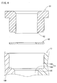
- Apackingplate 80 seals a gap between an outer circumference of the large-diameter portion 32A of the shaft 32 and the inner circumference of the shaft hole 16. More specifically, as shown in FIG. 4, the distal body 13 has a shaft hole large-diameter portion 16D formed by spreading an opening edge of the shaft hole 16 located at the pressure detecting chamber 28 side.
- the large-diameter portion 16D has an inner wall 16M perpendicular to the shaft hole 16.
- the hollow disc-shaped packing plate 80 serving as a sealing member in the invention is provided on the inner wall 16M.
- the packing plate 80 has a smaller inner diameter than a main portion 16H of the centrally open shaft hole 16 of the inner wall 16M.
- the main portion 16H has an open edge in the inner wall 16M.
- the open edge of the main portion 16H is formed with a tapered face 16T.
- a circularly cylindrical bush 81 is force-fitted into the large-diameter portion 16D.
- a packing plate 80 is held between the inner wall 16M and the bush 81.
- the bush 81 includes a pressing protrusion 82 protruding from an inner edge thereof toward the packing plate 80.
- the pressing protrusion 82 is formed into an annular shape and surrounds an overall inner edge of the bush 81 as shown in FIG. 4.
- An outer diameter of the annular portion is gradually decreased as it approaches a distal end of the pressing protrusion 82 into a conical shape.
- the funneled portion of the packing plate 80 is spread by the communication shaft 32 thereby to adhere to the outer circumferential face of the communication shaft 32 (more specifically, the large-diameter portion 32A) , whereby the branch hole 17 and pressure detecting chamber 28 are separated in an airtight manner from each other. Furthermore, even when a fluid pressure in the branch hole 17 is applied to the packing plate 80, the diameter of the funneled portion of the packing plate 80 is reduced such that the funneled portion is pressed against the communication shaft 32 with the result of increase in the airtightness. Consequently, a fluid can reliably be prevented from flowing from the branch hole 17 to the pressure detecting chamber 28.
- the valve element 33 is threadingly engaged with the male thread 32N of the communication shaft 32 as shown in FIG. 2.
- the valve element 33 is formed into a cylindrical shape.
- the valve element 33 has an inner face including an axial half portion formed with a loosely fitted portion 33Y and the other half portion formed with a female thread 33N serving as adj ustingmeans in the invention.
- the loosely fitted portion 33Y is loosely fitted with the male thread 32N of the communication shaft 32 and then, the valve element 33 is turned relative to the communication shaft 32 when the distal end of the communication shaft 32 abuts against the female thread 33N of the valve element 33, whereby the male and female threads 32N and 33N are threadingly engaged with each other .
- a space is defined between the inner face of the valve element 33 and the outer face of the communication shaft 32. The space is closed by a sealing adhesive agent, for example.
- An E-ring 35 is attached to an axially middle of outer periphery of the valve element 33 and projects sidewise.
- a first auxiliary spring 36 is provided between the inner wall of the depression 15B of the distal body 13 and the E-ring 35.
- a second auxiliary spring 37 is provided between the bottom wall 19C of the cap 19 attached to the distal body 13 and the E-ring 35.
- Each of the E-rings 36 and 37 has a conical spring structure in which the E-ring 35 side has a smaller diameter.
- a pressure sensing cylindrical member 42 is fixed to the end thereof located opposite the valve element 33.
- the cylindrical member 42 has an end closed by a bottom wall 42T.
- the end of the communication shaft 32 is fixed to a central outer face of the bottom wall 42T.
- the pressure sensing cylindrical member 42 has the other end located away from the communication shaft 32 and formed with a larger-diameter portion 42D.
- a pair of discs 43A and 43B are accommodated in the pressure sensing cylindrical member 42 and arranged axially.
- a built-in spring 43C is interposed between the discs 43A and 43B so as to be expanded and contracted.
- the disc 43A is disposed so that an outer circumference thereof is normally spaced away from the larger - diameter portion 42D and an inner wall 42P of the pressure sensing cylindrical member 42. Consequently, an amount of movement of the disc 43A to an inner interior of the cylindrical member 42 is limited so that a diaphragm is prevented from excessive flexure as will be described later.
- a flange 42F projects sidewise from an opening edge of the pressure sensing cylindrical member 42.
- the diaphragm 44 is placed on the flange 42F and a fixing disc 45 is further placed on the flange 42F.
- the fixing disc 45 and flange 42F are welded together and the diaphragm 44 is attached to the opening edge of the pressure sensing cylindrical member 42 so as to close an open end 42K.
- the welding is carried out in a vacuum working space. Accordingly, the interior of the cylindrical member 42 closed by the diaphragm 44 is generally vacuum.
- the disc 43A is adherent closely to the diaphragm 44 so that the built-in spring 43C is expanded and contracted with flexure of the diaphragm 44.
- the diaphragm 44 is formed with a plurality of concentric circular ribs giving flexibility to the diaphragm. The circular ribs are shown by reference symbol 44A in FIG. 11 and will be described in detail in a fourth embodiment.
- the fixing disc 45 is made of an annular plate having substantially the same size as the flange 42F.
- the fixing disc 45 includes a cylindrical support wall 45A formed by causing an inner circumferential edge of the annular plate to rise at the side located away from the cylindrical member 42.
- a plunger 46 is fixed to the support wall 45A.
- the plunger 46 is circularly cylindrical and is accommodated inside the solenoid 22 so as to be movable.
- the plunger 46 has an end fitted in the support wall 45A.
- a space is defined between an end of the plunger 46 and the diaphragm 44.
- a plurality of vertical grooves 46T are formed in an outer circumference of the plunger 46. Pressure of a fluid in the pressure detecting chamber 28 is applied via the vertical grooves 46T to diaphragm 44.
- the plunger 46 has a flat end at the terminal wall 24 side.
- the flat end of the plunger 46 has an outer edge formed with a tapered face corresponding to the terminal wall 24.
- a stretching member 50 is inserted inside the plunger 46.
- the stretching member 50 is bar-shaped and has an end provided with a disc 50F which is in abutment with the diaphragm 44 so that the stretching member 50 is moved in the plunger 46 with deformation of the diaphragm 44.
- the plunger 46 has a depression 46Z formed in an end thereof so as to correspond to the disc 50F as shown in FIG. 2.
- the disc 50F is abutted against an inner wall of the depression 46Z thereby to limit the movement stroke of the stretching member 50, whereby the diaphragm 44 is prevented from excessive flexure.
- the stretching member 50 has an end located opposite the diaphragm 44 and set so as to protrude slightly from the end face of the plunger 46 when the diaphragm 44 is flat.
- the pressure control valve 10 is set in an adjusting apparatus (not shown) and a fluid is supplied via the fluid hole 18 into the pressure detecting chamber 28.
- the fluid is also supplied from the branch hole 17 intro the shaft hole 16.
- the valve port 39 is closed by the valve element 33.
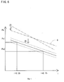
- An excitation current i supplied to the solenoid 22 is changed so that fluid pressure Ps in the pressure detecting chamber 28 is measured when the valve element 33 of the pressure control valve 10 is opened under the condition of each value of excitation current i.
- the linear equation (2) is represented by graph G of FIG. 6.
- a gradient of graph G changes according to a threading engagement position where the valve element 33 is brought into threading engagement with the communication shaft 32. Then, under the condition where the fluid pressure in the branch hole 17 is rendered constant and the excitation current i supplied to the solenoid 22 is set at 0.25 or 0.75 A, the fluid pressure Ps in the pressure detecting chamber 28 is measured when the valve element 33 of the pressure control valve 10.
- a gradient A (A in equation (2)) of graph G as shown in FIG. 6 is obtained from the results.
- the aforesaid threading engagement position is adjusted so that the gradient value A becomes a predetermined set value (required value).
- the pressure control valve 10 of the embodiment is disposed in a refrigerant flow passage 70 of an air conditioner as shown in FIG. 2, for example. More specifically, the air conditioner is provided with a valve insertion hole (not shown) as well as with an adjusting device. The pressure control valve 10 is inserted into the valve insertion hole to be assembled. Since the pressure control valve 10 has such a structure that the connector 21 stands at the side opposite to the valve element 33, the pressure control valve 10 can be inserted into the valve insertion hole without interference of the connector 21 with an inner wall of the valve insertion hole.
- a fluid supply passage 92, a fluid discharge passage 93 and a control flow passage 94 of the flow passage 70 are open in an inner wall of the valve insertion hole.
- the fluid discharge passage 93 communicates with a space inside the cap 19.
- the fluid supply passage 92 communicates with the branch hole 17.
- the control flow passage 94 communicates with the pressure detecting chamber 28.
- the flow passage 70 includes a circulation flow passage 99 through which a refrigerant can be circulated.
- the flow passage 70 further includes an evaporator 97, a condenser 95 and a compressor 96 all provided in the middle of the circulation flow passage 99.
- the pressure control valve 10 of the invention is incorporated in the compressor 96.
- the control flow passage 94 branches off a part of the circulation flow passage 99 between the compressor 96 and the evaporator 97.
- the fluid supply passage 92 branches off a part of the circulation flow passage 99 between the condenser 95 and the compressor 96.
- the fluid discharge passage 93 is connected via an orifice to the flow passage 70.
- the valve element 33 is closed when the fluidpressure Ps in the pressure detecting chamber 28 is higher than a predetermined reference pressure.
- the valve element 33 is opened when the fluid pressure Ps in the pressure detecting chamber 28 is lower than the reference pressure. More specifically, the fluid pressure Ps in the pressure detecting chamber 28 is applied to the diaphragm 44 such that the latter is elastically deformed.
- both ends of the stretching member 50 abut against the terminal wall 24 and the diaphragm 44 respectively as shown in FIG. 2.
- the valve element 33 is pressed against the edge of the valve port 39 by the sucking force of the terminal wall 24 and the plunger 46 and by spring force of the auxiliary spring 36, so that the valve port 39 is closed.
- the diaphragm 44 is used as the pressure sensing member less expensive than the bellows in order that the valve element 33 maybe controlled so as to be opened and closed. Moreover, the terminal wall 24 and the diaphragm 44 are spaced away from each other while the valve port 39 is closed by the valve element 33. Even if a distance between the terminal wall 24 and the diaphragm 44 differs from one case to another for the assembly's sake, the distance between the terminal wall 24 and the diaphragm 44 is changed by the male and female threads 32N and 33N of the communication shaft 32 and the valve element 33 respectively, so that the spring force of the diaphragm 44 against the stretching member 50 can be adjusted. This can reduce the variations in the correspondence relation between the fluid pressure Ps and opening and closure of the valve element 33. Consequently, the valve element can be controlled by the use of the diaphragm 44 with the same accuracy as that by the use of bellows.
- the diaphragm 44 and the pressure sensing cylindrical member 42 are disposed in a space defined between the solenoid 22 and the distal body 13. Accordingly, the size of the diaphragm 44 can be determined without consideration of the inner diameter of the solenoid 22. Furthermore, the plunger 46 is formed into a cylindrical shape, and the stretching member 50 is inserted through the central part of the plunger 46. As a result, the stretching member 50 can stably be moved.
- the built-in spring 43C is compressed between the bottom wall 42T of the pressure sensing cylindrical member 42 and the diaphragm 44. Consequently, an amount of deformation of the diaphragm 44 can be set at a desired value relative to the fluid pressure in the pressure detecting chamber 28.
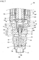
- FIG. 7 illustrates a second embodiment of the invention.
- the valve element 53 and the communication shaft 51 are formed integrally with each other, and the pressure sensing cylindrical member 42 and the communication shaft 51 are discrete from each other.
- the male thread 51N formed on one end of the communication shaft 51 is brought into threading engagement with the female thread 52N formed in the bottom wall 42T of the pressure sensing cylindrical member 42.
- Each of the male and female threads 51N and 52N serves as adjusting means in the invention.
- the second embodiment differs from the first embodiment in the above-described respects. Only the difference between the first and second embodiments will be described in detail later. Identical or similar parts in the second embodiment are labeled with the same reference symbols as those in the second embodiment, and the description of these parts will be eliminated.
- the pressure sensing cylindrical member 42 includes a bottom protrusion 52 protruding from the central inner face of the bottom wall 42T toward the diaphragm 44.
- the built-in spring 43C is fitted with the bottom protrusion 52.
- the bottom wall 42T has a female thread 52N formed in the central outer face thereof (underside as viewed in FIG. 7).
- the female thread 52N extends along the center of the bottom protrusion 52 and is open only to the outer face of the bottom wall 42T.
- the distal end side of the bottom protrusion is closed.
- the bottom wall 42T further has a circular depression 52M with the centrally located female thread 52N.
- the communication shaft 51 includes a smaller-diameter portion 32B , larger-diameter portion 32A, male thread 51N arranged sequentially from the valve element 53 side.
- the male thread 51N has substantially the same diameter as the smaller-diameter portion 32B.
- the larger-diameter portion 32A has both tapered ends continuous to the smaller-diameter portion 32B and male thread 51N respectively.
- the male thread 51N is in threading engagement with the female thread 52N of the pressure sensing cylindrical member 42.
- the side of the valve element 53 spaced away from the communication shaft 51 has a distal end formed with a tool groove 53Mwith which a tool such as a screwdriver is engageable.
- the communication shaft 51 is inserted through the shaft hole 16 of the distal body 13 before the distal and proximal ends are engaged with each other.
- an adhesive agent is applied to the male thread 51N of the communication shaft 51 and subsequently, the male thread 51N is brought into threading engagement with the female thread 52N of the pressure sensing cylindrical member 42.
- the adhesive agent overflowed the female thread 52N is collected in the depression 52M.
- the distal and proximal bodies 13 and 20 are fitted with each other.
- a tool (not shown) is then inserted into a fluid introducing hole 18 to prevent the pressure sensing cylindrical member 42 from turning.
- a depth of threading engagement of the male and female threads 51N and 52N is changed before the adhesive agent hardens, whereby the distance between the terminal wall 24 (see FIG. 1) and the diaphragm 44.
- the spring force of the diaphragm 44 against the stretching member 50 is adjusted. This can reduce the variations in the correspondence relation between the fluid pressure Ps and opening and closure of the valve element 33. Consequently, the valve element can be controlled by the use of the diaphragm 44 with the same accuracy as that by the use of bellows.
- FIG. 8 shows a third embodiment of the invention.
- the third embodiment differs from the first and second embodiments in the structure of the communication shaft 62. Only the difference of the third embodiment from the first and second embodiments will be described in detail later. Identical or similar parts in the third embodiment are labeled with the same reference symbols as those in the first and second embodiments, and the description of these parts will be eliminated.
- a first communication shaft component 60 extends from the pressure sensing cylindrical member 42 to the middle interior of the shaft hole 16.
- the first component 60 has a distal end formed with a female thread 60N serving as adjusting means in the invention.
- a second communication shaft component 61 extends from one end of the valve element 53 to the middle interior of the shaft hole 16.
- the second component 61 has a distal end formed with a male thread 61N serving as adjusting means in the invention.
- an adhesive agent is applied to the male thread 61N of the second communication shaft component 61 before the distal and proximal bodies 13 and 20 are fitted with each other.
- the first and second communication shaft components 60 and 61 are inserted into both ends of the shafthole 16 respectively.
- Themale and female threads 61N and 60N are then brought into threading engagement with each other in the shaft hole 16. Consequently, the first and second communication shaft components 60 and 61 are connected to each other into the communication shaft 62.
- the adhesive agent overflowed the female thread 52N is collected in a stepped portion between the first and second communication shaft components 60 and 61.
- the distal and proximal bodies 13 and 20 are fitted with each other.
- the tool (not shown) is then inserted into the fluid introducing hole 18 to prevent the pressure sensing cylindrical member 42 from turning.
- the depth of threading engagement of the male and female threads 61N and 60N is changed before the adhesive agent hardens, whereby the distance between the terminal wall 24 (see FIG. 1) and the diaphragm 44.
- the spring force of the diaphragm 44 against the stretching member 50 is adjusted. This can reduce the variations in the correspondence relation between the fluid pressure Ps and opening and closure of the valve element 33. Consequently, the valve element can be controlled by the use of the diaphragm 44 with the same accuracy as that by the use of bellows.
- FIGS. 9 to 12 illustrate a fourth embodiment of the invention. Only the difference between the first and fourth embodiments will be described in detail later. Identical or similar parts in the fourth embodiment are labeled with the same reference symbols as those in the first embodiment, and the description of these parts will be eliminated.
- the distal end of the pressure control valve 100 is provided with the cap 19 corresponding to a distal guide in the invention, as shown in FIG. 9.
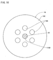
- the cap 19 has a bottom wall 19C formed with a guide hole 119D through which the distal end of the communication shaft 32 extends. Furthermore, the bottomwall 19C has a plurality of fluid pass holes 19B formed therethrough around the guide hole 119D.
- the pressure control valve 100 includes the diaphragm 44 as in each of the foregoing embodiments.
- FIG. 11 shows, in exaggeration, a plurality of concentric circular folds or depressions 44A formed on the diaphragm 44.
- a central part of the diaphragm 44 is vertically displaced with changes in the shape of the folds 44A.
- Each circular fold 44A has a centrally located semicircular expansion 44C formed so as to expand semicircularly toward the inside of the pressure sensing cylindrical member 42. Furthermore, an inner adhering disc 63 and a bottom adhering disc 64 are accommodated in the pressure sensing cylindrical member 42 as shown in FIG. 9.
- the inner adhering disc 63 has embosses formed on an upper side and an underside thereof respectively.
- the bottom adhering disc 64 has an emboss only on the upper side thereof.
- the inner adhering disc 63 is applied to the diaphragm 44, whereas the bottom adhering disc 64 is applied to the bottom of the pressure sensing cylindrical member 42.
- a built-in spring 43C is interposed between the inner and bottom adhering discs 63 and 64 in a compressed state. As a result, an upper side of the inner adhering disc 63 is adherent to the inside of the diaphragm 44.
- the diaphragm 44 has a central abutment 44D formed on a
- the inner adhering disc 63 includes a face adherent to the diaphragm 44 as shown in FIG. 11.
- the face adherent to the diaphragm 44 is formed with a semi-circular depression 63A.
- the semi-circular expansion 44C is placed on the inside of the semi-circular depression 63A, whereupon a centering depression 44B is formed.
- the plunger 46 of the pressure control valve 100 has a larger-diameter portion 46T formed on an end thereof located away from the cylindrical member 42, as shown in FIG. 9.
- the larger-diameter portion 46T has a slightly larger outer diameter.
- the larger-diameter portion 46T is can be brought into sliding contact with the inner face of the guide cylinder 26.
- the movable shaft 30 comprises the pressure sensing cylindrical member 42, the plunger 46 and the communication shaft 32.
- the movable shaft 30 has both ends guided by the guide hole 119D of the cap 19 and the guide cylinder 26 respectively thereby to be moved.
- the plunger 46 includes an end face at the fixed disc 45 side.
- a radially extending groove 46M is formed in the end face.
- the groove 46 has both ends open to the outer face of the plunger 46. Consequently, the fluid pressure in the pressure detecting chamber 28 is also adapted to be applied to the outer face of the diaphragm 44.
- the stretching member 50 includes a stepped slender fixing shaft 50B which is formed on the proximal end thereof.
- the fixing shaft 50B is fitted into the fixing hole 24A formed in the terminal wall 24 to be fixed in the fixing hole.
- the centering protrusion 50A is formed on the distal end of the stretching member 50 so as to protrude therefrom.
- the centering protrusion 50A has such a semi-circular shape as to correspond to the centering depression 44B.
- the stretching member 50 is abutted against the central abutment portion 44D of the diaphragm 44 in the process of assembly of the pressure control valve 100.
- a dimensional error of each component sometimes de-centers the stretching member 50 and the diaphragm 44, as shown in FIG. 12.
- the stretching member 50 is guided by the guide of the outer face of the centering protrusion 50A and the inner face of the centering depression 44B to be positioned at the center of the circular rib 44A of the diaphragm 44.
- the diaphragm 44 and the stretching member 50 are centered by the centering protrusion and depression 50A and 448. Accordingly, an axial force is applied to the center of the circular rib 44A such that the circular rib is deformed uniformly over the circumference, whereupon the spring force of the diaphragm 44 is rendered stable. Consequently, the valve port 39 is opened and closed stably by the valve element 39.
- the stretching member 50 is positioned at the center of the circular rib 44A of the diaphragm 44 by the centering protrusion 50A and the centering depression 44B. Accordingly, the axial force is applied to the center of the circular rib 44A such that the circular rib is deformed uniformly over the circumference, whereupon the spring force of the diaphragm 44 is rendered stable. Consequently, the valve port 39 is opened and closed stably by the valve element 39.
- the movable shaft 30 includes the pressure sensing cylindrical member 42, communication shaft 32 and plunger 46. Both ends of the movable shaft 30 is guided by the guide cylinder 26 and the guide hole 119D of the cap 19 so as to be movable. As a result, an inclination of the movable shaft 30 is limited and accordingly, the resistance due to the sliding contact during the movement thereof is restrained and stabilized. Consequently, the valve port 39 is opened and closed further stably by the valve element 39.
- both outer face of the centering protrusion 50A and inner face of the centering depression 44B are generally semi-circular.
- the strength of the diaphragm 44 can be increased since the inner adhering disc 63 is adhered to the inner face of the diaphragm.
- the distance between the terminal wall 24 and the diaphragm 44 is changed by the male and female threads 32N and 33N of the communication shaft 32 and the valve element 33 respectively, so that the spring force of the diaphragm 44 against the stretching member 50 can be adjusted.
- This can reduce the variations in the correspondence relation between the fluid pressure Ps and opening and closure of the valve element 33. Consequently, the valve element can be controlled by the use of the diaphragm 44 with the same accuracy as that by the use of bellows.
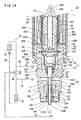
- FIG. 14 illustrates a fifth embodiment of the invention.
- the fifth embodiment differs from the fourth embodiment in that the outer adhering disc 65 is fixed to the central outer face of the diaphragm 44. Only the difference between the fourth and fifth embodiments will be described in detail later. Identical or similar parts in the fifth embodiment are labeled with the same reference symbols as those in the fourth embodiment, and the description of these parts will be eliminated.
- the outer adhering disc 65 is fixed to the central outer face of the diaphragm 44, for example, by an adhesive agent, whereby a central abutment in the invention is constructed.
- a semi-spherical centering depression 65A is formed in an upper face of the outer adhering disc 65.
- the centering protrusion 50A of the stretching member 50 is butted against the centering depression 65A.
- the diaphragm 44 is interposed between the outer and inner adhering discs 65 and 63.
- the outer adhering disc 65 has an underside provided with a convex engagement portion 65B which is brought into concavo-convex engagement with the semi-spherical depression 63A of the inner adhering disc 63.
- a semi-spherical expansion 44C is interposed between the semi-spherical depression 63A and the convex engagement portion 65B.
- the outer adhering disc 65 is adhered to the outer face of the diaphragm 44 thereby to construct the central abutment. Accordingly, the diaphragm 44 can be reinforced. Furthermore, the semi-spherical concave depression 63A of the inner adhering disc 63 is in concavo-convex engagement with the convex engagement portion 65B of the outer adhering disc 65 with the diaphragm 44 being interposed therebetween. Consequently, the accuracy can be improved in the assembly of the outer adhering disc 65 and the diaphragm 44.
- the depth of force-fitting of the fitting portions 13K and 25K may be changed so that the distance between the terminal wall 24 and the diaphragm 44 is adjusted.
- the stretching member 50 is caused to come close to and depart away from the terminal wall 24.
- the stretching member 50 may be caused to come close to and depart away from the diaphragm 44 and may be integral with the terminal wall 24, instead.
- valve port 39 is closed when the diaphragm 44 is flat.
- valve port 39 may be closed when the diaphragm 44 is expanded or depressed, instead.
- the stretching member 50 is provided with the centering protrusion 50A and the diaphragm 44 side is provided with the centering depression 44B or 65A.
- the distal end of the stretching member may be depressed into a semi-spherical shape thereby to be formed into a centering depression and a tapered centering protrusion may protrude from the central portion of the diaphragm, instead.
- the inner adhering disc 63 and/or outer adhering disc 65 may be adhered.
- the single diaphragm 44 may be abutted against the stretching member 50, instead.
- stretching member 50 is assembled to the terminal wall 24 to be fixed.
- the stretching member may be formed integrally on the terminal wall, instead.
Landscapes
- Engineering & Computer Science (AREA)
- Physics & Mathematics (AREA)
- General Engineering & Computer Science (AREA)
- Fluid Mechanics (AREA)
- Mechanical Engineering (AREA)
- General Physics & Mathematics (AREA)
- Automation & Control Theory (AREA)
- Control Of Fluid Pressure (AREA)
- Safety Valves (AREA)
Abstract
Description
| Fluid pressure in the | Ps |
| Fluid pressure in the | Pd |
| Fluid pressure outside the | Pc |
| Cylinder area of the | S1 |
| Diameter of larger- | S2 |
| Diameter of smaller- | S2' |
| Inner diameter of | S3 |
| Spring force of built-in | f1 |
| Spring force of first | f2 |
| Spring force of second | f3 |
Claims (17)
- A pressure control valve including a body (11) to which a valve element (33, 53) is assembled so as to be movable and which is provided with a pressure detecting chamber (28) , wherein the valve element (33, 53) opens a valve port (39) when pressure (Ps) of a fluid provided in the pressure detecting chamber (28) is lower than a predetermined reference pressure, and the valve element (33, 53) closes the valve port (39) when the fluidpressure (Ps) in the pressure detecting chamber (28) is higher than the predetermined reference pressure, characterized by:a shaft hole (16) formed through a wall surrounding the pressure detecting chamber (28) of the body (11) , the shaft hole (16) being provided with the valve port (39) located at a side away from the pressure detecting chamber (28);a communication shaft (32, 51, 62) inserted through the shaft hole (16) and having an end protruding from the valve port (39) and provided with the valve element (33, 53);biasing means (22, 37, 46) for biasing the valve element (33, 53) so that the valve element (33, 53) is pressed against an opening edge of the valve port (39) thereby to close the valve port (39);a branch hole (17) branched from a middle portion of the shaft hole (16) and communicating with the valve port (39);asealingmember (80) sealing a gap between the communication shaft (32, 51, 62) and an inner wall of the shaft hole (16) , said inner wall being located nearer to the pressure detecting chamber (28) than the branch hole (17);a pressure sensing cylindrical member (42) having a closed end fixed to the communication shaft (32, 51, 62) in the pressure detecting chamber (28) and an open end (42K) directed opposite the valve element (33, 53);a diaphragm (44) provided on the open end (42K) of the pressure sensing cylindrical member (42);a terminal wall (24) provided on the body (11) so as to be opposed to the diaphragm (44); anda stretching member (50) stretched between the diaphragm (44) and the terminal wall (24) , the stretching member (50) being subjected to a spring force the diaphragm (44) receives when the fluid pressure (Ps) in the pressure detecting chamber (28) is lower than the predetermined reference pressure, thereby moving the valve element (33, 53) to the opening side.
- A pressure control valve (10, 90,91, 100, 101) of claim 1, further characterized by adjusting means (13K, 25K, 32N, 33N, 51N, 52N, 60N, 61N) for adjusting a distance between the terminal wall. (24) and the diaphragm (44) when the valve port (39) is closed by the valve element (33, 53).
- A pressure control valve of claim 2, characterized in that the valve element (33) is cylindrical and includes a female thread (33N) provided in an inner wall thereof, the communication shaft (32) includes a male thread (32N) provided on an outer wall thereof, and the female and male threads (33N, 32N) serve as the adjusting means (33N, 32N) and are brought into threading engagement with each other.
- A pressure control valve of claim 2, characterized in that the pressure sensing cylindrical member (42) and the communication shaft (51) are discrete from each other and include female and male threads (51N, 52N) serving as the adjusting means (51N, 52N) brought into threading engagement with each other, respectively.
- Apressure control valve of claim2, further characterized by a first communication shaft constituent (60) constituting a part of the communication shaft (62) and extending from the pressure sensing cylindrical member (42) to a middle interior of the shaft hole (16) , a second communication shaft constituent (61) constituting another part of the communication shaft (62) and formed integrally with the valve element (53) so as to extend to a middle interior of the shaft hole (16) , and male and female threads (60N, 61N) provided on the first and second communication shaft constituents (60, 61) and serving as the adjusting means (60N, 61N) brought into threading engagement with each other, respectively.
- A pressure control valve of any one of claims 2 to 5, characterized in that the body (11) is divided and the adjusting means (13K, 25K) comprises a fitting portion (13K, 25K) force-fitted into a divided portion.
- A pressure control valve of any one of claims 1 to 6, characterized in that the biasing means (22, 46) comprises a solenoid (22) which is cylindrical and is fixed to the body (11) , and a plunger (46) inserted into the solenoid (22) , the terminal wall (24) is disposed on one end of the solenoid (22) to constitute a magnetic path for the solenoid (22), the terminal wall (24) serving as an attracting element (24) attracting the plunger (46) , the plunger (46) has both open ends and is cylindrical and is fixed to the pressure sensing cylindrical member (42) while one of the ends thereof is opposed to the diaphragm (44) , the stretching member (50) is inserted through the plunger (46) so as to be movable.
- A pressure control valve of claim 7, characterized in that the body (11) is inserted into a counter-member axially with respect to the solenoid (22) to be assembled to the counter-member and the solenoid (22) includes a connector (21) standing from an end of the solenoid (22) to supply electric power to the solenoid (22).
- A pressure control valve of claim 7 or 8, characterized in that the body (11) includes a proximal end guide (26) provided therein for guiding the plunger (46) in a direction of movement of the plunger (46) and a distal end guide (19) provided therein for guiding the communication shaft (32) in the direction of movement of the plunger (46) , the communication shaft (32) having a distal end passed through the distal end guide (19).
- A pressure control valve of any one of claims 1 to 9, characterized in that the pressure sensing cylindrical member (42) includes a built-in spring (43C) disposed therein so as to be compressed between a bottom (42T) thereof and the diaphragm (44) .
- A pressure control valve of any one of claims 1 to 10, characterized in that the shaft hole (16) includes a larger-diameter portion (16D) formed by spreading an opening edge thereof at the pressure detecting chamber (28) side; the sealing member (80) comprises a hollow, disc-shaped packing plate (80) provided on an inner wall (16M) of the pressure detecting chamber (28) , and further characterized by a cylindrical bush (81) fitted in the larger-diameter portion (16D) of the shaft hole (16) to hold the packing plate (80) between it and an inner wall (16M) of the larger-diameter portion (16D) of the shaft hole (16) and a pressing protrusion (82) protruding from a distal end inner edge of the bush (81) to press an inner edge of the packing plate (80) thereby to deform the inner edge of the packing plate (80) into a funneled shape, the packing plate (80) having an inner edge adhered to an outer circumferential face of the communication shaft (32, 51, 62).
- A pressure control valve of claim 1, characterized in that the diaphragm (44) includes a circular rib (44A) formed thereon and a central abutment portion (44D, 65) provided on a central portion of the rib (44A) so that the stretching member (50) is abutted against the abutment portion (44D, 65) , either one of the stretching member (50) and the central abutment portion (44D, 65) includes a tapered centering protrusion (50A) , the other of the stretching member (50) and the central abutment portion (44D, 65) includes a centering depression (44B, 65A) receiving and guiding the centering protrusion (50A) so that a central axis of the stretching member (50) is aligned with a center of the diaphragm (44).
- A pressure control valve of claim 12, characterized in that the centering protrusion (50A) has an outer face and the centering depression (44B, 65A) has an inner face and the outer face of the centering protrusion (50A) and/or the inner face of the centering depression (44B, 65A) is formedwith a substantially semi-spherical face.
- Apressure control valve of claim 12 or 13, characterized in that the pressure sensing cylindrical member (42) accommodates therein an inner adhering disc (63) adhering to the inner face of the diaphragm (44) and constituting the central abutment portion (44D) together with the diaphragm (44), and the inner adhering disc (63) further includes a portion adherent to the diaphragm (44) and including a part thereof depressed together with the diaphragm (44), said part constituting the centering depression (44B).
- A pressure control valve of any one of claims 12 to 14, further characterized by an outer adhering disc (65) adhering to the outer face of the diaphragm (44) and constituting the central abutment portion (65) together with the diaphragm (44) , the outer adhering disc (65) having the centering depression (65A).
- A pressure control valve of claim 15, characterized in that the pressure sensing cylindrical member (42) accommodates therein an inner adhering disc (63) adhering to the inner face of the diaphragm (44) with the diaphragm (44) being interposed between the inner and outer adhering discs (63, 65) , and the inner and outer adhering discs (63, 65) include concavo-convex engagement portions (63A, 65B) provided in the inner and outer adhering discs (63, 65) engaging each other in a concavo-convex manner with the diaphragm (44) being interposed therebetween.
- A pressure control valve of any one of claims 12 to 16, characterized in that the terminal wall (24) has a fixing hole (24A) in which a proximal end of the stretching member (50) is fitted thereby to be fixed.
Applications Claiming Priority (2)
| Application Number | Priority Date | Filing Date | Title |
|---|---|---|---|
| JP2003349036 | 2003-10-08 | ||
| JP2003349036 | 2003-10-08 |
Publications (3)
| Publication Number | Publication Date |
|---|---|
| EP1522728A2 true EP1522728A2 (en) | 2005-04-13 |
| EP1522728A3 EP1522728A3 (en) | 2006-01-18 |
| EP1522728B1 EP1522728B1 (en) | 2007-07-11 |
Family
ID=34309230
Family Applications (1)
| Application Number | Title | Priority Date | Filing Date |
|---|---|---|---|
| EP04023615A Expired - Lifetime EP1522728B1 (en) | 2003-10-08 | 2004-10-04 | Pressure control valve |
Country Status (5)
| Country | Link |
|---|---|
| US (1) | US6994313B2 (en) |
| EP (1) | EP1522728B1 (en) |
| KR (1) | KR100564723B1 (en) |
| CN (1) | CN1605780A (en) |
| DE (1) | DE602004007451T2 (en) |
Cited By (5)
| Publication number | Priority date | Publication date | Assignee | Title |
|---|---|---|---|---|
| CN106124128A (en) * | 2016-08-20 | 2016-11-16 | 无锡鹰贝精密轴承有限公司 | Valve core gas tightness detecting device |
| CN106248317A (en) * | 2016-08-20 | 2016-12-21 | 无锡鹰贝精密轴承有限公司 | Spool air-tightness detection method |
| EP3181903A1 (en) * | 2015-12-16 | 2017-06-21 | Fujikoki Corporation | Variable-capacity compressor control valve |
| CN111853056A (en) * | 2019-04-30 | 2020-10-30 | 美蓓亚三美株式会社 | Radial guide |
| CN113219498A (en) * | 2021-04-30 | 2021-08-06 | 杭州海悦软件有限公司 | GPS empty disk detection device |
Families Citing this family (11)
| Publication number | Priority date | Publication date | Assignee | Title |
|---|---|---|---|---|
| JP4453732B2 (en) * | 2007-09-14 | 2010-04-21 | 株式会社デンソー | solenoid valve |
| KR100927896B1 (en) * | 2007-09-19 | 2009-11-25 | 주식회사 세 바 | Fluid control valve |
| EP2499404B1 (en) * | 2009-11-09 | 2018-08-01 | Goyen Controls Co Pty Ltd. | Diaphragm |
| JP5424397B2 (en) * | 2009-12-04 | 2014-02-26 | サンデン株式会社 | Control valve and swash plate type variable capacity compressor with control valve |
| CN101956867B (en) * | 2010-06-08 | 2013-04-03 | 昆山新莱洁净应用材料股份有限公司 | Diaphragm seal device for reciprocating type valve rod |
| CN104213187B (en) * | 2014-08-21 | 2016-09-28 | 杭州慧翔电液技术开发有限公司 | A kind of vacuum detecting protection device |
| JP6616998B2 (en) * | 2015-10-15 | 2019-12-04 | Toyo Tire株式会社 | Tire holding device |
| JP6600603B2 (en) * | 2016-06-28 | 2019-10-30 | 株式会社不二工機 | Control valve for variable displacement compressor and assembly method thereof |
| WO2019093166A1 (en) * | 2017-11-07 | 2019-05-16 | 株式会社不二工機 | Control valve for variable displacement compressor |
| CN112138729B (en) * | 2019-06-26 | 2025-03-18 | 京东方科技集团股份有限公司 | Sampling structure, sealing structure and detection components |
| CN110763395A (en) * | 2019-10-30 | 2020-02-07 | 南京高华科技股份有限公司 | Pressure measuring device |
Family Cites Families (14)
| Publication number | Priority date | Publication date | Assignee | Title |
|---|---|---|---|---|
| JP2943934B2 (en) * | 1990-03-20 | 1999-08-30 | サンデン株式会社 | Variable capacity swash plate compressor |
| JP3410761B2 (en) | 1993-04-19 | 2003-05-26 | 株式会社豊田自動織機 | Swash plate type variable displacement compressor and control method thereof |
| JPH0743543A (en) | 1993-07-29 | 1995-02-14 | Furukawa Electric Co Ltd:The | Optical fiber line switching device |
| DE4328709C2 (en) * | 1993-08-26 | 1996-04-04 | Bosch Gmbh Robert | Solenoid valve |
| JP3627338B2 (en) * | 1995-12-30 | 2005-03-09 | アイシン・エィ・ダブリュ株式会社 | Pressure regulating valve in hydraulic control device of automatic transmission |
| JP3435077B2 (en) * | 1998-09-16 | 2003-08-11 | 株式会社鷺宮製作所 | Bellows pressure operated valve |
| DE19904901A1 (en) * | 1999-02-06 | 2000-08-10 | Zahnradfabrik Friedrichshafen | Proportional pressure control valve |
| DE19904902A1 (en) * | 1999-02-06 | 2000-08-10 | Zahnradfabrik Friedrichshafen | Proportional pressure control valve |
| JP2000249051A (en) * | 1999-03-01 | 2000-09-12 | Toyota Autom Loom Works Ltd | Control valve for variable displacement swash plate type compressor |
| JP3886290B2 (en) * | 1999-04-27 | 2007-02-28 | 株式会社テージーケー | Capacity control device for variable capacity compressor |
| JP4205826B2 (en) * | 1999-11-30 | 2009-01-07 | 株式会社不二工機 | Control valve for variable displacement compressor |
| JP2001311477A (en) | 2000-04-28 | 2001-11-09 | Nok Corp | Solenoid valve |
| JP4366835B2 (en) * | 2000-05-26 | 2009-11-18 | アイシン精機株式会社 | solenoid valve |
| US6746214B2 (en) * | 2001-03-01 | 2004-06-08 | Pacific Industrial Co., Ltd. | Control valve for compressors and manufacturing method thereof |
-
2004
- 2004-10-04 DE DE602004007451T patent/DE602004007451T2/en not_active Expired - Lifetime
- 2004-10-04 EP EP04023615A patent/EP1522728B1/en not_active Expired - Lifetime
- 2004-10-06 KR KR1020040079375A patent/KR100564723B1/en not_active Expired - Fee Related
- 2004-10-06 US US10/959,538 patent/US6994313B2/en not_active Expired - Fee Related
- 2004-10-08 CN CNA2004100849791A patent/CN1605780A/en active Pending
Cited By (7)
| Publication number | Priority date | Publication date | Assignee | Title |
|---|---|---|---|---|
| EP3181903A1 (en) * | 2015-12-16 | 2017-06-21 | Fujikoki Corporation | Variable-capacity compressor control valve |
| US10578087B2 (en) | 2015-12-16 | 2020-03-03 | Fujikoki Corporation | Variable-capacity compressor control valve |
| CN106124128A (en) * | 2016-08-20 | 2016-11-16 | 无锡鹰贝精密轴承有限公司 | Valve core gas tightness detecting device |
| CN106248317A (en) * | 2016-08-20 | 2016-12-21 | 无锡鹰贝精密轴承有限公司 | Spool air-tightness detection method |
| CN111853056A (en) * | 2019-04-30 | 2020-10-30 | 美蓓亚三美株式会社 | Radial guide |
| CN113219498A (en) * | 2021-04-30 | 2021-08-06 | 杭州海悦软件有限公司 | GPS empty disk detection device |
| CN113219498B (en) * | 2021-04-30 | 2024-04-02 | 浙江盘盘科技有限公司 | GPS empty disc detection device |
Also Published As
| Publication number | Publication date |
|---|---|
| KR20050033825A (en) | 2005-04-13 |
| US6994313B2 (en) | 2006-02-07 |
| CN1605780A (en) | 2005-04-13 |
| EP1522728A3 (en) | 2006-01-18 |
| DE602004007451T2 (en) | 2008-03-13 |
| DE602004007451D1 (en) | 2007-08-23 |
| KR100564723B1 (en) | 2006-03-27 |
| US20050077493A1 (en) | 2005-04-14 |
| EP1522728B1 (en) | 2007-07-11 |
Similar Documents
| Publication | Publication Date | Title |
|---|---|---|
| EP1522728B1 (en) | Pressure control valve | |
| CN102834656B (en) | Balance poppet type solenoid valve | |
| CN113167394B (en) | Diaphragm valve | |
| US20140102568A1 (en) | Fluidic interface valve assembly with elastomeric ferrule device | |
| JP2011043102A (en) | Control valve for variable displacement compressor | |
| US11808367B2 (en) | Valve, device for regulating the pressure of a flow medium using the valve, and device for securing the valve in a transmission component | |
| US6474560B2 (en) | Thermal expansion valve | |
| WO2020170720A1 (en) | Flow control valve and assembly method for same | |
| JP5214660B2 (en) | Fluid control valve | |
| JP5499254B2 (en) | Control valve for variable capacity compressor | |
| JP4414269B2 (en) | Flow rate characteristic adjustment mechanism of electromagnetic proportional valve and flow rate characteristic adjustment method using the same | |
| JP4255892B2 (en) | Expansion valve | |
| US6971629B2 (en) | Control valve and method of making the same | |
| JP2009103116A (en) | Control valve for variable displacement compressor | |
| JP4147211B2 (en) | Pressure regulating valve | |
| JP4401276B2 (en) | Pressure control valve | |
| JP2005133932A (en) | Pressure control valve | |
| WO2024135843A1 (en) | Linkage-type constant-pressure valve | |
| JP2004138228A (en) | Differential pressure valve | |
| US20200173564A1 (en) | Diaphragm valve | |
| JPH10196797A (en) | Seal structure | |
| JP3323813B2 (en) | Sample support device | |
| CN120322636A (en) | Solenoid valve and assembly method of solenoid valve | |
| JPH09229227A (en) | Solenoid | |
| JP2025106173A (en) | Solenoid valve |
Legal Events
| Date | Code | Title | Description |
|---|---|---|---|
| PUAI | Public reference made under article 153(3) epc to a published international application that has entered the european phase |
Free format text: ORIGINAL CODE: 0009012 |
|
| AK | Designated contracting states |
Kind code of ref document: A2 Designated state(s): AT BE BG CH CY CZ DE DK EE ES FI FR GB GR HU IE IT LI LU MC NL PL PT RO SE SI SK TR |
|
| AX | Request for extension of the european patent |
Extension state: AL HR LT LV MK |
|
| PUAL | Search report despatched |
Free format text: ORIGINAL CODE: 0009013 |
|
| AK | Designated contracting states |
Kind code of ref document: A3 Designated state(s): AT BE BG CH CY CZ DE DK EE ES FI FR GB GR HU IE IT LI LU MC NL PL PT RO SE SI SK TR |
|
| AX | Request for extension of the european patent |
Extension state: AL HR LT LV MK |
|
| RIC1 | Information provided on ipc code assigned before grant |
Ipc: F16K 31/06 20060101ALI20051201BHEP Ipc: F04B 27/18 20060101AFI20050223BHEP |
|
| 17P | Request for examination filed |
Effective date: 20060301 |
|
| AKX | Designation fees paid |
Designated state(s): DE FR |
|
| GRAP | Despatch of communication of intention to grant a patent |
Free format text: ORIGINAL CODE: EPIDOSNIGR1 |
|
| GRAS | Grant fee paid |
Free format text: ORIGINAL CODE: EPIDOSNIGR3 |
|
| GRAA | (expected) grant |
Free format text: ORIGINAL CODE: 0009210 |
|
| AK | Designated contracting states |
Kind code of ref document: B1 Designated state(s): DE FR |
|
| REF | Corresponds to: |
Ref document number: 602004007451 Country of ref document: DE Date of ref document: 20070823 Kind code of ref document: P |
|
| ET | Fr: translation filed | ||
| PLBE | No opposition filed within time limit |
Free format text: ORIGINAL CODE: 0009261 |
|
| STAA | Information on the status of an ep patent application or granted ep patent |
Free format text: STATUS: NO OPPOSITION FILED WITHIN TIME LIMIT |
|
| 26N | No opposition filed |
Effective date: 20080414 |
|
| PGFP | Annual fee paid to national office [announced via postgrant information from national office to epo] |
Ref country code: DE Payment date: 20101027 Year of fee payment: 7 |
|
| PGFP | Annual fee paid to national office [announced via postgrant information from national office to epo] |
Ref country code: FR Payment date: 20111103 Year of fee payment: 8 |
|
| REG | Reference to a national code |
Ref country code: FR Ref legal event code: ST Effective date: 20130628 |
|
| PG25 | Lapsed in a contracting state [announced via postgrant information from national office to epo] |
Ref country code: DE Free format text: LAPSE BECAUSE OF NON-PAYMENT OF DUE FEES Effective date: 20130501 |
|
| REG | Reference to a national code |
Ref country code: DE Ref legal event code: R119 Ref document number: 602004007451 Country of ref document: DE Effective date: 20130501 |
|
| PG25 | Lapsed in a contracting state [announced via postgrant information from national office to epo] |
Ref country code: FR Free format text: LAPSE BECAUSE OF NON-PAYMENT OF DUE FEES Effective date: 20121031 |