JP4255892B2 - Expansion valve - Google Patents
Expansion valve Download PDFInfo
- Publication number
- JP4255892B2 JP4255892B2 JP2004207257A JP2004207257A JP4255892B2 JP 4255892 B2 JP4255892 B2 JP 4255892B2 JP 2004207257 A JP2004207257 A JP 2004207257A JP 2004207257 A JP2004207257 A JP 2004207257A JP 4255892 B2 JP4255892 B2 JP 4255892B2
- Authority
- JP
- Japan
- Prior art keywords
- valve body
- expansion valve
- valve
- guide member
- operating rod
- Prior art date
- Legal status (The legal status is an assumption and is not a legal conclusion. Google has not performed a legal analysis and makes no representation as to the accuracy of the status listed.)
- Expired - Fee Related
Links
Images


Classifications
-
- F—MECHANICAL ENGINEERING; LIGHTING; HEATING; WEAPONS; BLASTING
- F25—REFRIGERATION OR COOLING; COMBINED HEATING AND REFRIGERATION SYSTEMS; HEAT PUMP SYSTEMS; MANUFACTURE OR STORAGE OF ICE; LIQUEFACTION SOLIDIFICATION OF GASES
- F25B—REFRIGERATION MACHINES, PLANTS OR SYSTEMS; COMBINED HEATING AND REFRIGERATION SYSTEMS; HEAT PUMP SYSTEMS
- F25B2341/00—Details of ejectors not being used as compression device; Details of flow restrictors or expansion valves
- F25B2341/06—Details of flow restrictors or expansion valves
- F25B2341/068—Expansion valves combined with a sensor
- F25B2341/0683—Expansion valves combined with a sensor the sensor is disposed in the suction line and influenced by the temperature or the pressure of the suction gas
-
- F—MECHANICAL ENGINEERING; LIGHTING; HEATING; WEAPONS; BLASTING
- F25—REFRIGERATION OR COOLING; COMBINED HEATING AND REFRIGERATION SYSTEMS; HEAT PUMP SYSTEMS; MANUFACTURE OR STORAGE OF ICE; LIQUEFACTION SOLIDIFICATION OF GASES
- F25B—REFRIGERATION MACHINES, PLANTS OR SYSTEMS; COMBINED HEATING AND REFRIGERATION SYSTEMS; HEAT PUMP SYSTEMS
- F25B2500/00—Problems to be solved
- F25B2500/13—Vibrations
Description
本発明は、カーエアコン等の空調装置に装備されて、冷媒の温度に応じて蒸発器(エバポレータ)へ供給される冷媒の流量を制御する膨張弁に関する。 The present invention relates to an expansion valve that is installed in an air conditioner such as a car air conditioner and controls the flow rate of refrigerant supplied to an evaporator (evaporator) according to the temperature of the refrigerant.
この種の膨張弁は、例えば、下記の特許文献1に開示されている。
ところが、上記特許文献1に開示された従来の膨張弁においては、弁受け部材、スプリング、調節ネジ等、多数の部品点数を要しており、膨張弁の小型化及び軽量化の達成を困難にしていた。
さらには、弁室より調節ネジ部分を通して冷媒の漏れる不具合の生ずるおそれがあった。
However, the conventional expansion valve disclosed in
Furthermore, there is a risk that a refrigerant leaks from the valve chamber through the adjusting screw portion.
かかる点に鑑み、本発明の課題は、カーエアコンの小型化、軽量化の要請に応じ、構造を簡素化し、組立工数を削減した膨張弁を提供することを目的とする。 In view of this point, an object of the present invention is to provide an expansion valve that has a simplified structure and reduced assembly man-hours in response to demands for smaller and lighter car air conditioners.
また、本発明の更なる課題は、シンプルでコストのかからない手段によって、高圧冷媒の圧力変動に対する弁動作の安定を達成することができる膨張弁を提供することを目的とする。 Another object of the present invention is to provide an expansion valve that can achieve stable valve operation against pressure fluctuations of a high-pressure refrigerant by simple and inexpensive means.
また、本発明の更なる課題は、上記課題を達成させた状態で、蒸発器等への取付穴との間隔(肉厚)を確保し、弁本体の腐食を発生させず、冷媒の漏れの惧れのない膨張弁を提供することを目的とする。 Further, according to the present invention, in the state in which the above-mentioned problems are achieved, the space (thickness) between the mounting hole to the evaporator and the like is ensured, the valve body is not corroded, and the refrigerant leaks. An object is to provide an expansion valve without fear.
さらに、本発明の更なる課題は、駆動装置のキャン体の取付座のおねじ部を弁本体の駆動装置取付穴のめねじ部に螺合させることにより、駆動装置が弁本体の駆動装置取付穴に取り付けられ、シール部材が駆動装置のキャン体の取付座の外周に密接し、弁本体の駆動装置取付穴の内周と駆動装置のキャン体の取付座の外周との間からの冷媒の漏れをシール部材により防止することができ、駆動装置のキャン体の取付座のおねじ部を弁本体の駆動装置取付穴のめねじ部に対して締め付ける方向または緩める方向に回転させることで、作動棒を駆動装置と共に上下方向に移動させることができ、駆動装置のキャン体の取付座のおねじ部の弁本体の駆動装置取付穴のめねじ部へのねじ込み量で、弁体が開き始めるセット値の微調整を行うことができる膨張弁を提供することを目的とする。 Furthermore, a further problem of the present invention is that the drive device is attached to the drive device of the valve body by screwing the male screw portion of the mounting seat of the can body of the drive device with the female screw portion of the drive device mounting hole of the valve body. The seal member is in close contact with the outer periphery of the mounting seat of the drive device can body, and the refrigerant from between the inner periphery of the drive device mounting hole of the valve body and the outer periphery of the mounting seat of the drive device can body Leakage can be prevented by the seal member, and it can be operated by rotating the male threaded part of the mounting seat of the can body of the driving device in the tightening or loosening direction relative to the female threaded part of the driving device mounting hole of the valve body. The rod can be moved up and down together with the drive unit, and the valve body starts to open by the amount of screwing of the male thread part of the mounting seat of the can body of the drive unit into the female thread part of the drive unit mounting hole of the valve body You can fine tune the value An object of the present invention is to provide an expansion valve.
本発明は、上記課題を達成するために、下記の手段を講じた。即ち、
請求項1記載の膨張弁は、弁本体と、該弁本体内に形成された有底の弁室と、該弁室から上方に向けて形成されるとともに前記弁本体の上端に開口した開口部と、前記弁本体に形成され前記弁室に高圧冷媒を導入する第1の通路と、前記弁本体に形成され蒸発器側に送出される冷媒が通過する第2の通路と、前記弁本体に形成され前記蒸発器側から送出される冷媒が通過する第3の通路と、前記開口部内に装着され前記弁室から前記第2の通路に向けて流れる冷媒を絞る絞り部を有するオリフィス部と、該絞り部に対向するように前記弁室内に配置された弁体と、前記開口部内に挿入され前記弁体を移動させる作動棒と、前記弁本体の上端に装着され前記作動棒を駆動する駆動装置と、前記開口部内に装着され前記作動棒を摺動自在に案内するガイド部材と、前記ガイド部材に装着され前記作動棒の振動を防止する防振部材とを備え、前記防振部材は、前記作動棒と同心状に配置されるとともに弾性変形可能な円環状の環状部と、該環状部と一体的に形成され前記作動棒の外周面に弾性的に接触する防振バネとからなるものであり、前記弁体、前記オリフィス部、前記ガイド部材、前記作動棒を前記弁本体の上方から前記弁本体内に挿入・装着するようにしたことを特徴とする。
In order to achieve the above object, the present invention has taken the following measures. That is,
The expansion valve according to
請求項2記載の膨張弁は、請求項1記載の膨張弁において、前記オリフィス部が前記ガイド部材に一体的に形成されていることを特徴とする。 The expansion valve according to a second aspect is the expansion valve according to the first aspect, wherein the orifice portion is formed integrally with the guide member .
請求項3記載の膨張弁は、請求項1記載の膨張弁において、前記ガイド部材は、前記弁本体にカシメ固定されていることを特徴とする。 An expansion valve according to a third aspect of the present invention is the expansion valve according to the first aspect, wherein the guide member is fixed by caulking to the valve body .
請求項4記載の膨張弁は、請求項1記載の膨張弁において、前記ガイド部材は、前記ガイド部材を前記弁本体の所定箇所に位置決めするための位置決め部を前記弁本体と協議して構成していることを特徴とする。
Expansion valve according to claim 4, wherein, in the expansion valve according to
請求項5記載の膨張弁は、請求項4記載の膨張弁において、前記位置決め部は、前記ガイド部材に一体的に形成された段部により構成されていることを特徴とする。 According to a fifth aspect of the present invention , in the expansion valve according to the fourth aspect , the positioning portion is constituted by a step portion formed integrally with the guide member .
請求項6記載の膨張弁は、請求項1記載の膨張弁において、前記オリフィス部は、前記弁本体に圧入されていることを特徴とする。 An expansion valve according to a sixth aspect is the expansion valve according to the first aspect , wherein the orifice portion is press-fitted into the valve body .
請求項7記載の膨張弁は、請求項5記載の膨張弁において、前記段部は、前記弁本体に対してシール性を保持する状態で当接していることを特徴とする。 An expansion valve according to a seventh aspect is the expansion valve according to the fifth aspect , wherein the stepped portion is in contact with the valve main body in a state of maintaining a sealing property .
請求項8記載の膨張弁は、請求項7記載の膨張弁において、前記段部における前記弁本体との当接部は、前記弁本体に面接触していることを特徴とする。 An expansion valve according to an eighth aspect is the expansion valve according to the seventh aspect, wherein a contact portion of the step portion with the valve main body is in surface contact with the valve main body .
請求項9記載の膨張弁は、請求項2記載の膨張弁において、前記ガイド部材を前記弁本体に対して位置決めする位置決め部が、前記オリフィス部と前記弁本体によって構成されていることを特徴とする。 The expansion valve according to claim 9 is the expansion valve according to claim 2 , wherein a positioning portion for positioning the guide member with respect to the valve body is constituted by the orifice portion and the valve body. To do.
請求項10記載の膨張弁は、請求項9記載の膨張弁において、前記位置決め部は、前記弁本体に一体的に形成された段部により構成されていることを特徴とする。 According to a tenth aspect of the present invention , in the expansion valve according to the ninth aspect , the positioning portion is constituted by a step portion formed integrally with the valve body .
請求項11記載の膨張弁は、請求項9又は請求項10に記載の膨張弁において、前記ガイド部材は、前記弁本体にカシメ固定されていることを特徴とする。 An expansion valve according to an eleventh aspect is the expansion valve according to the ninth or tenth aspect , wherein the guide member is caulked and fixed to the valve body .
請求項12記載の膨張弁は、請求項1乃至請求項11のいずれかに記載の膨張弁において、前記防振部材が前記ガイド部材に内装され、前記ガイド部材における前記防振部材を内装する部位の少なくとも一部が前記第3の通路内に配置されていることを特徴とする。 The expansion valve according to a twelfth aspect of the present invention is the expansion valve according to any one of the first to eleventh aspects, wherein the vibration isolating member is internally provided in the guide member, and the vibration isolating member is provided in the guide member. At least a part of which is disposed in the third passage.
請求項13記載の膨張弁は、請求項1乃至請求項12のいずれかに記載の膨張弁において、前記オリフィス部の外周にはシール溝が形成され、該シール溝にはリングシールが装着されていることを特徴とする。 An expansion valve according to a thirteenth aspect is the expansion valve according to any one of the first to twelfth aspects, wherein a seal groove is formed on an outer periphery of the orifice portion, and a ring seal is attached to the seal groove. It is characterized by being.
請求項14記載の膨張弁は、請求項1乃至請求項13のいずれかに記載の膨張弁において、前記開口部は、前記第3の通路に連通するとともに上端が前記駆動装置を取付けるための駆動装置取付穴とされ、該駆動装置取付穴の内周には環状凹溝とめねじ部が形成され、前記駆動装置は前記駆動装置取付穴に固定されるキャン体を有し、該キャン体には前記駆動装置取付穴に嵌合する筒状の取付座が一体に形成され、該取付座の外周には前記めねじ部に螺合するおねじ部が形成され、前記環状凹溝には前記取付座の外周面に密着するシール部材が配置されていることを特徴とする。
The expansion valve according to
請求項15記載の膨張弁は、請求項14記載の膨張弁において、前記シール部材はOリングであることを特徴とする。
また、請求項16記載の膨張弁は、請求項14記載の膨張弁において、前記キャン体内には、前記蒸発器から送出される冷媒の温度を感知して変位するダイアフラムと該ダイアフラムの変位を前記作動棒に伝達するストッパ部材が装備され、前記作動棒の一方の端部が前記ストッパ部材に接続されるとともに前記作動棒の他方の端部の先端が前記弁体に当接されることを特徴とする。
The expansion valve according to
An expansion valve according to a sixteenth aspect is the expansion valve according to the fourteenth aspect , wherein the can body includes a diaphragm that senses and displaces a temperature of a refrigerant delivered from the evaporator, and a displacement of the diaphragm. A stopper member for transmitting to the operating rod is provided, and one end of the operating rod is connected to the stopper member, and the tip of the other end of the operating rod is in contact with the valve body. And
本発明の膨張弁は、以上のように、膨張弁の弁本体に対して、パワーエレメントを取り付ける開口部側から、内径寸法が順次小さくなる開口部を形成し、先端部を有底穴としたものである。
そして、この開口部に弁体やオリフィス部を一体に有するガイド部材を圧入或いは嵌合して作動棒を案内させ、冷媒の高圧側と低圧側の絞り部を区画する構成としたものである。
この構成により、膨張弁の部品点数を削減し組立工数を減ずることができ、また、オリフィス部を一体に有するガイド部材を圧入或いは嵌合し、且つ、カシメ固定することで、ガイド部材の位置決めと共に冷媒の漏れを防止することができる。
As described above, the expansion valve of the present invention forms an opening having a smaller inner diameter dimension from the opening side where the power element is attached to the valve body of the expansion valve, and has a bottomed hole at the tip. Is.
Then, a guide member integrally having a valve body and an orifice portion is press-fitted or fitted into the opening portion to guide the operating rod, and the high pressure side and the low pressure side throttle portion of the refrigerant are partitioned.
With this configuration, the number of parts of the expansion valve can be reduced and the number of assembling steps can be reduced, and the guide member having the orifice part integrally can be press-fitted or fitted and fixed by caulking, thereby positioning the guide member. Leakage of the refrigerant can be prevented.
また、防振部材の配置により、冷媒の圧力変動に伴う膨張弁の弁体振動を抑制することで、弁機能を安定させることができると共に、防振部材は簡単な構成であることから、加工が簡単で弁本体への装着も容易であり、取り扱い易く有用性の高い膨張弁を実現できる。 In addition, by disposing the vibration isolating member, it is possible to stabilize the valve function by suppressing the vibration of the expansion valve accompanying the pressure fluctuation of the refrigerant, and the vibration isolating member has a simple configuration. Is easy to mount on the valve body, and an expansion valve that is easy to handle and highly useful can be realized.
また、リング部材の防振バネを作動棒に点接触するように当接・支持させるから、作動棒が仮に多少傾斜することがあっても、円滑な支持状態が保持される。 In addition, since the vibration isolating spring of the ring member is abutted and supported so as to make point contact with the operating rod, a smooth support state is maintained even if the operating rod is slightly inclined.
また、ガイド部材を圧入する段付穴と蒸発器等への取付穴との間隔(肉厚)を確保することで、弁本体の腐食を発生させず、冷媒の漏れの惧れのない膨張弁とすることができる。 In addition, by securing the distance (thickness) between the stepped hole for press-fitting the guide member and the mounting hole for the evaporator, etc., the valve body does not corrode and there is no risk of refrigerant leakage It can be.
さらに、駆動装置のキャン体の取付座のおねじ部を弁本体の駆動装置取付穴のめねじ部に螺合させることにより、駆動装置が弁本体の駆動装置取付穴に取り付けられ、シール部材が駆動装置のキャン体の取付座の外周に密接し、弁本体の駆動装置取付穴の内周と駆動装置のキャン体の取付座の外周との間からの冷媒の漏れをシール部材により防止することができ、駆動装置のキャン体の取付座のおねじ部を弁本体の駆動装置取付穴のめねじ部に対して締め付ける方向または緩める方向に回転させることで、作動棒を駆動装置と共に上下方向に移動させることができ、駆動装置のキャン体の取付座のおねじ部の弁本体の駆動装置取付穴のめねじ部へのねじ込み量で、弁体が開き始めるセット値の微調整を行うことができる。 Further, by screwing the male thread portion of the mounting seat of the can body of the driving device to the female screw portion of the driving device mounting hole of the valve body, the driving device is attached to the driving device mounting hole of the valve body, and the seal member is A seal member prevents the leakage of refrigerant from the inner periphery of the drive device mounting hole of the valve body and the outer periphery of the drive device mounting body seat of the drive device, in close contact with the outer periphery of the drive device mounting body seat. The operating rod can be moved up and down together with the drive device by rotating the male thread of the mounting seat of the can body of the drive device in the tightening or loosening direction with respect to the female screw portion of the drive device mounting hole of the valve body. It can be moved, and the set value at which the valve body begins to open can be finely adjusted by the amount of screwing of the male thread part of the mounting seat of the can body of the driving device into the female thread part of the driving device mounting hole of the valve body it can.
以下、本発明の実施例を説明する。 Examples of the present invention will be described below.
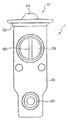
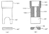
図1は、本発明の実施例1の膨張弁の断面図、図2は、図1の右側面図、図3は、図1のガイド部材の拡大断面図、図4は、図1の要部の拡大断面図、図5は、図1のガイド部材の他の実施例の正面図(A)及び断面図(B)、図6は、図1のガイド部材の更なる他の実施例の正面図(A)及び断面図(B)である。 1 is a cross-sectional view of an expansion valve according to a first embodiment of the present invention, FIG. 2 is a right side view of FIG. 1, FIG. 3 is an enlarged cross-sectional view of a guide member of FIG. 1, and FIG. FIG. 5 is a front view (A) and a sectional view (B) of another embodiment of the guide member of FIG. 1, and FIG. 6 is a further embodiment of the guide member of FIG. It is a front view (A) and sectional drawing (B).
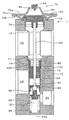
全体を符号1で示す膨張弁は、アルミ合金等でつくられる外面が角柱形状で中心部に円孔を有する弁本体10を有し、弁本体10には、高圧の冷媒が流入する第1の通路20が設けられる。
第1の通路20は、有底22aの弁室22に連通し、弁室22の開口部にガイド部材100と一体に形成されたオリフィス部40が圧入固着される。
また、弁室22内には、球状の弁体30が支持部材32に溶接により取り付けられて配置され、支持部材32は、スプリング34により弁体30を常時オリフィス部40に向けて付勢する。
The expansion valve generally indicated by
The
A
弁本体10に設けられる筒状のガイド部材100は、図3に示すように、その軸芯部に作動棒孔101が形成されるガイド部102と、その外周部には段部110を有し、該段部110を介して一体に形成された円柱状の径大部121と、弁本体10に対してガイド部102の通路43を介して一体に形成されたオリフィス部40とからなり、図1,4に示すように、弁本体10に形成された段部13と、ガイド部材100の段部110とが面接触により当接し、ガイド部材100は正確に位置決めされて固着され、かかる段部110と段部13との面接触によりシール性が確保される。
なお、ガイド部材100の内径部に、リング状のシール部材(図示せず)を挿入し、第2の通路24と第3の通路26との間の冷媒の通過をシールしても良い。
As shown in FIG. 3, the
Note that a ring-shaped seal member (not shown) may be inserted into the inner diameter portion of the
また、図1,4に示すように、第2の通路24に連通するガイド部材100の下部に形成された通路43を介して形成されるオリフィス部40は、中央部に上記弁室22と上記通路43とを連通させる絞り部42を有し、弁体30との間で冷媒の流路を形成する。
オリフィス部40を通過した冷媒は、通路43を経て第2の通路24から図示しない蒸発器側へ送り出される。
蒸発器から戻る冷媒は、第3の通路26を通って図示しない圧縮機側へ送られる。
As shown in FIGS. 1 and 4, the
The refrigerant that has passed through the
The refrigerant returning from the evaporator is sent to the compressor side (not shown) through the
ガイド部102の上部には、図3又は図4に示すように、段付穴14内に配置される径大部121が形成され、その径大孔部120に防振部材50が配置されて作動棒60に装着され、作動棒60の振動を防止する。
更に、径大部121に連続して円柱状のガイド部102が形成され、その中心部に作動棒60が摺動自在に案内され、オリフィス部40の下部周部には下端部外周が径小となる案内部44が形成されている。
かかる構成のガイド部材100のガイド部102側が弁本体10にカシメ固定される。
即ち、ガイド部材100の上端部となる径大部の端部122は、弁本体10側に形成されるカシメ部11(図4参照)により弁本体10にカシメ固定される。
したがって、本実施例のガイド部材100は弁本体10によりカシメ固定されると共に、ガイド部材100のオリフィス部40は圧入により弁本体10に固定されるので、ガイド部材100は弁本体10に確実に固定される。
しかも、オリフィス部40は圧入されることにより、シール性を確保して固定されるのである。
As shown in FIG. 3 or FIG. 4, a
Further, a
The
That is, the large-
Therefore, the
In addition, the
さらに、ガイド部材100は、その段部110により弁本体10に面接触により当接するので、段部110はガイド部材100の固定の際の位置決め部として作用すると共に、その面接触によりシール性を確実に確保することができる。
これにより、第2の通路24より第3の通路26への冷媒の漏れを防止することが可能となる。
かくして、第1の通路20より第2の通路24への冷媒の漏れ及び第2の通路24から第3の通路26への冷媒の漏れを防止することができる。
なお、オリフィス部40の径小となる案内部44は円板部45の円縁部と一体に立設されて形成された壁部44’により構成され、壁部44’に連続する平坦部46及び傾斜部47が絞り部42に接続されている。
この傾斜部47に弁体30が配置されて絞り部42に対向して設けられる。
Further, since the
Thereby, it is possible to prevent the refrigerant from leaking from the
Thus, the refrigerant leakage from the
Note that the
The
なお、図5に示すように、上記ガイド部材100下部のオリフィス部40’は、他の実施例として、案内部44(図3参照)を形成しない形状として、上下長さを短くしてガイド部材100の加工を簡略化しても良い。
また、更に他の実施例として、図6(A),(B)に示すように、ガイド部材100において、オリフィス部材40”を別部材として、取扱性を向上させても良い。
また、このようにガイド部材100に対して、オリフィス部材40”を別部材とすると、その弁本体10に対する装着は、先ず、開口部12からオリフィス部材40”を装着後、ガイド部材100を装着することになる。
As shown in FIG. 5, the
As still another embodiment, as shown in FIGS. 6A and 6B, in the
Further, when the
図1に示すように、弁本体10の弁室22の反対側の端部には、パワーエレメントと称する弁体30の駆動装置70が取り付けられる。
パワーエレメント70は、上蓋72aと下蓋72bが一体に溶接されたキャン体72を有し、上蓋72aと下蓋72bの間には、ダイアフラム80が挟み込まれる。
キャン体72は、ねじ部74で弁本体10に固着され、シール部材76でシールされる。
ダイアフラム80と上蓋72aとの間には、圧力室82が形成され、作動流体が充填されて、栓体84により封止される。
As shown in FIG. 1, a
The
The
A
ダイアフラム80の圧力室82の反対側には、ストッパ部材90が配接される。
第3の通路26の冷媒は開口部12を介してストッパ部材90の裏面に導入される。
ストッパ部材90は、ダイアフラム80の変位に追従して摺動する。
ストッパ部材90は、作動棒60を保持し、作動棒60の先端は弁体30に当接する。
ダイアフラム80の変位は、作動棒60を介して弁体30を駆動し、オリフィス部40との間の流路面積を制御する。
A
The refrigerant in the
The
The
The displacement of the
以上の実施例の説明においては、ガイド部材100のオリフィス部40を圧入により固定し、ガイド部材100をカシメ固定する場合について述べたが、本発明はこれに限らず、ガイド部材200のオリフィス部240を弁本体10に当接することによりシール性を確保しても良いのは勿論である。
図7は、オリフィス部を弁本体に当接する他の実施例の要部であるガイド部材200の断面図を示している。
図7において、弁本体10に段部15が形成され、ガイド部材200のオリフィス部240が上記段部15に面接触して当接されシール性が確保される。
In the above description of the embodiment, the case where the
FIG. 7 shows a cross-sectional view of a
In FIG. 7, a
即ち、ガイド部材200と一体に形成されるオリフィス部240は中央に絞り部242が形成された円盤部245と該円盤部245の周縁から下方に立設されて円盤部245と一体に形成された壁部244とからなり、その壁部244が弁本体10の弁室22の開口部に所定のクリアランスをもって配置されており、該壁部244の端部244bが段部15に面接触にて当接して位置決め部を構成している。
That is, the
さらに、オリフィス部240と一体に形成されてガイド部材200を構成するガイド部202は弁本体10に設けられたカシメ部11によりカシメ固定される。
カシメ固定は、ガイド部202の端部222をカシメ部11により行われる。
かくして、ガイド部材200は位置決め部244bにより位置決めされ、弁本体10に固定される。
かかる構成により、位置決め部244bによりシール性が確保され、第1の通路20に導入される高圧の冷媒の第2の通路24側への漏れが生じる場合があっても、その漏れは位置決め部244bにより防止されることとなる。
Further, the
The caulking is performed by the
Thus, the
With this configuration, even if the sealing portion is secured by the
また、オリフィス部240においては、壁部244と円盤部245の絞り部242とが平坦部246及び傾斜部247で接続されており、この傾斜部247に弁体30が絞り部242に対向するように配置されている。
さらに、上述した漏れは、ガイド部202を弁本体10のカシメ部11により弁本体10にカシメ固定することにより防止することができるのは勿論である。
したがって、本実施例によれば、第1の通路20より第2の通路24への冷媒の漏れ及び第2の通路24から第3の通路26への冷媒の漏れを防止することができる。
なお、ガイド部202の径大孔部220の内部には、図3の実施例と同様に防振部材50が配置され、作動棒60に装着されることにより作動棒60に振動が生ずることを防止する。
Further, in the
Furthermore, it is needless to say that the leakage described above can be prevented by caulking and fixing the
Therefore, according to the present embodiment, it is possible to prevent the refrigerant from leaking from the
It should be noted that the
図8は、防振部材50の構造を示す斜視図である。
防振部材50は、弾性の高い金属板を円形に湾曲させたリング部52と、リング部52に切り欠きをつけて内側に折り曲げて形成する防振バネ54を有する。
リング部52の両端部52a,52bは互いに重合する構造に作られており、リング部52の直径を縮めた状態で、ガイド部材100の径大孔部120の内径部に挿入し直径が復元する弾性力を利用して、防振部材50をガイド部材100の内側に位置決めすることができる。
防振バネ54は、棒状の作動棒60の外周部に当接し、弁体30の振動を抑制する。
なお、この実施例にあっては、3本の防振バネ54を設けてあるが、4本の防振バネを設けることもできる。
FIG. 8 is a perspective view showing the structure of the
The
Both ends 52a and 52b of the
The
In this embodiment, three
次に、この膨張弁の組立手順を説明する。
まず、弁本体10のパワーエレメント70を取り付ける側の開口部12を介して有底の弁室22内に、スプリング34と弁体30が溶接された支持部材32を挿入する。
Next, the procedure for assembling the expansion valve will be described.
First, the
次に、防振部材50が取付けられ、且つ、作動棒60が挿入されたガイド部材100を開口部12から挿入し、弁本体10の段付穴14に圧入する。
ガイド部材100は、段部110により軸方向に位置決めされ、カシメ加工(カシメ部11)が施されて固着される。
Next, the
The
最後に、パワーエレメント70の組立体をねじ部74により弁本体10に螺合して、膨張弁1の組立を完了する。
Finally, the assembly of the
次に、実施例2について、図9〜10を参照して説明する。
図9は、実施例2の防振部材の斜視図、図10は、図9の防振部材のガイド部材に装着した状態を示す斜視図、図11は、図9の防振部材に作動棒を装着した状態を示す平面図である。
図11に示すように、防振部材としての図9及び図10に示す防振部材(リング部材150)を作動棒60の支持のために適用したものである。
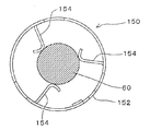
実施例2の防振部材は、図9に示すように、1つの円環状のリング部152と、該リング部152の一側に配置させた板体状の3枚の防振バネ154とから構成されるリング部材150から構成されている。
また、リング部材150は、実施例1と同様に、リング部152を形成する板体の端部に交差部を形成するもので、この交差部として、リング部152の両端部から、幅の狭い舌片152a,152bをリング部152と同一曲率で延設する。
なお、防振バネ154の形状・素材及び数は、実施例1の場合と同様である。
Next, Example 2 will be described with reference to FIGS.
9 is a perspective view of the vibration isolating member of the second embodiment, FIG. 10 is a perspective view showing a state in which the vibration isolating member of FIG. 9 is attached to the guide member, and FIG. It is a top view which shows the state which mounted | wore.
As shown in FIG. 11, the anti-vibration member (ring member 150) shown in FIGS. 9 and 10 as an anti-vibration member is applied to support the operating
As shown in FIG. 9, the vibration isolating member of the second embodiment includes one
Similarly to the first embodiment, the
The shape, material, and number of the anti-vibration springs 154 are the same as those in the first embodiment.
かかる構成のリング部材150によれば、リング部材150がガイド部材100に装着された状態において、作動棒60は、図11に示すように、その周囲を3個所にて防振バネ154により支持され、リング部152は弁体30の防振部材として作用することとなる。
したがって、冷凍サイクル内に冷媒圧力の圧力変動が生じても、弁体30の動作を安定させることができ、冷媒流量の正確な制御と作動棒60の振動により生じる騒音の発生を防止することができる。
According to the
Therefore, even if refrigerant pressure fluctuations occur in the refrigeration cycle, the operation of the
なお、上記実施例において、防振バネ154は、全幅において、同一幅に形成したが、その他の形状でも良く、例えば、先端部が頂点となる三角形状とすることで、弾性度を調整するようにしても良いのは勿論である。 In the above-described embodiment, the anti-vibration springs 154 are formed to have the same width in the entire width, but other shapes may be used. For example, the elasticity may be adjusted by making the tip end a triangular shape. Of course, it is okay.
次に、実施例3について図12乃至図15を用いて説明する。
図12は、実施例3の防振部材の斜視図、図13は、図11の防振部材のガイド部材に装着した状態の斜視図、図14は、図12の防振部材の部分説明図(A)及び要部側面図(B)、図15は、図12の防振部材に作動棒を装着した状態を示す平面図である。
この実施例3は、図12乃至図14に示す防振部材(リング部材250)を、実施例1,2と同様に作動棒60の支持のために適用するものである。
そして、この作動棒60は、実施例1,2と同様に、図1に示すように、パワーエレメント70に駆動される。
Next, Embodiment 3 will be described with reference to FIGS.
12 is a perspective view of the vibration isolating member of the third embodiment, FIG. 13 is a perspective view of the vibration isolating member attached to the guide member of the vibration isolating member of FIG. 11, and FIG. 14 is a partial explanatory view of the vibration isolating member of FIG. FIG. 15A is a plan view showing a state in which an operating rod is attached to the vibration isolating member of FIG.
In the third embodiment, the vibration isolating member (ring member 250) shown in FIGS. 12 to 14 is applied to support the operating
The operating
また、リング部材250は、実施例1,2と同様に、図15に示すガイド部材100に形成された径大部120内に嵌合される。
この径大部120の内壁にリング部材250のリング部252が弾接・装着される。
実施例3のリング部材250は、図12乃至図15に示すように、リング部252の内面に形成された平板状の3枚の防振バネ254の先端部に半球状の球面部256が形成され、該球面部256が作動棒60の側面に点接触して当接・支持することになる。
また、図12乃至図14に示すように、前記リング部252には、その長さ方向に沿って切欠き部56が形成される。
なお、リング部252の両端部252a,252bは互いに重合する構造に作られており、リング部252の直径を縮めた状態で、ガイド部材100の径大部120の内径部に挿入し直径が復元する弾性力を利用して、防振部材250をガイド部材100の内側に位置決めすることができる。
Further, the
The
As shown in FIGS. 12 to 15, in the
As shown in FIGS. 12 to 14, the
In addition, both ends 252a and 252b of the
したがって、実施例3によれば、作動棒60はその周囲を3個所にて、3枚の防振バネ254の先端部に形成されている半球状の球面部256が作動棒60の側面に点接触して当接・支持されるから、リング部材250は作動棒60の防振部材として作用することとなり、冷凍サイクル内に冷媒圧力の変動が生じても、弁体30の動作を安定にすることができ、冷媒流量の正確な制御と弁体30の振動により生じる騒音の発生を防止することができる。
Therefore, according to the third embodiment, the hemispherical
また、実施例3によれば、実施例1,2と同様にリング部材250を冷媒の流路から離れた作動棒60の部分に配置させたことから、リング部材250が冷媒の流動抵抗とならず、また、リング部材250自体が冷媒の流れによる振動や騒音を発生するおそれがない。
また、図15に示すように、リング部材250の防振バネ254は作動棒60に対して点接触しているから、作動棒60が仮に多少傾斜することがあっても、円滑な支持状態が保持される。
Further, according to the third embodiment, since the
Further, as shown in FIG. 15, since the
次に、実施例4について図16及び図17を用いて説明する。
図16は、実施例4のリング部材の部分説明図(A)及び要部側面図(B)、図17は、図16のリング部材に作動棒を装着した状態を示す平面図である。
なお、図16(B)は、図16(A)の矢印方向から観た図である。
Next, Example 4 will be described with reference to FIGS. 16 and 17.
FIG. 16 is a partial explanatory view (A) and a main part side view (B) of the ring member of the fourth embodiment, and FIG. 17 is a plan view showing a state in which an operating rod is mounted on the ring member of FIG.
Note that FIG. 16B is a diagram viewed from the direction of the arrow in FIG.
実施例4は、実施例3の変形であり、図16及び図17に示す防振部材(リング部材350)を、実施例1乃至実施例3と同様に、図15に示すガイド部材100に形成された径大部120内に嵌合される。
リング部材350は、リング部352と一体の3枚の防振バネ354がその内側に形成され、その先端部が同一方向にくの字形に折り曲げられると共に、その先端部には円筒周面形状の曲面突条部356が形成され、該曲面突条部356が作動棒60の周面に点接触して支持することになる。
The fourth embodiment is a modification of the third embodiment, and the vibration isolation member (ring member 350) illustrated in FIGS. 16 and 17 is formed on the
In the
上記構成により、リング部材350は作動棒60を介して弁体30の防振部材として作用することとなり、冷凍サイクル内に冷媒圧力の変動が生じても、弁体30の動作を安定にすることができ、冷媒流量の正確な制御と弁体30の振動により生じる騒音の発生を防止することができる。
With the above configuration, the
また、実施例4によれば、他の実施例と同様に、リング部材350を冷媒の流路から離れた作動棒60の部分に配置させたことから、リング部材350が冷媒の流動抵抗とならず、また、リング部材350自体が冷媒の流れにより振動や騒音を発生するおそれがない。
また、リング部材350の防振バネ354は作動棒60に対して点接触しているから、作動棒60が仮に多少傾斜することがあっても、或いは、防振バネ354が弾性変形することがあっても円滑に支持状態が保持される。
Further, according to the fourth embodiment, as in the other embodiments, the
Further, since the
次に、実施例5について図18及び図19を用いて説明する。
図18は、実施例5のリング部材の部分説明図(A)及び要部側面図(B)、図19は、図18のリング部材に作動棒を装着した状態を示す平面図である。
なお、図18(B)は、図18(A)の矢印方向から観た図である。
実施例5は、実施例4の変形であり、防振部材(リング部材450)を、実施例4と同様に作動棒60の支持のために適用するものである。
Next, Example 5 will be described with reference to FIGS.
FIG. 18 is a partial explanatory view (A) and a main part side view (B) of the ring member of the fifth embodiment, and FIG. 19 is a plan view showing a state in which an operating rod is mounted on the ring member of FIG.
Note that FIG. 18B is a diagram viewed from the direction of the arrow in FIG.
The fifth embodiment is a modification of the fourth embodiment, in which a vibration isolating member (ring member 450) is applied to support the operating
リング部材450は、他の実施例と同様に、ガイド部材100の径大部120内に嵌合・装着される。
そして、リング部材450は、図18(A),(B)及び図19に示すように、リング部材452と一体の3枚の防振バネ454がその内側に形成され、その先端部が同一方向に折り曲げられると共に、その先端部には突条部456が形成され、該突条部456が作動棒60の周面に点接触して支持することになる。
The
As shown in FIGS. 18A, 18B, and 19, the
上記構成により、リング部材450は作動棒60を介して弁体30の防振部材として作用することとなり、冷凍サイクル内に冷媒圧力の変動が生じても、弁体30の動作を安定にすることができ、冷媒流量の正確な制御と弁体30の振動により生じる騒音の発生を防止することができる。
また、実施例5によれば、他の実施例と同様の効果が期待できる。
With the above configuration, the
Moreover, according to Example 5, the same effect as another Example can be anticipated.
ところで、図1に示す実施例1を採用した場合、弁本体10に形成された径大の段付穴14と蒸発器等への取付穴10a,10b(図21参照)とが近接して配置されることから、両穴間の肉厚が確保できないという不具合が生ずることがある。
そこで、このような問題の解決手段として発明された技術が実施例6である。
以下、実施例6について図20及び図21を用いて説明する。
By the way, when Example 1 shown in FIG. 1 is adopted, the large-diameter stepped
Thus, the sixth embodiment is a technique invented as a solution to such a problem.
Hereinafter, Example 6 will be described with reference to FIGS.
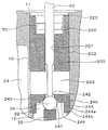
図20は、本発明の実施例6の膨張弁の断面図(図21のX−X断面)、図21は、図20の右側面図である。
なお、図20及び図21において、実施例1と同一構成部分については、図1−4と同一符号を付すことによって、その説明を省略する。
実施例6は、リング状防振バネ50の取付位置を図20に示すように、第3の通路26内に配置した点に特徴を有するものである。
20 is a cross-sectional view of the expansion valve according to the sixth embodiment of the present invention (XX cross-section of FIG. 21), and FIG. 21 is a right side view of FIG.
In FIG. 20 and FIG. 21, the same components as those in the first embodiment are denoted by the same reference numerals as those in FIG.
The sixth embodiment is characterized in that the attachment position of the ring-shaped vibration-
即ち、実施例6の場合、図20,21に示すように、弁本体10には、ガイド部材500を嵌入させる径小孔部16及び径大孔部17(実施例1の段付穴14に相当)が形成され、且つ、実施例1(特に図4参照)と比べて径小孔部16の上下の長さ(高さ)が大で、径大孔部17の上下の長さ(高さ)が小として形成される。
そして、ガイド部材500は、その下部を構成する均一径部分を実施例1と比べて長く形成し、もって、前記ガイド部材500を径小孔部16及び径大孔部17に嵌合した時に、拡大径部521の大部分が第3の通路26内に位置するように形成する。
そして、この拡大径部521内に他の実施例同様に、防振部材50を配置する。
この構成により、径大孔部17は、取付穴10a及び取付穴10bから離れた位置に設けることができるから、防振部材50の機能を保持させたままで、弁本体10における径大孔部17と取付穴10a及び取付穴10bとの間隔(肉厚)を確保することができる。
したがって、実施例6においても、実施例1と同様の防振効果を実現すると共に、弁本体10の腐食を発生させず、冷媒の漏れの惧れをなくすことができる。
That is, in the case of the sixth embodiment, as shown in FIGS. 20 and 21, the
And the
And the
With this configuration, the large-
Therefore, in the sixth embodiment, the same vibration isolation effect as that of the first embodiment can be realized, the
また、図20に示すように、ガイド部材500の下部のオリフィス部540の外周に環状のシール溝541を形成し、このシール溝541にリングシール550を嵌合させることで、弁室22と第2の通路24との間のシール性を向上させることができる。
In addition, as shown in FIG. 20, an
次に、実施例7について図22及び図23を用いて説明する。
図22は、本発明の実施例7の膨張弁の断面図、図23は、図22の右側面図である。
全体を符号1で示す膨張弁は、アルミ合金等でつくられる角柱形状の弁本体10を有し、取付用の貫通穴28が設けてある弁本体10には、高圧の冷媒が流入する第1の通路20が設けられる。
第1の通路20は、有底の弁室22に連通し、弁室22の開口部にオリフィス部材640が圧入固着される。
弁室22内には、球状の弁体30が支持部材32に溶接により取り付けられて配置され、支持部材32は、スプリング34により弁体30を常時オリフィス部材640に向けて付勢する。
Next, Example 7 will be described with reference to FIGS.
22 is a cross-sectional view of an expansion valve according to a seventh embodiment of the present invention, and FIG. 23 is a right side view of FIG.
The expansion valve denoted as a whole by
The
A
オリフィス部材640は、中央部に開口部642を有し、弁体30との間で冷媒の流路を形成する。
オリフィス部材640の内径部には防振部材650が嵌装されて弁体30の振動を防止する。
オリフィス部材640を通過した冷媒は、第2の通路24から蒸発器側へ送り出される。
蒸発器から戻る冷媒は、第3の通路26を通って圧縮機側へ送られる。
The
A
The refrigerant that has passed through the
The refrigerant returning from the evaporator is sent to the compressor side through the
弁本体10の弁室22の反対側の端部には、パワーエレメントと称する弁体30の駆動装置70が取り付けられる。
パワーエレメント70は、上蓋72aと下蓋72bが一体に溶接されたキャン体72を有し、上蓋72aと下蓋72bの間には、ダイアフラム80が挟み込まれる。
キャン体72は、ねじ部74で弁本体10に固着され、シール部材であるOリング677でシールされる。
ダイアフラム80と上蓋72aとの間には、圧力室82が形成され、作動流体が充填されて、栓体84により封止される。
A
The
The
A
ダイアフラム80の圧力室82の反対側には、ストッパ部材90が配接される。
第3の通路26の冷媒は、開口部12を介してストッパ部材90の裏面に導入される。
ストッパ部材90は、ダイアフラム80の変位に追従して摺動する。
ストッパ部材90は、作動棒60を保持し、作動棒60の先端は弁体30に当接する。
ダイアフラム80の変位は、作動棒60を介して弁体30を駆動し、オリフィス部材640との間の流路面積を制御する。
A
The refrigerant in the
The
The
The displacement of the
弁本体10に圧入されるガイド部材600は、段付部610を有し、弁本体10に対して正確に位置決めされて固着される。
ガイド部材600の内径部には、リング状のシール部材620が挿入され、プッシュナット等の止め具630により固定される。
シール部材620は、第2の通路24と第3の通路26との間の冷媒の通過をシールする。
The
A ring-shaped
The
弁本体10には、第3の通路26に連通するパワーエレメント70を取り付けるための開口した駆動装置取付穴627が形成され、弁本体10の駆動装置取付穴627の内周には環状凹溝628とめねじ部629が形成されている。
The
パワーエレメント70のキャン体72の下蓋72bには、弁本体10の駆動装置取付穴627に嵌合する円筒状の取付座673が一体に形成され、パワーエレメント70のキャン体72の取付座673の先端部の外周には弁本体10の駆動装置取付穴627のめねじ部629に螺合するおねじ部674が形成され、パワーエレメント70のキャン体72の取付座673のおねじ部674は弁本体10の駆動装置取付穴627のめねじ部629に螺合され、パワーエレメント70が弁本体10の駆動装置取付穴627に螺着されている。
A cylindrical mounting
弁本体10の駆動装置取付穴627の環状凹溝628には、パワーエレメント70のキャン体72の取付座673の外周面に密接するシール部材としてOリング677が配置されている。
An O-
パワーエレメント70のキャン体72内には、蒸発器から送出される冷媒の温度を感知して変位するダイアフラム80とダイアフラム80の変位を作動棒60に伝達するストッパ部材90が装備され、ストッパ部材90にはダイアフラム80と反対側の下面中央に円筒状の中空突起691が一体に形成され、ストッパ部材90の中空突起691には作動棒60の基端部が嵌入され、作動棒60の先端が弁体30に当接されている。
A can
次に、この膨張弁の組立手順を説明する。
まず、弁本体10のパワーエレメント70を取り付ける側の開口部12を介して弁室22にスプリング34と弁体30が溶接された支持部材32を挿入する。
Next, the procedure for assembling the expansion valve will be described.
First, the
次に、防振部材650を取り付けたオリフィス部材640の組立体を開口部12から挿入し、弁室22の開口部616に圧入する。
この圧入は、適宜の圧入工具を使用し、必要に応じて、カシメ加工を施して固着する。
Next, the assembly of the
For this press-fitting, an appropriate press-fitting tool is used, and if necessary, caulking is applied and fixed.
次に、作動棒60が挿入されたガイド部材600を開口部12から挿入し、弁本体10の段付穴614に圧入する。
ガイド部材600は、段付部610により軸方向に位置決めされる。
必要に応じて、カシメ加工を施して固着する。
Next, the
The
If necessary, apply caulking to secure.
最後に、弁本体10の駆動装置取付穴627の環状凹溝628にOリング677を嵌め込み、パワーエレメント70のキャン体72の取付座673を弁本体10の駆動装置取付穴627に嵌入し、パワーエレメント70のキャン体72の取付座673のおねじ部674を弁本体10の駆動装置取付穴627のめねじ部629に螺合させて締め付けることにより、パワーエレメント70の組立体をねじ部74により弁本体10に螺合して、膨張弁1の組立を完了する。
Finally, an O-
上記構成により、パワーエレメント70のキャン体72の取付座673のおねじ部674を弁本体10の駆動装置取付穴627のめねじ部629に螺合させて締め付けることにより、パワーエレメント70が弁本体10の駆動装置取付穴627に取り付けられ、Oリング677がパワーエレメント70のキャン体72の取付座673の外周に密接し、弁本体10の駆動装置取付穴627の内周とパワーエレメント70のキャン体72の取付座673の外周との間からの冷媒の漏れをOリング677により確実に防止することができる。
With the above configuration, the
また、パワーエレメント70のキャン体72の取付座673のおねじ部674を弁本体10の駆動装置取付穴627のめねじ部629に対して締め付ける方向または緩める方向に回転させることで、パワーエレメント70が弁本体10の駆動装置取付穴627に対して上下方向に移動し、作動棒60をパワーエレメント70と共に上下方向に移動させることができ、パワーエレメント70のキャン体72の取付座673のおねじ部674の弁本体10の駆動装置取付穴627のめねじ部629へのねじ込み量で、膨張弁1の弁体30が開き始めるセット値の微調整を行うことができる。
Further, by rotating the
1 膨張弁
10 弁本体
10a,10b,10c 取付穴
11 カシメ部
12 開口部
13 段部
14 段付穴
15 段部
16 径小孔部
17 径大孔部
20 第1の通路
22 弁室
22a 有底
24 第2の通路
26 第3の通路
28 貫通穴
30 弁体
32 支持部材
34 スプリング
40,40’ オリフィス部
40” オリフィス部材
42 絞り部
43 通路
44 案内部
44’ 壁部
45 円板部
46 平坦部
47 傾斜部
50 防振部材
52 リング部
52a,52b 両端部
54 防振バネ
56 切欠き部
60 作動棒
70 パワーエレメント(駆動装置)
72 キャン体
72a 上蓋
72b 下蓋
74 ねじ部
76 シール部材
80 ダイアフラム
82 圧力室
84 栓体
90 ストッパ部材
100 ガイド部材
101 作動棒孔
102 ガイド部
110 段部
120 径大孔部
121 径大部
122 端部
150 防振部材(リング部材 実施例2)
152 リング部
152a,152b 両端部の舌片
154 防振バネ
200 ガイド部材
201 作動棒孔
202 ガイド部
220 径大孔部
222 端部
240 オリフィス部
242 絞り部
243 通路
244 壁部
244b 端部(位置決め部)
245 円盤部
246 平坦部
247 傾斜部
250 防振部材(リング部材 実施例3)
252 リング部
252a,252b 両端部
254 防振バネ
256 球面部
350 防振部材(リング部材 実施例4)
352 リング部
354 防振バネ
356 曲面突条部
450 防振部材(リング部材 実施例5)
452 リング部
454 防振バネ
456 突条部
500 ガイド部材
521 径大部
540 オリフィス部
541 シール溝
550 リングシール
600 ガイド部材
610 段付部
614 段付穴
616 開口部
620 シール部材
627 駆動装置取付穴
628 環状凹溝
629 めねじ部
630 止め具
640 オリフィス部材
642 開口部
650 防振部材
673 取付座
674 おねじ部
677 Oリング(シール部材)
691 中空突起
DESCRIPTION OF
72 Can
152
245
252
352
452
691 Hollow protrusion
Claims (16)
Priority Applications (5)
| Application Number | Priority Date | Filing Date | Title |
|---|---|---|---|
| JP2004207257A JP4255892B2 (en) | 2003-11-06 | 2004-07-14 | Expansion valve |
| DE602005001293T DE602005001293T2 (en) | 2004-05-17 | 2005-04-27 | expansion valve |
| EP05009181A EP1598581B1 (en) | 2004-05-17 | 2005-04-27 | Expansion valve |
| US11/127,218 US7373788B2 (en) | 2004-05-17 | 2005-05-12 | Expansion valve |
| KR1020050040545A KR101141237B1 (en) | 2004-05-17 | 2005-05-16 | Expansion valve |
Applications Claiming Priority (3)
| Application Number | Priority Date | Filing Date | Title |
|---|---|---|---|
| JP2003377476 | 2003-11-06 | ||
| JP2004146294 | 2004-05-17 | ||
| JP2004207257A JP4255892B2 (en) | 2003-11-06 | 2004-07-14 | Expansion valve |
Publications (3)
| Publication Number | Publication Date |
|---|---|
| JP2006003056A JP2006003056A (en) | 2006-01-05 |
| JP2006003056A5 JP2006003056A5 (en) | 2006-11-30 |
| JP4255892B2 true JP4255892B2 (en) | 2009-04-15 |
Family
ID=35771592
Family Applications (1)
| Application Number | Title | Priority Date | Filing Date |
|---|---|---|---|
| JP2004207257A Expired - Fee Related JP4255892B2 (en) | 2003-11-06 | 2004-07-14 | Expansion valve |
Country Status (1)
| Country | Link |
|---|---|
| JP (1) | JP4255892B2 (en) |
Families Citing this family (6)
| Publication number | Priority date | Publication date | Assignee | Title |
|---|---|---|---|---|
| JP5906371B2 (en) * | 2012-01-11 | 2016-04-20 | 株式会社テージーケー | Expansion valve and anti-vibration spring |
| JP6064114B2 (en) | 2012-03-22 | 2017-01-25 | 株式会社テージーケー | Expansion valve |
| JP6143500B2 (en) * | 2013-03-08 | 2017-06-07 | 株式会社不二工機 | Thermal expansion valve |
| JP6697975B2 (en) * | 2016-08-09 | 2020-05-27 | 株式会社不二工機 | Expansion valve |
| JP6697976B2 (en) * | 2016-08-09 | 2020-05-27 | 株式会社不二工機 | Expansion valve |
| JP6943379B2 (en) * | 2016-08-09 | 2021-09-29 | 株式会社不二工機 | Expansion valve |
-
2004
- 2004-07-14 JP JP2004207257A patent/JP4255892B2/en not_active Expired - Fee Related
Also Published As
| Publication number | Publication date |
|---|---|
| JP2006003056A (en) | 2006-01-05 |
Similar Documents
| Publication | Publication Date | Title |
|---|---|---|
| US7373788B2 (en) | Expansion valve | |
| US9702601B2 (en) | Expansion valve and vibration-proof spring | |
| US9909793B2 (en) | Expansion valve and vibration-proof spring | |
| CN100404925C (en) | Expansion valve | |
| JP2005156046A (en) | Expansion valve | |
| JP4255892B2 (en) | Expansion valve | |
| US6935573B2 (en) | Expansion valve | |
| US20040020996A1 (en) | Expansion valve | |
| US7418973B2 (en) | Device to reduce noise in pressure regulators | |
| JP4136597B2 (en) | Expansion valve | |
| JP2001012824A (en) | Control valve | |
| WO2018030115A1 (en) | Expansion valve | |
| JP4335713B2 (en) | Thermal expansion valve | |
| JP6788887B2 (en) | Expansion valve | |
| JP4283180B2 (en) | Expansion valve | |
| US6776351B2 (en) | Expansion valve | |
| JP2020071006A (en) | Expansion valve | |
| JP5501104B2 (en) | Expansion valve | |
| JP4146255B2 (en) | Expansion valve | |
| JP2020176723A (en) | Expansion valve | |
| JP2001091109A (en) | Expansion valve | |
| JP2001091108A (en) | Expansion valve | |
| JP2005226941A (en) | Expansion valve | |
| JP2001133082A (en) | Expansion valve | |
| JP2004050893A (en) | Expansion valve |
Legal Events
| Date | Code | Title | Description |
|---|---|---|---|
| A521 | Request for written amendment filed |
Free format text: JAPANESE INTERMEDIATE CODE: A523 Effective date: 20061013 |
|
| A621 | Written request for application examination |
Free format text: JAPANESE INTERMEDIATE CODE: A621 Effective date: 20061013 |
|
| A131 | Notification of reasons for refusal |
Free format text: JAPANESE INTERMEDIATE CODE: A131 Effective date: 20080909 |
|
| A521 | Request for written amendment filed |
Free format text: JAPANESE INTERMEDIATE CODE: A523 Effective date: 20081106 |
|
| TRDD | Decision of grant or rejection written | ||
| A01 | Written decision to grant a patent or to grant a registration (utility model) |
Free format text: JAPANESE INTERMEDIATE CODE: A01 Effective date: 20090127 |
|
| A01 | Written decision to grant a patent or to grant a registration (utility model) |
Free format text: JAPANESE INTERMEDIATE CODE: A01 |
|
| A61 | First payment of annual fees (during grant procedure) |
Free format text: JAPANESE INTERMEDIATE CODE: A61 Effective date: 20090128 |
|
| FPAY | Renewal fee payment (event date is renewal date of database) |
Free format text: PAYMENT UNTIL: 20120206 Year of fee payment: 3 |
|
| R150 | Certificate of patent or registration of utility model |
Ref document number: 4255892 Country of ref document: JP Free format text: JAPANESE INTERMEDIATE CODE: R150 Free format text: JAPANESE INTERMEDIATE CODE: R150 |
|
| FPAY | Renewal fee payment (event date is renewal date of database) |
Free format text: PAYMENT UNTIL: 20120206 Year of fee payment: 3 |
|
| FPAY | Renewal fee payment (event date is renewal date of database) |
Free format text: PAYMENT UNTIL: 20130206 Year of fee payment: 4 |
|
| R250 | Receipt of annual fees |
Free format text: JAPANESE INTERMEDIATE CODE: R250 |
|
| FPAY | Renewal fee payment (event date is renewal date of database) |
Free format text: PAYMENT UNTIL: 20140206 Year of fee payment: 5 |
|
| R250 | Receipt of annual fees |
Free format text: JAPANESE INTERMEDIATE CODE: R250 |
|
| R250 | Receipt of annual fees |
Free format text: JAPANESE INTERMEDIATE CODE: R250 |
|
| R250 | Receipt of annual fees |
Free format text: JAPANESE INTERMEDIATE CODE: R250 |
|
| R250 | Receipt of annual fees |
Free format text: JAPANESE INTERMEDIATE CODE: R250 |
|
| R250 | Receipt of annual fees |
Free format text: JAPANESE INTERMEDIATE CODE: R250 |
|
| R250 | Receipt of annual fees |
Free format text: JAPANESE INTERMEDIATE CODE: R250 |
|
| R250 | Receipt of annual fees |
Free format text: JAPANESE INTERMEDIATE CODE: R250 |
|
| LAPS | Cancellation because of no payment of annual fees |