JP5424397B2 - Control valve and swash plate type variable capacity compressor with control valve - Google Patents
Control valve and swash plate type variable capacity compressor with control valve Download PDFInfo
- Publication number
- JP5424397B2 JP5424397B2 JP2009277057A JP2009277057A JP5424397B2 JP 5424397 B2 JP5424397 B2 JP 5424397B2 JP 2009277057 A JP2009277057 A JP 2009277057A JP 2009277057 A JP2009277057 A JP 2009277057A JP 5424397 B2 JP5424397 B2 JP 5424397B2
- Authority
- JP
- Japan
- Prior art keywords
- pressure
- control valve
- chamber
- bellows
- suction chamber
- Prior art date
- Legal status (The legal status is an assumption and is not a legal conclusion. Google has not performed a legal analysis and makes no representation as to the accuracy of the status listed.)
- Expired - Fee Related
Links
Images


Classifications
-
- F—MECHANICAL ENGINEERING; LIGHTING; HEATING; WEAPONS; BLASTING
- F04—POSITIVE - DISPLACEMENT MACHINES FOR LIQUIDS; PUMPS FOR LIQUIDS OR ELASTIC FLUIDS
- F04B—POSITIVE-DISPLACEMENT MACHINES FOR LIQUIDS; PUMPS
- F04B27/00—Multi-cylinder pumps specially adapted for elastic fluids and characterised by number or arrangement of cylinders
- F04B27/08—Multi-cylinder pumps specially adapted for elastic fluids and characterised by number or arrangement of cylinders having cylinders coaxial with, or parallel or inclined to, main shaft axis
- F04B27/14—Control
- F04B27/16—Control of pumps with stationary cylinders
- F04B27/18—Control of pumps with stationary cylinders by varying the relative positions of a swash plate and a cylinder block
- F04B27/1804—Controlled by crankcase pressure
-
- F—MECHANICAL ENGINEERING; LIGHTING; HEATING; WEAPONS; BLASTING
- F04—POSITIVE - DISPLACEMENT MACHINES FOR LIQUIDS; PUMPS FOR LIQUIDS OR ELASTIC FLUIDS
- F04B—POSITIVE-DISPLACEMENT MACHINES FOR LIQUIDS; PUMPS
- F04B17/00—Pumps characterised by combination with, or adaptation to, specific driving engines or motors
- F04B17/03—Pumps characterised by combination with, or adaptation to, specific driving engines or motors driven by electric motors
- F04B17/04—Pumps characterised by combination with, or adaptation to, specific driving engines or motors driven by electric motors using solenoids
-
- F—MECHANICAL ENGINEERING; LIGHTING; HEATING; WEAPONS; BLASTING
- F04—POSITIVE - DISPLACEMENT MACHINES FOR LIQUIDS; PUMPS FOR LIQUIDS OR ELASTIC FLUIDS
- F04B—POSITIVE-DISPLACEMENT MACHINES FOR LIQUIDS; PUMPS
- F04B27/00—Multi-cylinder pumps specially adapted for elastic fluids and characterised by number or arrangement of cylinders
- F04B27/08—Multi-cylinder pumps specially adapted for elastic fluids and characterised by number or arrangement of cylinders having cylinders coaxial with, or parallel or inclined to, main shaft axis
- F04B27/14—Control
- F04B27/16—Control of pumps with stationary cylinders
- F04B27/18—Control of pumps with stationary cylinders by varying the relative positions of a swash plate and a cylinder block
- F04B27/1804—Controlled by crankcase pressure
- F04B2027/1809—Controlled pressure
- F04B2027/1813—Crankcase pressure
-
- F—MECHANICAL ENGINEERING; LIGHTING; HEATING; WEAPONS; BLASTING
- F04—POSITIVE - DISPLACEMENT MACHINES FOR LIQUIDS; PUMPS FOR LIQUIDS OR ELASTIC FLUIDS
- F04B—POSITIVE-DISPLACEMENT MACHINES FOR LIQUIDS; PUMPS
- F04B27/00—Multi-cylinder pumps specially adapted for elastic fluids and characterised by number or arrangement of cylinders
- F04B27/08—Multi-cylinder pumps specially adapted for elastic fluids and characterised by number or arrangement of cylinders having cylinders coaxial with, or parallel or inclined to, main shaft axis
- F04B27/14—Control
- F04B27/16—Control of pumps with stationary cylinders
- F04B27/18—Control of pumps with stationary cylinders by varying the relative positions of a swash plate and a cylinder block
- F04B27/1804—Controlled by crankcase pressure
- F04B2027/1822—Valve-controlled fluid connection
- F04B2027/1827—Valve-controlled fluid connection between crankcase and discharge chamber
-
- F—MECHANICAL ENGINEERING; LIGHTING; HEATING; WEAPONS; BLASTING
- F04—POSITIVE - DISPLACEMENT MACHINES FOR LIQUIDS; PUMPS FOR LIQUIDS OR ELASTIC FLUIDS
- F04B—POSITIVE-DISPLACEMENT MACHINES FOR LIQUIDS; PUMPS
- F04B27/00—Multi-cylinder pumps specially adapted for elastic fluids and characterised by number or arrangement of cylinders
- F04B27/08—Multi-cylinder pumps specially adapted for elastic fluids and characterised by number or arrangement of cylinders having cylinders coaxial with, or parallel or inclined to, main shaft axis
- F04B27/14—Control
- F04B27/16—Control of pumps with stationary cylinders
- F04B27/18—Control of pumps with stationary cylinders by varying the relative positions of a swash plate and a cylinder block
- F04B27/1804—Controlled by crankcase pressure
- F04B2027/184—Valve controlling parameter
- F04B2027/185—Discharge pressure
-
- F—MECHANICAL ENGINEERING; LIGHTING; HEATING; WEAPONS; BLASTING
- F04—POSITIVE - DISPLACEMENT MACHINES FOR LIQUIDS; PUMPS FOR LIQUIDS OR ELASTIC FLUIDS
- F04B—POSITIVE-DISPLACEMENT MACHINES FOR LIQUIDS; PUMPS
- F04B27/00—Multi-cylinder pumps specially adapted for elastic fluids and characterised by number or arrangement of cylinders
- F04B27/08—Multi-cylinder pumps specially adapted for elastic fluids and characterised by number or arrangement of cylinders having cylinders coaxial with, or parallel or inclined to, main shaft axis
- F04B27/14—Control
- F04B27/16—Control of pumps with stationary cylinders
- F04B27/18—Control of pumps with stationary cylinders by varying the relative positions of a swash plate and a cylinder block
- F04B27/1804—Controlled by crankcase pressure
- F04B2027/184—Valve controlling parameter
- F04B2027/1854—External parameters
Description
本発明は、流体通路を開閉制御する制御弁に関するものである。 The present invention relates to a control valve that controls opening and closing of a fluid passage.
流体通路を開閉制御する制御弁であって、外部からの流体の圧力を受けて伸縮するベローズを有する感圧ユニットと、ベローズの伸縮に応じて流体通路を開閉する弁体と、弁体に電磁力を作用させるソレノイドユニットとを備え、ソレノイドユニット内部に感圧ユニットが配設された制御弁が特許文献1、2に開示されている。特許文献1の制御弁では、可動コア内部に感圧ユニットが配設され、特許文献2の制御弁では、固定コア内部に感圧ユニットが配設されている。ソレノイドユニット内に感圧ユニットを配設することにより制御弁が小型化される。 A control valve that controls the opening and closing of a fluid passage. The pressure sensing unit has a bellows that expands and contracts in response to external fluid pressure, a valve body that opens and closes a fluid passage according to the expansion and contraction of the bellows, and an electromagnetic Patent Documents 1 and 2 disclose a control valve that includes a solenoid unit that applies force, and in which a pressure-sensitive unit is disposed inside the solenoid unit. In the control valve of Patent Document 1, a pressure-sensitive unit is disposed inside the movable core, and in the control valve of Patent Document 2, the pressure-sensitive unit is disposed inside the fixed core. The control valve is reduced in size by disposing the pressure sensitive unit in the solenoid unit.
特許文献1、2の制御弁には、ソレノイドユニットとは別個独立の感圧ユニットをソレノイドユニットに内蔵したので、ソレノイドユニットの構造が複雑化し、制御弁の組立性が悪化するという問題があった。
本発明は上記問題に鑑みてなされたものであり、感圧ユニットがソレノイドユニット内に配設された簡素な構造の制御弁及び制御弁を備えた斜板式可変容量圧縮機を提供することを目的とする。
The control valves of Patent Documents 1 and 2 have a problem that the structure of the solenoid unit is complicated and the assembly of the control valve is deteriorated because the pressure-sensitive unit independent of the solenoid unit is built in the solenoid unit. .
The present invention has been made in view of the above problems, and an object thereof is to provide a control valve having a simple structure in which a pressure-sensitive unit is disposed in a solenoid unit, and a swash plate type variable displacement compressor including the control valve. And
上記課題を解決するために、本発明においては、流体通路を開閉制御する制御弁であって、外部から流体の圧力を受けて伸縮するベローズを有する感圧ユニットと、ベローズの伸縮に応じて流体通路を開閉する弁体と、弁体に電磁力を作用させるソレノイドユニットとを備え、感圧ユニットがソレノイドユニット内に配設され、感圧ユニットは、ベローズの一端に強磁性材料で形成された可動端部を、ベローズの他端に強磁性材料で形成された固定端部を有し、ベローズの内部において、可動端部と固定端部が所定の隙間を隔てて対峙し、可動端部と固定端部がソレノイドユニットの磁気回路を形成することを特徴とする制御弁を提供する。
感圧ユニットの内部にソレノイドユニットの磁気回路が形成されるため、感圧ユニットの構成部品がソレノイドユニットの構成部品を兼ねることができ、構造が簡素化されてコスト低減に寄与するとともに、制御弁の組立が容易となる。
In order to solve the above-described problems, in the present invention, a control valve for controlling opening and closing of a fluid passage, which has a bellows that expands and contracts by receiving the pressure of the fluid from the outside, and a fluid according to the expansion and contraction of the bellows. A valve body that opens and closes the passage; and a solenoid unit that applies electromagnetic force to the valve body. The pressure-sensitive unit is disposed in the solenoid unit, and the pressure-sensitive unit is formed of a ferromagnetic material at one end of the bellows. The movable end portion has a fixed end portion made of a ferromagnetic material at the other end of the bellows, and the movable end portion and the fixed end portion face each other with a predetermined gap inside the bellows, and the movable end portion A control valve is provided in which the fixed end forms a magnetic circuit of a solenoid unit.
Since the magnetic circuit of the solenoid unit is formed inside the pressure-sensitive unit, the components of the pressure-sensitive unit can also serve as the components of the solenoid unit, which simplifies the structure and contributes to cost reduction. Assembling becomes easy.
本発明の好ましい態様においては、ソレノイドユニットは可動コアと固定コアとを有し、感圧ユニットの可動端部が可動コアを形成し、固定端部が固定コアを形成する。
感圧ユニットの可動端部、固定端部は、それぞれソレノイドユニットの可動コア、固定コアを形成することができる。
In a preferred aspect of the present invention, the solenoid unit has a movable core and a fixed core, the movable end of the pressure-sensitive unit forms a movable core, and the fixed end forms a fixed core.
The movable end and the fixed end of the pressure-sensitive unit can form a movable core and a fixed core of the solenoid unit, respectively.
本発明の好ましい態様においては、制御弁は、可動端部を固定端部から引き離す付勢手段を備え、付勢手段は固定端部の内部に配設されている。
付勢手段を固定端部内部に配設したため、ベローズの内部空間に突出している可動端部及び固定端部の外径をベローズ内径ぎりぎりまで大きくすることができ、両端部間の磁極面積を有効に確保できる。
In a preferred aspect of the present invention, the control valve includes urging means for pulling the movable end portion away from the fixed end portion, and the urging means is disposed inside the fixed end portion.
Since the biasing means is arranged inside the fixed end, the outer diameter of the movable end and the fixed end protruding into the inner space of the bellows can be increased to the limit of the inner diameter of the bellows, and the magnetic pole area between both ends is effective. Can be secured.
本発明の好ましい態様においては、制御弁は、固定端部の内部を貫通して可動端部に当接する非磁性材料で形成された伝達ロッドを備え、付勢手段は伝達ロッドを介して可動端部を固定端部から引き離し、伝達ロッドには可動端部と固定端部の最小隙間を規制する規制部が形成されている。
付勢手段の付勢力を伝達する非磁性材料から形成された伝達ロッドに、可動端部と固定端部との間の最小隙間を規制する規制部を設けたので、あらたな規制手段を設ける必要がなく、構造が簡素化される。
In a preferred aspect of the present invention, the control valve includes a transmission rod formed of a nonmagnetic material that penetrates the inside of the fixed end portion and contacts the movable end portion, and the urging means moves through the transmission rod to the movable end. The control rod is separated from the fixed end, and the transmission rod is formed with a restricting portion for restricting the minimum gap between the movable end and the fixed end.
Since a restricting portion that restricts the minimum gap between the movable end portion and the fixed end portion is provided on the transmission rod formed of a nonmagnetic material that transmits the urging force of the urging means, it is necessary to provide a new restricting means. And the structure is simplified.
本発明の好ましい態様においては、ソレノイドユニットは中心部に感圧ユニットを収容する有底筒状のスリーブを備え、固定端部の外周面がスリーブ内周面に圧入固定され、可動端部の外周面がスリーブ内周面に摺動可能に支持される。
感圧ユニットを容易に固定支持できるとともに、可動端部の径方向の振れを抑制できる。
In a preferred aspect of the present invention, the solenoid unit includes a bottomed cylindrical sleeve that accommodates the pressure-sensitive unit at the center, the outer peripheral surface of the fixed end is press-fitted and fixed to the inner peripheral surface of the sleeve, and the outer periphery of the movable end The surface is slidably supported on the inner circumferential surface of the sleeve.
The pressure sensitive unit can be fixed and supported easily, and the movable end can be prevented from shaking in the radial direction.
本発明の好ましい態様においては、可動端部の外周面には流体通路とベローズ周囲の空間とを連通させる連通路が形成されている。
ベローズの周囲に確実に流体圧力が作用するため、流体圧力の変化に応答してベローズが確実に伸縮動作する。
In a preferred aspect of the present invention, a communication passage is formed on the outer peripheral surface of the movable end portion to communicate the fluid passage with the space around the bellows.
Since the fluid pressure surely acts around the bellows, the bellows reliably expands and contracts in response to a change in the fluid pressure.
本発明の好ましい態様においては、感圧ユニットの内部は負圧に保持されている。
感圧ユニット内部を負圧に保持しているため、可動端部と固定端部との間の隙間に流体に混入している異物が入り込むことがなく、ベローズの伸縮動作が異物により阻害されることがない。
In the preferable aspect of this invention, the inside of a pressure sensitive unit is hold | maintained at the negative pressure.
Since the inside of the pressure-sensitive unit is maintained at a negative pressure, foreign matter mixed in the fluid does not enter the gap between the movable end and the fixed end, and the expansion and contraction of the bellows is hindered by the foreign matter. There is nothing.
本発明の好ましい態様においては、ベローズがステンレス系材料で形成されている。
軟鉄、電磁ステンレス等で形成される可動端部及び固定端部との接合性を考慮すると、ベローズをステンレス系材料で形成するのが望ましい。
In a preferred embodiment of the present invention, the bellows is formed of a stainless steel material.
In consideration of the bondability between the movable end portion and the fixed end portion made of soft iron, electromagnetic stainless steel or the like, it is desirable to form the bellows with a stainless steel material.
本発明の好ましい態様においては、流体が斜板式可変容量圧縮機を流れる冷媒であり、流体通路が、吐出室とクランク室とを連通させる連通路とクランク室と吸入室とを連通させる連通路の何れか一方又は両方であり、流体の圧力が、クランク室の圧力又は吸入室の圧力である。
制御弁が開閉制御する流体通路は、吐出室とクランク室とを連通させる連通路でも良く、或いはクランク室と吸入室とを連通させる連通路でも良く、或いは前記両者でも良い。また感圧ユニットに加わる流体圧力はクランク室の圧力でも良く、或いは吸入室の圧力でも良い。
In a preferred aspect of the present invention, the fluid is a refrigerant that flows through the swash plate type variable capacity compressor, and the fluid passage is a communication passage that connects the discharge chamber and the crank chamber, and a communication passage that connects the crank chamber and the suction chamber. Either or both, the fluid pressure is the crank chamber pressure or the suction chamber pressure.
The fluid passage controlled by the control valve may be a communication passage that connects the discharge chamber and the crank chamber, or a communication passage that connects the crank chamber and the suction chamber, or both. The fluid pressure applied to the pressure-sensitive unit may be the crank chamber pressure or the suction chamber pressure.
本発明においては、上記制御弁を備える斜板式可変容量圧縮機を提供する。
斜板式可変容量圧縮機は、冷媒圧力を感知する感圧ユニットと、感圧ユニットの動作点を変更するソレノイドユニットを備えた制御弁を使用してクランク室の圧力を調整している。本発明に係る制御弁を使用することにより、斜板式可変容量圧縮機の構造が簡素化されて製造コストが低減する。
The present invention provides a swash plate type variable displacement compressor provided with the above control valve.
The swash plate type variable capacity compressor adjusts the pressure in the crank chamber by using a control valve that includes a pressure-sensitive unit that senses refrigerant pressure and a solenoid unit that changes the operating point of the pressure-sensitive unit. By using the control valve according to the present invention, the structure of the swash plate type variable displacement compressor is simplified and the manufacturing cost is reduced.
本発明の好ましい態様においては、斜板式可変容量圧縮機は、ハウジング内に区画形成された吐出室と吸入室とクランク室と複数のシリンダボアと、シリンダボアに配設されたピストンと、クランク室を横断して配設された駆動軸と、傾角可変の斜板を有し駆動軸の回転をピストンの往復運動に変換する変換機構と、吐出室をクランク室に連通させる第1連通路と、第1連通路を開閉する制御弁と、クランク室を吸入室に連通させる第2連通路と、第2連通路に配設された絞りとを備え、制御弁の開度を調整してクランク室の圧力を変化させ、ピストンのストロークを調整して吸入室からシリンダボアに吸入される冷媒量を制御する可変容量圧縮機であって、制御弁は、感圧ユニットと弁体とが連結することによって吸入室の圧力がソレノイドの電磁力で決定される所定値より高くなると、第1連通路を閉じる方向に弁体が移動し、吸入室の圧力が所定値より低下すると第1連通路を開く方向に弁体が移動して、吸入室の圧力を所定値に自律制御する弁機構を形成し、感圧ユニットと弁体との連結部は弁機構を構成し、感圧ユニットと弁体との連結部が離間することにより弁体内部を経由してクランク室を吸入室に連通させる第3連通路が形成され、感圧ユニットの可動端部には弁体と連結する連結部材が固定され、連結部材は非磁性材料で形成されている。
弁体と感圧ユニットとの連結部が弁機構を構成しているが、連結部を非磁性材料で形成したので、連結部の当接部に磁性材料の異物が付着することがなく、連結部の当接、離間が磁性材料の異物によって損なわれることがない。
In a preferred embodiment of the present invention, a swash plate type variable displacement compressor includes a discharge chamber, a suction chamber, a crank chamber, a plurality of cylinder bores, a piston disposed in the cylinder bore, a piston disposed in the cylinder bore, and a crank chamber. A drive shaft, a conversion mechanism for converting the rotation of the drive shaft into a reciprocating motion of the piston, a first communication path for communicating the discharge chamber with the crank chamber, a first A control valve that opens and closes the communication path; a second communication path that connects the crank chamber to the suction chamber; and a throttle disposed in the second communication path; The variable capacity compressor controls the amount of refrigerant sucked from the suction chamber into the cylinder bore by adjusting the stroke of the piston, and the control valve is connected to the suction chamber by connecting the pressure sensitive unit and the valve body. The pressure of Solenoi When the pressure is higher than a predetermined value determined by the electromagnetic force, the valve body moves in the direction to close the first communication path, and when the suction chamber pressure falls below the predetermined value, the valve body moves in the direction to open the first communication path. A valve mechanism that autonomously controls the pressure in the suction chamber to a predetermined value, the connecting portion between the pressure-sensitive unit and the valve body constitutes a valve mechanism, and the connecting portion between the pressure-sensitive unit and the valve body is separated Forms a third communication passage for communicating the crank chamber with the suction chamber via the inside of the valve body, and a connecting member connected to the valve body is fixed to the movable end of the pressure-sensitive unit, and the connecting member is made of a non-magnetic material. It is formed with.
The connecting part between the valve body and the pressure-sensitive unit constitutes the valve mechanism, but since the connecting part is made of a non-magnetic material, the magnetic material foreign matter does not adhere to the contact part of the connecting part. The contact and separation of the parts are not impaired by the foreign material of the magnetic material.
本発明の実施例に係る制御弁及び斜板式可変容量圧縮機を説明する。 A control valve and a swash plate type variable displacement compressor according to an embodiment of the present invention will be described.
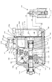
図1に示すように、斜板式可変容量圧縮機100は、複数のシリンダボア101aを備えたシリンダブロック101と、シリンダブロック101の一端に設けられたフロントハウジング102と、シリンダブロック101の他端にバルブプレート103を介して設けられたシリンダヘッド104とを備えている。
シリンダブロック101と、フロントハウジング102とによって画成されるクランク室105内を横断して、駆動軸106が設けられ、その長手方向中央部の周囲には、斜板107が配設されている。斜板107は、駆動軸106に固着されたロータ108と連結部109を介して結合し、駆動軸に対する傾角が変化可能となっている。ロータ108と斜板107との間には斜板107を最小傾角へ向けて付勢するコイルバネ110が配設され、また斜板107を挟んで反対側には斜板107を傾角が増大する方向へ向けて付勢するコイルバネ111が配設されている。
駆動軸106の一端は、フロントハウジング102の外側に突出したボス部102aを貫通してボス部の外まで延在し、図示しない動力伝達装置に連結されている。駆動軸106とボス部102aとの間には、軸封装置112が挿入され、クランク室105の内部と外部とを遮断している。駆動軸106はベアリング113、114、115、116によってラジアル方向及びスラスト方向に支持され、外部駆動源から動力が伝達された動力伝達装置に同期して回転する。
シリンダボア101a内には、ピストン117が配設され、ピストン117の一端のくぼみ117a内には、斜板107の外周縁部が収容され、シュー118を介して、ピストン117と斜板107とが互いに連動する。従って、駆動軸106の回転によりピストン117がシリンダボア101a内を往復動する。
As shown in FIG. 1, a swash plate type
A
One end of the
A
シリンダヘッド104には、吸入室119と吐出室120とが区画形成されている。吸入室119は、バルブプレート103に設けられた連通孔103aと図示しない吸入弁とを介してシリンダボア101aと連通し、吐出室120は、図示しない吐出弁とバルブプレート103に設けられた連通孔103bとを介してシリンダボア101aと連通している。
フロントハウジング102、センターガスケット(図示せず)、シリンダブロック101、シリンダガスケット(図示せず)、 吸入弁形成体(図示せず)、バルブプレート103、吐出弁形成体(図示せず)、ヘッドガスケット(図示せず)、シリンダヘッド104が、複数の通しボルト140によって締結されて圧縮機ハウジングが形成される。
A
シリンダブロック101にマフラ121が設けられている。マフラ121は蓋部材122と、シリンダブロック101外周面に形成された環状壁101bとが、図示しないシール部材を介して接合することにより形成される。マフラ空間123には逆止弁200が配設されている。逆止弁200は吐出通路124とマフラ空間123との接続部に配設され、吐出通路124(上流側)とマフラ空間123(下流側)との圧力差に応答して動作し、圧力差が所定値より小さい場合吐出通路124を遮断し、圧力差が所定値より大きい場合吐出通路124を開放する。したがって吐出室120は吐出通路124、逆止弁200、マフラ空間123及び吐出ポート122aを介してエアコンシステムの高圧側冷媒回路と接続している。
シリンダヘッド104には、エアコンシステムの低圧側冷媒回路に接続する吸入ポート104aが形成され、吸入ポート104aは吸入通路104bを介して吸入室119と接続している。
A
The
シリンダヘッド104に制御弁300が設けられている。制御弁300は吐出室120とクランク室105との間の第1連通路125の開度を調整し、クランク室105への吐出ガス導入量を制御する。クランク室105内の冷媒は、ベアリング115、116と駆動軸106との隙間を通り、室127及びバルブプレート103に設けられた固定オリフィス103cを経由する第2連通路128を通って吸入室119へ流れる。したがって制御弁300によりクランク室105への吐出ガス導入量を調整してクランク室105の圧力を変化させ、斜板107の傾角、つまりピストン117のストロークを変化させることにより吐出容量を制御することができる。制御弁300は外部信号により動作する外部制御方式の制御弁であり、連通路126を介して吸入室119の圧力を感知し、制御弁300のソレノイドユニットへの通電量を調整することにより、所定の吸入室119の圧力となるように吐出容量を制御する。
A
図2に示すように、制御弁300は、弁ユニット300Aと、ソレノイドユニット300Bとから構成される。
弁ユニット300Aは、弁ハウジング310、弁体320、弁体320を閉弁方向へ付勢するバネ330、バネの付勢力を調整する調整部材340から構成される。
弁ハウジング310内部には、弁体320の弁部320aが配設される室310aが形成され、室310aは連通孔310b及び第1連通路125の上流部分を経由して吐出室120と連通している。また室310aに隣接して室310cが形成され、室310cは弁孔310dを経由して室310aと連通し、さらに連通孔310e及び第1連通路125の下流部分を経由してクランク室105と連通している。したがって、連通孔310b、室310a、弁孔310d、室310c及び連通孔310eは第1連通路125の一部を形成している。弁孔310dの周囲には漏斗状の傾斜面から成る弁座310fが形成されている。
弁体320は弁部320a、軸部320b及び連結部320cから構成され、非磁性材料から形成されている。弁部320a、軸部320bは同一外径で円筒状に形成され、軸部320bの外周が弁ハウジング310内部に形成された挿通孔310gに摺動可能に支持され、弁部320aの端部の外周角部が弁座310fに当接、離間して弁孔310dを開閉する。連結部320cは基部が弁部320aに嵌入固定されて室310c側に延設されており、先端部320c1は後述する感圧ユニット380と接離可能に連結する。
弁体320の他端側(軸部320b)は室310hに収容され、室310hは調整部材340に形成された連通孔340a、連通路126を経由して吸入室119と連通している。弁体320の内部には連通孔320dが形成され、連通孔320dは、後述するように室310hと室310cとを連通させることが可能である。室310hと室310cとが連通孔320dを介して連通すると、第1連通路125の下流部分、連通孔310e、室310c、連通孔320d、室310h及び連通孔340a及び連通路126は、第2連通路128をバイパスしてクランク室105と吸入室119とを連通する第3連通路129を形成する。
As shown in FIG. 2, the
The
A
The
The other end side (
ソレノイドユニット300Bは、ソレノイドハウジング350、ソレノイドハウジングに収容されたモールドコイル360、ソレノイドハウジング350に固定され、モールドコイル360中心に配設された有底筒状のスリーブ370及びスリーブ370内部に収容された感圧ユニット380から構成される。
The
感圧ユニット380は、ベローズ381、ベローズの一端を閉塞する端部部材382、ベローズの他端を閉塞する端部部材383、端部部材382を端部部材383から引き離す方向へ付勢するバネ384、バネガイド385、バネ384の付勢力を端部部材382に伝達するロッド386及び端部部材382に固定された連結部387から構成される。端部部材382が感圧ユニット380の可動端部を形成し、端部部材383が固定端部を形成している。
端部部材382と端部部材383は強磁性材料で形成され、ベローズ381の内部に突出する突出部382a、383aが所定の隙間を介して対峙しているため、端部部材382はソレノイドユニット300Bの可動コア、端部部材383は固定コアとしての機能を有している。強磁性材料としては、例えば軟鉄、電磁ステンレス等が使用される。
ベローズ381の材料としては、例えば、りん青銅、ステンレス鋼等が使用される。ベローズ381と端部部材382、383は異種金属となるが、これらの接合に最適な接合方法を適用すればよい(例えば溶接、ロー付け、はんだ付け、接着等)。
軟鉄、電磁ステンレス等で形成された端部部材382及び端部部材383との接合性を考慮すると、ベローズ381をステンレス系材料で形成するのが望ましい。
ベローズ381の内部は負圧に保持されている。
The pressure-
Since the
As a material of the
In consideration of the joining property between the
The inside of the
ロッド386は、大径部386aと小径部386bとから構成され、大径部386aは端部部材382に形成された収容孔382bに収容され、小径部386bの一端はバネガイド385を介してバネ384によって付勢されている。大径部386aの端面386cは端部部材382の端面382cより僅かに突出しているため、ベローズ381が収縮すると大径部386aの端面386cが端部部材383の端面383bに当接し、端部部材382と端部部材383との間に最小隙間xminが形成される。大径部386aは端部部材382と端部部材383との間の最小隙間をxminに規制する最小隙間規制部材となっている。ロッド386は非磁性材料から形成されており、端部部材383と端部部材382とが磁化されても、ロッド386は端部部材383と端部部材382とに吸着されず、ベローズの伸縮動作を損なわない。
バネ384、バネガイド385は端部部材383の内部の室383cに収容され、室383cは蓋部材383dにより密閉されている。室383cはロッド386を挿通する挿通孔383eを経由してベローズ381内部空間388と連通し、感圧ユニット380の内部は密閉されて真空に保持されている。
突出部382a、383aの外径は、端面382cと端面383bの磁極面積を最大とすべく、ベローズ381の内部に納まる最大値に設定されている。
The
The
The outer diameters of the
スリーブ370は大径部370aと小径部370bとから構成され、開放端部は室310cに接続している。感圧ユニット380は、端部部材383の外周面383fが小径部370bの内周面に圧入固定されることにより、スリーブ370に保持されている。端部部材383の小径部370bへの圧入量は、感圧ユニット380の連結部387と弁体320の連結部320cとが当接した時に、端面382cと端面383bとの間に所定の隙間が形成されるように、より具体的には、ソレノイドユニット300Bの可動コアと固定コアとの間のギャップとベローズの伸縮量とが確保されるように、調整される。
端部部材382の外周面382dはスリーブ370の大径部370aの内周面に摺動可能に支持されている。大径部370aは強磁性体である端部部材382の外周面382dが摺動するため非磁性材料で形成し、小径部370bは端部部材383が圧入固定されるので強磁性材料で形成することが望ましい。端部部材382の外周面382dには、室310cとスリーブ370内部でベローズ周囲の空間390とを連通させる溝382eが形成されており、ベローズ381の周囲に室310c側の冷媒圧力(クランク室の圧力)が確実に作用する。溝382eは複数あっても良い。
The
The outer
ソレノイドハウジング350及びソレノイドハウジング350に接触し、モールドコイル360に埋設されたプレート361は強磁性材料で形成されており、したがってコイル362に電流が流れると、ソレノイドハウジング350、プレート361、スリーブ370の小径部370b、端部部材383、端部部材382で磁気回路が形成され、端部部材382を端部部材383に引き寄せる力が発生する。したがってソレノイドユニット300Bで発生する電磁力と冷媒圧力による力はベローズ381を収縮させる方向に作用し、バネ384の付勢力はベローズ381を伸長させる方向に作用している。従って、感圧ユニット380の可動端部(端部部材382)は、ソレノイドユニット300Bの電磁力、冷媒圧力による力及びバネの付勢力(ベローズ自身も含む)のバランスによってベローズ381の伸縮方向に変位する。
ソレノイドユニット300Bのソレノイドハウジング350端部に、弁ユニット300Aの弁ハウジング310端部が圧入固定されて制御弁300が組み立てられる。
The
The end of the
制御弁300の作動を以下に説明する。
弁体320と感圧ユニット380とが連結することによりベローズ381の伸縮動作に応じて弁体320が移動し、第1連通路125の開度が調整されて吐出室120からクランク室105に流れる冷媒ガス量が調整される。
感圧ユニット380の連結部387は、ベローズ381の伸縮に応じて弁体320の連結部320cの先端部320c1に当接、離間する。連結部387と連結部320cの先端部320c1との当接部は弁構造となっており、連結部387と連結部320cの先端部320c1が当接すると第3連通路129が遮断され、連結部387と連結部320cの先端部320c1が離間すると第3連通路129が開放される。
弁体320と感圧ユニット380とが連結している状態、つまり第1連通路125が開放されている状態では、第3連通路129は遮断され、クランク室105と吸入室119とは第2連通路128のみにより連通する。第2連通路128には固定オリフィス103cが配設されているため、弁体320の開度調整によってクランク室105の圧力が調整され、これにより斜板107の傾角が変更されて吐出容量が制御される。
The operation of the
When the
The connecting
In a state where the
ベローズ381が収縮して連結部387と連結部320cの先端部320c1とが離間している状態では、弁体320がバネ330に付勢されて弁座310fに当接し、第1連通路125が遮断されて吐出室120からクランク室105への冷媒ガスの流れが遮断される。一方クランク室105と吸入室119とは第2連通路128と第3連通路129の2つの通路により連通し、その結果クランク室105の圧力は吸入室119の圧力と同等になり、これにより斜板107の傾角が最大となって最大吐出容量が得られる。
In a state where the
弁体320には、室310h側より閉弁方向に吸入室119の圧力(Ps)が作用し、また弁孔310d側より開弁方向にクランク室105の圧力(Pc)が作用しているが、吸入室119の圧力を受ける圧力受圧面積をSr、クランク室105の圧力を受ける圧力受圧面積をSv、吐出室120の圧力をPd、バネ330の付勢力をfsとすれば、弁体320に作用する圧力及びバネ力の合力F1は
F1=fs+Ps・Sr+(Sr−Sv)・Pd−Pc・Sv (1)
となる。ここでSv=Srとなるように面積が設定されているため、
F1=fs+Ps・Sr−Pc・Sv (1´)
となる。従って、弁体320の開閉方向には吐出室120の圧力Pdは作用しない。
ソレノイドユニット300Bで発生する付勢力F2は、ソレノイドユニット300Bで発生する電磁力をf(I)、ベローズ381の有効面積をSb、ベローズの付勢力(バネ384とベローズ自身のバネ特性を合成したもの)をFbとすれば
F2=f(I)+Pc・Sb―Fb (2)
したがって制御弁の動作特性式は F1+F2=0として
fs+Ps・Sr−Pc・Sv+f(I)+Pc・Sb―Fb=0 (3)
となる。ここでSb=Svとなるように面積が設定されているため、
fs+Ps・Sr+f(I)―Fb=0
したがって
Ps=−(f(I)/Sr)+(Fb−fs)/Sr (4)
となる。
式(4)から、制御弁300は、吸入室119の圧力を感知して、電磁力によって決定される所定の吸入室119の圧力になるように弁体320を開閉制御して吐出容量を制御するものであることがわかる。尚図3に示すように、コイル362への通電量を増大すると吸入室の圧力が低下するような制御特性となっている。
Although the pressure (Ps) of the
It becomes. Here, the area is set so that Sv = Sr.
F1 = fs + Ps · Sr−Pc · Sv (1 ′)
It becomes. Accordingly, the pressure Pd of the
The urging force F2 generated by the
Therefore, the operation characteristic equation of the control valve is Fs + Ps · Sr−Pc · Sv + f (I) + Pc · Sb−Fb = 0 with F1 + F2 = 0 (3)
It becomes. Here, the area is set so that Sb = Sv.
fs + Ps · Sr + f (I) −Fb = 0
Therefore, Ps = − (f (I) / Sr) + (Fb−fs) / Sr (4)
It becomes.
From equation (4), the
制御弁300は、感圧ユニット380と弁体320とが連結することによって、吸入室119の圧力がソレノイドユニット300Bの電磁力で決定される所定値より高くなると、ベローズ381が収縮して吐出室120とクランク室105とを連通する第1連通路125を閉じる方向に弁体320が移動し、吸入室119の圧力が所定値より低下するとベローズ381が伸長して吐出室120とクランク室105とを連通する第1連通路125を開く方向に弁体320が移動して、吸入室119の圧力を所定値に自律制御する弁機構を形成している。所定の吸入室119の圧力は、調整部材340によりバネ330の付勢力fsを調整し、微調整できるようになっている。
When the
吸入室119の圧力がソレノイドユニット300Bの電磁力で決定される所定値より高い場合、ベローズ381が収縮して弁体320の弁部320aが弁座310fに当接して第1連通路125が遮断され、かつ連結部387と連結部320cとが離間して第3連通路129が開放される。これによりクランク室105と吸入室119とは第2連通路128と第3連通路129の2つの通路により連通する。
例えばエアコン起動時に、可変容量圧縮機100のクランク室105に多量の液冷媒が停留していると、従来技術では、クランク室105の液冷媒が吸入室119に抜けるまでは吐出容量がほぼ最小に維持され、しばらくの間冷房が得られないという問題を生じたが、制御弁300を使用すると、第2連通路128と第3連通路129の2つの通路によりクランク室105と吸入室119とが連通するので、クランク室105内の冷媒が速やかに吸入室119に流れ、速やかに吐出容量が増大して所定の吸入室119の圧力へ移行するという効果が得られる。ソレノイドユニット300Bの電磁力は感圧ユニット380の可動端部(端部部材382)に直接作用しているので、ソレノイドユニット300Bの電磁力で決定される所定の吸入室の圧力になるまで第3連通路129は開放される。この結果、最大吐出容量で動作している間は、第2連通路128と第3連通路129の2つの通路によりクランク室105と吸入室119とが連通し、クランク室105内の冷媒が速やかに吸入室119に流れるという効果が得られる。
連結部387と連結部320cは非磁性材料で形成されているため、端部部材382が磁化されている状態でも連結部387と連結部320cとの当接部に鉄系の異物を吸着する恐れはなく、弁構造を構成している連結部387と連結部320cとの当接部の開閉動作が損なわれることはない。
When the pressure in the
For example, when a large amount of liquid refrigerant is retained in the
Since the connecting
制御弁300においては、感圧ユニット380の内部にソレノイドユニット300Bの磁気回路が形成されるため、感圧ユニット380の構成部品382、383がソレノイドユニット300Bの構成部品、より具体的には可動コア、固定コアを兼ねることができ、構造が簡素化されてコスト低減に寄与するとともに、制御弁の組立が容易となる。
制御弁300においては、バネ384を端部部材383内部に配設したため、ベローズ381の内部空間に突出している端部部材382a、383aの外径をベローズ内径ぎりぎりまで大きくすることができ、両端部部材間の磁極面積を有効に確保できる。
制御弁300においては、バネ384の付勢力を伝達する非磁性材料から形成された伝達ロッド386に、端部部材382と端部部材383との間の最小隙間を規制する規制部を設けたので、あらたな規制手段を設ける必要がなく、構造が簡素化される。
制御弁300においては、ソレノイドユニット300Bは中心部に感圧ユニット380を収容する有底筒状のスリーブ370を備え、感圧ユニットの端部部材383の外周面がスリーブ内周面に圧入固定され、感圧ユニットの端部部材382の外周面がスリーブ内周面に摺動可能に支持されるので、感圧ユニット380を容易に固定支持できるとともに、端部部材382の径方向の振れを抑制できる。
制御弁300においては、端部部材382の外周面に室310cとベローズ周囲の空間390とを連通させる溝382eが形成されているので、ベローズの周囲に確実にクランク室圧力Pcが作用し、クランク室圧力Pcの変化に応答してベローズ381が確実に伸縮動作する。
制御弁300においては、感圧ユニット380の内部を負圧に保持しているため、端部部材382と端部部材383との間の隙間に流体に混入している異物が入り込むことがなく、ベローズ381の伸縮動作が異物により阻害されることがない。
制御弁300は、吐出室とクランク室とを連通させる連通路125のみならずクランク室と吸入室とを連通させる連通路129も開閉制御するので、クランク室と吸入室とを連通させる連通路が2系統となり、クランク室内の冷媒を迅速に吸入室へ流入させることができる。
斜板式可変容量圧縮機は、冷媒圧力を感知する感圧ユニットと、感圧ユニットの動作点を変更するソレノイドユニットを備えた制御弁を使用してクランク室の圧力を調整している。制御弁300を使用することにより、制御弁の構造が簡素化されてコスト低減を実現できる。
制御弁300においては、弁体320と感圧ユニット380との連結部387が弁機構を構成しているが、連結部387を非磁性材料で形成したので、連結部387の当接部に磁性材料の異物が付着することがなく、連結部387の当接、離間が磁性材料の異物によって損なわれることがない。
In the
In the
In the
In the
In the
In the
The
The swash plate type variable capacity compressor adjusts the pressure in the crank chamber by using a control valve that includes a pressure-sensitive unit that senses refrigerant pressure and a solenoid unit that changes the operating point of the pressure-sensitive unit. By using the
In the
図4に示すように、制御弁400は、図2の制御弁300をベースに、ソレノイドユニットの可動コアを、感圧ユニット410の可動端部を構成する第1可動コア411と、第1可動コア411に隣接配設され、開弁方向にバネ420で付勢された第2可動コア430の2つに分割したものである。
コイル362に通電されている状態では、第2可動コア430は電磁力によって第1可動コア411に吸引されて感圧ユニットの可動端部を構成し、図2の制御弁300と同じ動作を行う。制御弁400では、ソレノイドハウジング350、プレート361、スリーブ370の小径部370b、端部部材383、第1可動コア(端部部材)411、第2可動コア430で磁気回路が形成される。尚制御弁400の動作特性式は以下となる。
Ps=−(f(I)/Sr)+(Fb+fs2−fs1)/Sr (5)
fs1:バネ330の付勢力、fs2:バネ420の付勢力、
As shown in FIG. 4, the
In a state where the
Ps =-(f (I) / Sr) + (Fb + fs2-fs1) / Sr (5)
fs1: biasing force of the
コイル362を消磁した状態では、電磁力はゼロとなるため、ベローズ381が収縮して連結部387と連結部320cの先端部320c1とが離間している状態でも、バネ420の付勢力によって第2可動コア430は第1可動コア411から離間し、連結部387と連結部320cの先端部320c1とが当接して弁体320を移動させ、弁孔310dを強制開放する。これによって第1連通路125が最大開度となり、吐出室120からクランク室105に冷媒ガスが流れてクランク室105の圧力が上昇し、これにより吐出容量が最小に維持される。つまり制御弁400は、制御弁300の機能に加え、コイル362を消磁した状態で第1連通路125を最大開度とする機能を付加したものであり、いわゆるクラッチレス圧縮機に好適な制御弁となっている。
Since the electromagnetic force is zero when the
第2可動コア430には非磁性材料で形成されたロッド440が圧入固定され、ロッド440の端部は第1可動コア411に形成されたガイド孔411aに挿入されている。第2可動コア430が第1可動コア411に吸引されたとき、ロッドの端部がガイド孔411aの端部に当接し、第1可動コア411と第2可動コア430との間に微小隙間が形成されるようになっている。これによって第2可動コア430が第1可動コア411に吸着せず、コイル362を消磁したときに、バネ420の付勢力によって第2可動コア430が第1可動コア411から迅速に離間することができる。
調整部材450には図2に示すような吸入室119と連通する連通孔は形成されておらず、弁ハウジング310に吸入室119と連通する連通孔310iが形成されている。弁体320が調整部材450に当接して移動が規制されたとき、連通孔320dが室310c、室310hから遮断されるので、連通孔320dを室310cと連通させる連通孔320c2が連結部320cに形成されている。これによって弁体320の内部空間(連通孔320d)と外部空間(室310c)とが同圧となり、無用な圧力差が弁体320に作用せず、ソレノイドユニット300Bが電磁力を作用させたときに弁体320がスムーズに閉弁動作する。
A
The
上記実施例では、一方の端部部材を他方の端部部材から引き離すような付勢力を作用させるバネを他方の端部部材の内部に配設したが、バネはベローズの内部又はベローズの周囲に配設しても良い。
感圧ユニットの内部は負圧としたが、大気圧としても良い。
ベローズ内部において、端部部材と端部部材との間に非磁性材料から形成されるシムを配設し、シムの厚さを選択して最小隙間を規制しても良い。
上記実施例の制御弁は、制御弁内部にクランク室と吸入室とを連通する第3連通路を構成するものであるが、図5に示すように、第1連通路125を開閉する弁体500を備えるが、第3連通路を構成しない制御弁であっても良い。また図5に示すように感圧ユニット501に吸入室119の圧力が作用するようにしても良い。
図1〜5の実施例では、制御弁の弁体は吐出室とクランク室とを連通する連通路を開閉制御したが、図6に示すように、弁体がクランク室と吸入室とを連通する連通路を開閉制御するように制御弁を構成しても良い。この場合、図2(d)に示す感圧ユニット380の連結部387が弁体387’となり、当該弁体は非磁性材料で形成される。弁体387’が当接する弁座320c1’が端部に形成され流体通路320d’が内部に形成された筒状の弁座形成部材320c’が弁ハウジング310に固定される。図6の制御弁は構成が簡素であり、コスト低減に寄与する。
図7に示すように、吐出室とクランク室とを連通する連通路及びクランク室と吸入室とを連通する連通路にそれぞれ弁体701、702を配設し、これらの弁体を感圧ユニット703により連動制御しても良い。図7の制御弁では、弁体701が閉じる方向に動作する時に、弁体702は開く方向に動作する。図7の制御弁を使用する場合、絞り103cの開口面積を小にしても良く、或いは絞り103cを削除しても良い。
吸入室119の圧力を受ける圧力受圧面積Sr、クランク室105の圧力を受ける圧力受圧面積Sv、ベローズの有効面積Sbが異なる面積であっても良い。
流体を冷媒としたが、流体は、水、空気、オイル等その他の流体であっても良い。
In the above embodiment, the spring for applying a biasing force that separates one end member from the other end member is disposed inside the other end member. However, the spring is located inside the bellows or around the bellows. It may be arranged.
Although the inside of the pressure sensitive unit is a negative pressure, it may be an atmospheric pressure.
Within the bellows, a shim formed of a non-magnetic material may be disposed between the end member and the end member, and the thickness of the shim may be selected to restrict the minimum gap.
The control valve of the above embodiment constitutes a third communication path that communicates the crank chamber and the suction chamber inside the control valve. As shown in FIG. 5, the valve body opens and closes the
In the embodiment shown in FIGS. 1 to 5, the valve body of the control valve controls the opening and closing of the communication passage that connects the discharge chamber and the crank chamber. However, as shown in FIG. 6, the valve body communicates the crank chamber and the suction chamber. The control valve may be configured to control opening and closing of the communication path. In this case, the connecting
As shown in FIG. 7,
The pressure receiving area Sr that receives the pressure of the
Although the fluid is a refrigerant, the fluid may be other fluids such as water, air, and oil.
本発明は、流体通路を開閉制御する制御弁に広く利用可能である。 The present invention can be widely used for a control valve that controls opening and closing of a fluid passage.
100 可変容量斜板式圧縮機
101 シリンダブロック
102 フロントハウジング
103 バルブプレート
104 シリンダヘッド
125 第1連通路
128 第2連通路
129 第3連通路
300 制御弁
300A 弁ユニット
300B ソレノイドユニット
380 感圧ユニット
382、383 端部部材
100 Variable capacity
Claims (11)
Priority Applications (6)
| Application Number | Priority Date | Filing Date | Title |
|---|---|---|---|
| JP2009277057A JP5424397B2 (en) | 2009-12-04 | 2009-12-04 | Control valve and swash plate type variable capacity compressor with control valve |
| CN201080054354.4A CN102639871B (en) | 2009-12-04 | 2010-12-03 | Control valve and comprise the ramp type variable displacement compressor of control valve |
| DE112010004661.1T DE112010004661B4 (en) | 2009-12-04 | 2010-12-03 | CONTROL VALVE WITH MAGNETIC COIL AND INTEGRATED PRESSURE-SENSITIVE UNIT AND VARIABLE CAPACITY TYPE-COMPRESSOR THEREOF |
| KR1020127015249A KR20120083927A (en) | 2009-12-04 | 2010-12-03 | Control valve and variable capacity swash-plate type compressor provided with same |
| US13/513,822 US20120251343A1 (en) | 2009-12-04 | 2010-12-03 | Control Valve and Variable Capacity Swash-Plate Type Compressor Provided with same |
| PCT/JP2010/007063 WO2011067940A1 (en) | 2009-12-04 | 2010-12-03 | Control valve and variable capacity swash-plate type compressor provided with same |
Applications Claiming Priority (1)
| Application Number | Priority Date | Filing Date | Title |
|---|---|---|---|
| JP2009277057A JP5424397B2 (en) | 2009-12-04 | 2009-12-04 | Control valve and swash plate type variable capacity compressor with control valve |
Publications (2)
| Publication Number | Publication Date |
|---|---|
| JP2011117396A JP2011117396A (en) | 2011-06-16 |
| JP5424397B2 true JP5424397B2 (en) | 2014-02-26 |
Family
ID=44114802
Family Applications (1)
| Application Number | Title | Priority Date | Filing Date |
|---|---|---|---|
| JP2009277057A Expired - Fee Related JP5424397B2 (en) | 2009-12-04 | 2009-12-04 | Control valve and swash plate type variable capacity compressor with control valve |
Country Status (6)
| Country | Link |
|---|---|
| US (1) | US20120251343A1 (en) |
| JP (1) | JP5424397B2 (en) |
| KR (1) | KR20120083927A (en) |
| CN (1) | CN102639871B (en) |
| DE (1) | DE112010004661B4 (en) |
| WO (1) | WO2011067940A1 (en) |
Families Citing this family (15)
| Publication number | Priority date | Publication date | Assignee | Title |
|---|---|---|---|---|
| JP6108673B2 (en) * | 2011-12-21 | 2017-04-05 | 株式会社不二工機 | Control valve for variable displacement compressor |
| US20150068628A1 (en) * | 2012-05-24 | 2015-03-12 | Eagle Industry Co., Ltd. | Capacity control valve |
| KR101336160B1 (en) * | 2012-08-13 | 2013-12-03 | (주)신한전기 | Capacity control valve for variable displacement compressor |
| JP6005483B2 (en) * | 2012-11-08 | 2016-10-12 | サンデンホールディングス株式会社 | Variable capacity compressor |
| JP6085789B2 (en) * | 2012-12-27 | 2017-03-01 | 株式会社テージーケー | Control valve for variable capacity compressor |
| JP6115393B2 (en) * | 2013-08-08 | 2017-04-19 | 株式会社豊田自動織機 | Variable capacity swash plate compressor |
| JP2015034510A (en) * | 2013-08-08 | 2015-02-19 | 株式会社豊田自動織機 | Variable displacement swash plate compressor |
| JP6127994B2 (en) * | 2014-01-30 | 2017-05-17 | 株式会社豊田自動織機 | Variable capacity swash plate compressor |
| JP6127999B2 (en) * | 2014-02-03 | 2017-05-17 | 株式会社豊田自動織機 | Variable capacity swash plate compressor |
| JP2015183615A (en) * | 2014-03-25 | 2015-10-22 | 株式会社豊田自動織機 | Variable displacement swash plate compressor |
| JP6340501B2 (en) * | 2014-06-19 | 2018-06-13 | 株式会社テージーケー | Control valve for variable capacity compressor |
| CN105506757B (en) * | 2016-01-12 | 2018-04-17 | 东华大学 | A kind of column construction filament spinning component and spinning manifold with pressure adjusting function |
| CN105506756B (en) * | 2016-01-12 | 2018-04-17 | 东华大学 | A kind of pyramidal structure filament spinning component and spinning manifold with pressure adjusting function |
| JP6632503B2 (en) * | 2016-09-30 | 2020-01-22 | 株式会社不二工機 | Control valve for variable displacement compressor |
| JP6997536B2 (en) * | 2017-05-09 | 2022-01-17 | サンデン・オートモーティブコンポーネント株式会社 | Solenoid control valve and variable displacement compressor equipped with it |
Family Cites Families (31)
| Publication number | Priority date | Publication date | Assignee | Title |
|---|---|---|---|---|
| JPH0788138B2 (en) * | 1989-04-29 | 1995-09-27 | 日産自動車株式会社 | Vehicle air conditioner |
| JP2567947B2 (en) * | 1989-06-16 | 1996-12-25 | 株式会社豊田自動織機製作所 | Variable capacity compressor |
| JP3242496B2 (en) * | 1993-07-06 | 2001-12-25 | 株式会社豊田自動織機 | External switching type displacement control valve for variable displacement compressor |
| DE4481042C2 (en) * | 1994-07-13 | 1999-02-11 | Toyoda Automatic Loom Works | Swash plate compressor with variable displacement |
| JPH102284A (en) * | 1996-06-17 | 1998-01-06 | Toyota Autom Loom Works Ltd | Variable displacement compressor and its control method |
| JPH1054352A (en) * | 1996-08-08 | 1998-02-24 | Toyota Autom Loom Works Ltd | Variable displacement compressor |
| JPH11148576A (en) * | 1997-11-17 | 1999-06-02 | Denso Corp | Pressure control valve |
| JP4160669B2 (en) * | 1997-11-28 | 2008-10-01 | 株式会社不二工機 | Control valve for variable displacement compressor |
| JP4111593B2 (en) * | 1998-07-07 | 2008-07-02 | サンデン株式会社 | Capacity control valve mechanism of variable capacity compressor |
| JP2001020857A (en) * | 1999-07-05 | 2001-01-23 | Toyota Autom Loom Works Ltd | Control valve for variable displacement type compressor |
| JP2001140756A (en) * | 1999-11-11 | 2001-05-22 | Toyota Autom Loom Works Ltd | Control device for variable displacement type compressor |
| JP4205826B2 (en) * | 1999-11-30 | 2009-01-07 | 株式会社不二工機 | Control valve for variable displacement compressor |
| JP2001311477A (en) * | 2000-04-28 | 2001-11-09 | Nok Corp | Solenoid valve |
| JP4829419B2 (en) * | 2001-04-06 | 2011-12-07 | 株式会社不二工機 | Control valve for variable displacement compressor |
| JP4246975B2 (en) * | 2002-02-04 | 2009-04-02 | イーグル工業株式会社 | Capacity control valve |
| JP4422512B2 (en) * | 2003-04-09 | 2010-02-24 | 株式会社不二工機 | Control valve for variable capacity compressor |
| DE602004007451T2 (en) * | 2003-10-08 | 2008-03-13 | Pacific Industrial Co., Ltd., Ogaki | Pressure control valve |
| JP2005256770A (en) * | 2004-03-12 | 2005-09-22 | Tgk Co Ltd | Control valve for variable displacement compressor |
| JP4456906B2 (en) * | 2004-03-25 | 2010-04-28 | 株式会社不二工機 | Control valve for variable capacity compressor |
| JP4544927B2 (en) * | 2004-07-15 | 2010-09-15 | 株式会社鷺宮製作所 | Electric control valve and refrigeration cycle equipment |
| JP2006097673A (en) * | 2004-08-31 | 2006-04-13 | Tgk Co Ltd | Control valve for variable displacement compressor |
| JP2006170140A (en) * | 2004-12-17 | 2006-06-29 | Toyota Industries Corp | Displacement control valve for variable displacement type compressor |
| JP2006177300A (en) * | 2004-12-24 | 2006-07-06 | Toyota Industries Corp | Capacity control mechanism in variable displacement compressor |
| JP4504243B2 (en) * | 2005-04-12 | 2010-07-14 | 株式会社不二工機 | Control valve for variable displacement compressor |
| JP4572273B2 (en) * | 2005-08-17 | 2010-11-04 | 株式会社テージーケー | Control valve for variable capacity compressor |
| JP4247225B2 (en) | 2005-10-24 | 2009-04-02 | 株式会社不二工機 | Control valve for variable capacity compressor |
| JP2008038856A (en) * | 2006-08-10 | 2008-02-21 | Toyota Industries Corp | Control valve for variable displacement compressor |
| JP2008240580A (en) * | 2007-03-26 | 2008-10-09 | Tgk Co Ltd | Control valve for variable capacity compressor |
| JP2009036182A (en) * | 2007-08-03 | 2009-02-19 | Fuji Koki Corp | Control valve for variable capacity compressor |
| JP5118430B2 (en) * | 2007-09-26 | 2013-01-16 | サンデン株式会社 | Capacity control valve and variable capacity compressor using the same |
| JP4861956B2 (en) * | 2007-10-24 | 2012-01-25 | 株式会社豊田自動織機 | Capacity control valve in variable capacity compressor |
-
2009
- 2009-12-04 JP JP2009277057A patent/JP5424397B2/en not_active Expired - Fee Related
-
2010
- 2010-12-03 KR KR1020127015249A patent/KR20120083927A/en active IP Right Grant
- 2010-12-03 US US13/513,822 patent/US20120251343A1/en not_active Abandoned
- 2010-12-03 WO PCT/JP2010/007063 patent/WO2011067940A1/en active Application Filing
- 2010-12-03 CN CN201080054354.4A patent/CN102639871B/en not_active Expired - Fee Related
- 2010-12-03 DE DE112010004661.1T patent/DE112010004661B4/en not_active Expired - Fee Related
Also Published As
| Publication number | Publication date |
|---|---|
| WO2011067940A1 (en) | 2011-06-09 |
| JP2011117396A (en) | 2011-06-16 |
| US20120251343A1 (en) | 2012-10-04 |
| DE112010004661B4 (en) | 2017-02-02 |
| CN102639871B (en) | 2015-07-29 |
| CN102639871A (en) | 2012-08-15 |
| DE112010004661T5 (en) | 2012-11-08 |
| KR20120083927A (en) | 2012-07-26 |
Similar Documents
| Publication | Publication Date | Title |
|---|---|---|
| JP5424397B2 (en) | Control valve and swash plate type variable capacity compressor with control valve | |
| US6772990B2 (en) | Capacity control valve | |
| JP4303637B2 (en) | Control valve for variable capacity compressor | |
| US7726949B2 (en) | Variable displacement compressor | |
| US20050201866A1 (en) | Control valve for variable displacement compressor | |
| JP7114203B2 (en) | capacity control valve | |
| JP4714626B2 (en) | Control valve for variable displacement compressor | |
| JP7162995B2 (en) | capacity control valve | |
| JP4764721B2 (en) | Capacity control valve | |
| JP4492649B2 (en) | Bleed valve device | |
| JP7438643B2 (en) | capacity control valve | |
| JP7220963B2 (en) | capacity control valve | |
| WO2011152349A1 (en) | Pressure-sensitive control valve | |
| JP4146652B2 (en) | Capacity control valve | |
| US11473684B2 (en) | Capacity control valve | |
| WO2019139132A1 (en) | Variable capacity compressor | |
| JP5025294B2 (en) | Control valve and variable displacement compressor with control valve | |
| JP2008128091A (en) | Clutch-less variable displacement compressor | |
| WO2022131053A1 (en) | Valve | |
| US11391388B2 (en) | Capacity control valve | |
| WO2021215347A1 (en) | Capacity control valve | |
| JP2008202480A (en) | Capacity control valve for variable displacement compressor | |
| CN116368323A (en) | Valve | |
| KR20210136128A (en) | capacity control valve | |
| JP2003228424A (en) | Capacity control valve |
Legal Events
| Date | Code | Title | Description |
|---|---|---|---|
| A621 | Written request for application examination |
Free format text: JAPANESE INTERMEDIATE CODE: A621 Effective date: 20120910 |
|
| TRDD | Decision of grant or rejection written | ||
| A01 | Written decision to grant a patent or to grant a registration (utility model) |
Free format text: JAPANESE INTERMEDIATE CODE: A01 Effective date: 20131023 |
|
| A61 | First payment of annual fees (during grant procedure) |
Free format text: JAPANESE INTERMEDIATE CODE: A61 Effective date: 20131122 |
|
| R150 | Certificate of patent or registration of utility model |
Free format text: JAPANESE INTERMEDIATE CODE: R150 Ref document number: 5424397 Country of ref document: JP Free format text: JAPANESE INTERMEDIATE CODE: R150 |
|
| S533 | Written request for registration of change of name |
Free format text: JAPANESE INTERMEDIATE CODE: R313533 |
|
| R350 | Written notification of registration of transfer |
Free format text: JAPANESE INTERMEDIATE CODE: R350 |
|
| R250 | Receipt of annual fees |
Free format text: JAPANESE INTERMEDIATE CODE: R250 |
|
| R250 | Receipt of annual fees |
Free format text: JAPANESE INTERMEDIATE CODE: R250 |
|
| R250 | Receipt of annual fees |
Free format text: JAPANESE INTERMEDIATE CODE: R250 |
|
| R250 | Receipt of annual fees |
Free format text: JAPANESE INTERMEDIATE CODE: R250 |
|
| R250 | Receipt of annual fees |
Free format text: JAPANESE INTERMEDIATE CODE: R250 |
|
| LAPS | Cancellation because of no payment of annual fees |