EP1522708A2 - Zylinderblock - Google Patents
Zylinderblock Download PDFInfo
- Publication number
- EP1522708A2 EP1522708A2 EP04256187A EP04256187A EP1522708A2 EP 1522708 A2 EP1522708 A2 EP 1522708A2 EP 04256187 A EP04256187 A EP 04256187A EP 04256187 A EP04256187 A EP 04256187A EP 1522708 A2 EP1522708 A2 EP 1522708A2
- Authority
- EP
- European Patent Office
- Prior art keywords
- arch
- cylinder block
- rib
- bearing portion
- coupling surfaces
- Prior art date
- Legal status (The legal status is an assumption and is not a legal conclusion. Google has not performed a legal analysis and makes no representation as to the accuracy of the status listed.)
- Granted
Links
- 230000008878 coupling Effects 0.000 claims abstract description 19
- 238000010168 coupling process Methods 0.000 claims abstract description 19
- 238000005859 coupling reaction Methods 0.000 claims abstract description 19
- 230000005540 biological transmission Effects 0.000 claims abstract description 6
- 230000002787 reinforcement Effects 0.000 claims description 7
- 238000007789 sealing Methods 0.000 description 2
- 238000005266 casting Methods 0.000 description 1
- 238000002485 combustion reaction Methods 0.000 description 1
- 238000010276 construction Methods 0.000 description 1
- 238000010586 diagram Methods 0.000 description 1
- 239000006185 dispersion Substances 0.000 description 1
- 239000002360 explosive Substances 0.000 description 1
- 230000009347 mechanical transmission Effects 0.000 description 1
- 238000009751 slip forming Methods 0.000 description 1
Images


Classifications
-
- F—MECHANICAL ENGINEERING; LIGHTING; HEATING; WEAPONS; BLASTING
- F02—COMBUSTION ENGINES; HOT-GAS OR COMBUSTION-PRODUCT ENGINE PLANTS
- F02F—CYLINDERS, PISTONS OR CASINGS, FOR COMBUSTION ENGINES; ARRANGEMENTS OF SEALINGS IN COMBUSTION ENGINES
- F02F7/00—Casings, e.g. crankcases
- F02F7/0065—Shape of casings for other machine parts and purposes, e.g. utilisation purposes, safety
- F02F7/0068—Adaptations for other accessories
-
- F—MECHANICAL ENGINEERING; LIGHTING; HEATING; WEAPONS; BLASTING
- F02—COMBUSTION ENGINES; HOT-GAS OR COMBUSTION-PRODUCT ENGINE PLANTS
- F02F—CYLINDERS, PISTONS OR CASINGS, FOR COMBUSTION ENGINES; ARRANGEMENTS OF SEALINGS IN COMBUSTION ENGINES
- F02F7/00—Casings, e.g. crankcases
-
- F—MECHANICAL ENGINEERING; LIGHTING; HEATING; WEAPONS; BLASTING
- F02—COMBUSTION ENGINES; HOT-GAS OR COMBUSTION-PRODUCT ENGINE PLANTS
- F02F—CYLINDERS, PISTONS OR CASINGS, FOR COMBUSTION ENGINES; ARRANGEMENTS OF SEALINGS IN COMBUSTION ENGINES
- F02F7/00—Casings, e.g. crankcases
- F02F7/0002—Cylinder arrangements
- F02F7/0007—Crankcases of engines with cylinders in line
Definitions
- the present invention relates to a structure of a cylinder block and more particularly to a structure of a cylinder block rear end on which a housing, such as a transmission housing, may be mounted.
- a number of ribs are formed in vertical and radial directions in the region of a joining surface at the rear end of a cylinder block on which a transmission case is mounted.
- a cylinder block having bolt holes formed on the upper surface for connecting a cylinder head with bolts, arc-shaped coupling surfaces formed on the rear end surface for mounting housings of a transmission and the like, and a crankshaft bearing portion formed in the central part between the lower ends of the coupling surfaces
- the improvement of the structure of the cylinder block comprising: an arch-shaped rib joining the upper parts of the coupling surfaces into an arch-shape; right and left bolt hole bosses having bolt holes formed therein; the lower ends of the right and left bolt hole bosses extended and connected to the lower parts of the arch-shaped rib; and right and left main radial ribs respectively extended from the outside of the lower end of the right and left bolt hole bosses to the center of the crankshaft bearing portion.
- the upper parts of the coupling surface at the rear end of the cylinder block are joined by the arch-shaped rib into an arch-shape; the lower ends of the right and left bolt hole bosses having bolt holes formed therein extend to the lower parts of the arch-shaped rib and are joined to the arch-like rib; and the right and left main radial ribs extend from outside of the lower ends of the right and left bolt hole bosses toward the center of the crankshaft bearing portion.
- the cylinder head when the cylinder head is coupled onto the cylinder block with bolts, although a force may act to generate a falling deformation of the bolt hole boss, the cylinder block is pulled up to the side of the cylinder head and the tightening force of the bolt is dispersed excellently in the directions of the arch-shaped rib and main radial rib.
- the deformations of the cylinder and crank bearing portion are minimized, so that the roundness of the crank bearing portion is secured, thereby eliminating seizure of the crank bearing portion, sealing failure and so on.
- a top face lateral rib is formed in the lateral direction above the arch-shaped rib and right and left vertical ribs which connect both right and left ends of the top face lateral rib to the coupling surfaces and arch-shaped rib is formed outside the right and left bolt hole bosses.
- top face lateral rib is formed in the lateral direction above the arch-shaped rib and right and left vertical ribs which connect both right and left ends of the top face lateral rib to the coupling surface, and because the arch-shaped rib is formed outside the right and left bolt hole bosses, fall of the bolt hole boss due to the tightening force of the bolt can be suppressed and further, the deformation of the crank bearing portion can be suppressed excellently.
- a horizontal reinforcement rib for connecting the right and left main radial ribs is provided.
- the horizontal reinforcement rib for connecting the right and left main radial ribs is provided, stiffness of the right and left main radial ribs is enhanced by the horizontal reinforcement rib, so that the number of the ribs on the cylinder head rear end surface can be minimized, thereby securing light weight cylinder head having an excellent castability.
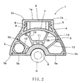
- FIG. 1 is a perspective view of the cylinder block and FIG. 2 is a side view of the rear end portion of the cylinder block.
- a cylinder head mounting face 1a on which the cylinder head is to be mounted is formed on the upper surface of the cylinder block 1.
- Four cylinder bores 2 are formed in the cylinder block 1 to extend vertically such that they are open at the upper surface of the cylinder block 1.
- a plurality of bolt holes 3 are formed at intervals in the cylinder block 1 and are positioned outside of the cylinder bores.
- Bolts are inserted from above into bolt holes 3 and are tightened, so that the cylinder head is mounted on the upper surface.
- Right/left flange-shaped reinforcement portions 1b extending outward are formed integrally with both right and left sides of the rear end of the cylinder head mounting face 1a.
- a top face lateral rib 8 which connects the right and left flange-shaped reinforcement portions 1b in a lateral direction is formed integrally with the rear end portion of the upper surface of the cylinder block 1 such that it is substantially horizontal.
- Right and left vertical ribs 9 are formed on the rear end surface so that they droop downward from both the right and left ends of the top face lateral ribs 8 and coupling surfaces 5 are formed continuously in the right and left directions such that they are curved from the lower ends of the right and left vertical ribs 9 outward in the shape of an arc.
- the upper parts of the right and left coupling surfaces 5 are joined into an arch-shape by an arch-shaped rib 7 and the lower ends of the right and left vertical ribs 9 are integrated with the right and left ends of the arch-shaped rib 7 so that they are continuously formed.
- the lower end portions of the right and left coupling surfaces 5 are formed as a horizontal bottom face rib 5a and a semi-circular crankshaft bearing portion 6 is formed integrally upward in the center of the bottom face ribs 5a.
- An oil seal O is attached to the crankshaft bearing portion 6 so that it is interleaved between the crankshaft bearing portion and an oil pan (not shown).
- a plurality of housing mounting holes 5b are formed in the coupling surfaces 5 and a mechanical transmission housing, an automatic transmission housing and the like are mounted on the coupling surface 5.
- Right and left bolt hole bosses 4 formed on the side of the rear end surface and each having the bolt hole 3 formed therein are formed inside the right and left vertical ribs 9, so that they extend from the side of the top face lateral rib 8 downward to the lower side of the arch-shaped rib 7 and the lower ends of the right and left bolt hole bosses 4 are joined to the arch-shaped rib 7.
- Right and left main radial ribs 10 are provided integrally such that they extend from outside of the lower ends of the right and left bolt hole bosses 4 toward the center of the crankshaft bearing portion 6. These right and left main radial ribs 10 are connected to each other with a horizontal reinforcement rib 11 on their lower parts so as to be reinforced.
- radial-shaped auxiliary radial ribs 12 are formed so as to connect the right and left coupling surfaces 5 with the crankshaft bearing portion 6.
- a plurality of ribs in the vertical and lateral directions are not provided on the rear end surface of the cylinder block 1 unlike the conventional cylinder block and this cylinder block is reinforced with the right and left main radial ribs 10, the auxiliary radial ribs 12, the arch-shaped rib 7, the right and left vertical ribs 9 and the top face lateral rib 8 while the number of the used ribs is smaller than the conventional case, thereby leading to reduction of weight.
- the tightening force F0 of the bolts 13 is dispersed to a force F1 in the direction of the right and left main radial ribs 10 directed to the center of the crankshaft bearing portion 6 and a force F2 in the direction of the arch of the arch-shaped rib 7, so as to suppress the deformations of the cylinder bore 2 and the crankshaft bearing portion 6 to a minimum extent.
Landscapes
- Engineering & Computer Science (AREA)
- Chemical & Material Sciences (AREA)
- Combustion & Propulsion (AREA)
- Mechanical Engineering (AREA)
- General Engineering & Computer Science (AREA)
- Cylinder Crankcases Of Internal Combustion Engines (AREA)
Applications Claiming Priority (2)
| Application Number | Priority Date | Filing Date | Title |
|---|---|---|---|
| JP2003352843 | 2003-10-10 | ||
| JP2003352843A JP4342898B2 (ja) | 2003-10-10 | 2003-10-10 | シリンダブロック構造 |
Publications (3)
| Publication Number | Publication Date |
|---|---|
| EP1522708A2 true EP1522708A2 (de) | 2005-04-13 |
| EP1522708A3 EP1522708A3 (de) | 2005-04-27 |
| EP1522708B1 EP1522708B1 (de) | 2008-01-16 |
Family
ID=34309301
Family Applications (1)
| Application Number | Title | Priority Date | Filing Date |
|---|---|---|---|
| EP04256187A Expired - Lifetime EP1522708B1 (de) | 2003-10-10 | 2004-10-06 | Zylinderblock |
Country Status (5)
| Country | Link |
|---|---|
| US (1) | US7077095B2 (de) |
| EP (1) | EP1522708B1 (de) |
| JP (1) | JP4342898B2 (de) |
| CN (1) | CN100436796C (de) |
| DE (1) | DE602004011301T2 (de) |
Cited By (1)
| Publication number | Priority date | Publication date | Assignee | Title |
|---|---|---|---|---|
| US20250059930A1 (en) * | 2022-05-06 | 2025-02-20 | Cummins Inc. | Cylinder block and internal combustion engine system |
Families Citing this family (4)
| Publication number | Priority date | Publication date | Assignee | Title |
|---|---|---|---|---|
| KR100802934B1 (ko) | 2006-08-14 | 2008-02-14 | 현대자동차주식회사 | 실린더 블록의 보강구조 |
| US9719462B2 (en) | 2015-04-29 | 2017-08-01 | GM Global Technology Operations LLC | Cylinder block for an internal combustion engine |
| JP6586986B2 (ja) * | 2017-12-19 | 2019-10-09 | マツダ株式会社 | エンジン |
| CN113090407B (zh) * | 2020-01-08 | 2023-09-05 | 卡明斯公司 | 气缸体负荷路径几何结构 |
Citations (1)
| Publication number | Priority date | Publication date | Assignee | Title |
|---|---|---|---|---|
| JPH10205389A (ja) | 1997-01-17 | 1998-08-04 | Suzuki Motor Corp | エンジンのミッションケース取付側構造 |
Family Cites Families (7)
| Publication number | Priority date | Publication date | Assignee | Title |
|---|---|---|---|---|
| JPH02102351A (ja) * | 1988-10-11 | 1990-04-13 | Honda Motor Co Ltd | エンジンのシリンダロック構造 |
| US5009205A (en) * | 1988-11-09 | 1991-04-23 | Mazda Motor Corporation | Crankshaft supporting structure for an internal combustion engine |
| JPH0417760A (ja) * | 1990-05-07 | 1992-01-22 | Mazda Motor Corp | エンジンのシリンダブロック |
| US5247915A (en) * | 1990-12-25 | 1993-09-28 | Mazda Motor Corporation | Cylinder block structure for an internal combustion engine |
| JP2000045863A (ja) * | 1998-07-31 | 2000-02-15 | Yamaha Motor Co Ltd | 多気筒内燃機関のシリンダブロック補強構造 |
| DE60125485T2 (de) | 2000-10-03 | 2007-06-28 | Mazda Motor Corp. | Motorblockstruktur für eine Brennkraftmaschine |
| DE10218354A1 (de) * | 2002-04-25 | 2003-11-06 | Daimler Chrysler Ag | Kurbelgehäuse einer Verbrennungskraftmaschine |
-
2003
- 2003-10-10 JP JP2003352843A patent/JP4342898B2/ja not_active Expired - Lifetime
-
2004
- 2004-10-06 DE DE602004011301T patent/DE602004011301T2/de not_active Expired - Lifetime
- 2004-10-06 EP EP04256187A patent/EP1522708B1/de not_active Expired - Lifetime
- 2004-10-09 CN CNB2004100835375A patent/CN100436796C/zh not_active Expired - Lifetime
- 2004-10-12 US US10/961,393 patent/US7077095B2/en not_active Expired - Lifetime
Patent Citations (1)
| Publication number | Priority date | Publication date | Assignee | Title |
|---|---|---|---|---|
| JPH10205389A (ja) | 1997-01-17 | 1998-08-04 | Suzuki Motor Corp | エンジンのミッションケース取付側構造 |
Cited By (1)
| Publication number | Priority date | Publication date | Assignee | Title |
|---|---|---|---|---|
| US20250059930A1 (en) * | 2022-05-06 | 2025-02-20 | Cummins Inc. | Cylinder block and internal combustion engine system |
Also Published As
| Publication number | Publication date |
|---|---|
| EP1522708A3 (de) | 2005-04-27 |
| JP4342898B2 (ja) | 2009-10-14 |
| US7077095B2 (en) | 2006-07-18 |
| CN1605737A (zh) | 2005-04-13 |
| EP1522708B1 (de) | 2008-01-16 |
| DE602004011301T2 (de) | 2009-01-15 |
| CN100436796C (zh) | 2008-11-26 |
| JP2005113888A (ja) | 2005-04-28 |
| DE602004011301D1 (de) | 2008-03-06 |
| US20050076876A1 (en) | 2005-04-14 |
Similar Documents
| Publication | Publication Date | Title |
|---|---|---|
| EP0038560B1 (de) | Brennkraftmaschine | |
| US4467754A (en) | Automotive internal combustion engine | |
| US5222467A (en) | Engine block | |
| US7077095B2 (en) | Cylinder block structure | |
| EP1314878A2 (de) | Zylinderblock für eine Brennkraftmaschine | |
| EP0077033B1 (de) | Lagerträgerstruktur | |
| JP5665488B2 (ja) | クロスヘッド型ディーゼル機関のクロスヘッド | |
| CN111757978B (zh) | 可变压缩比内燃机 | |
| EP0074120A2 (de) | Zylinderblock | |
| EP0056347B1 (de) | Brennkraftmaschine mit niedrigem Geräuschpegel | |
| EP0057869A2 (de) | Brennkraftmaschine mit Verbindung zum Getriebe | |
| JP7332261B2 (ja) | 多気筒内燃機関の本体ブロック | |
| JP7456713B2 (ja) | 多気筒内燃機関の本体ブロック | |
| WO2012066834A1 (ja) | クロスヘッド型ディーゼル機関のクロスヘッド | |
| JP2606040B2 (ja) | エンジンのシリンダボディ | |
| US4569317A (en) | Cylinder block of engine | |
| US20200386128A1 (en) | Structure of internal combustion engine | |
| JP2002188618A (ja) | 内燃機関用コンロッド | |
| JP4506517B2 (ja) | エンジンのv型シリンダブロック | |
| EP2290216A1 (de) | Struktur für ein kurbelgehäuse | |
| JP2002266693A (ja) | V型エンジンのシリンダブロック構造 | |
| JP2006161639A (ja) | ラダーフレーム構造 | |
| JPH02223656A (ja) | エンジンの補強部材 | |
| JP4356536B2 (ja) | エンジンのオイルパン構造 | |
| JPH0579400A (ja) | エンジンのシリンダブロツク構造 |
Legal Events
| Date | Code | Title | Description |
|---|---|---|---|
| PUAI | Public reference made under article 153(3) epc to a published international application that has entered the european phase |
Free format text: ORIGINAL CODE: 0009012 |
|
| PUAL | Search report despatched |
Free format text: ORIGINAL CODE: 0009013 |
|
| AK | Designated contracting states |
Kind code of ref document: A2 Designated state(s): AT BE BG CH CY CZ DE DK EE ES FI FR GB GR HU IE IT LI LU MC NL PL PT RO SE SI SK TR |
|
| AX | Request for extension of the european patent |
Extension state: AL HR LT LV MK |
|
| AK | Designated contracting states |
Kind code of ref document: A3 Designated state(s): AT BE BG CH CY CZ DE DK EE ES FI FR GB GR HU IE IT LI LU MC NL PL PT RO SE SI SK TR |
|
| AX | Request for extension of the european patent |
Extension state: AL HR LT LV MK |
|
| 17P | Request for examination filed |
Effective date: 20051014 |
|
| AKX | Designation fees paid |
Designated state(s): DE FR GB |
|
| GRAP | Despatch of communication of intention to grant a patent |
Free format text: ORIGINAL CODE: EPIDOSNIGR1 |
|
| GRAS | Grant fee paid |
Free format text: ORIGINAL CODE: EPIDOSNIGR3 |
|
| GRAA | (expected) grant |
Free format text: ORIGINAL CODE: 0009210 |
|
| AK | Designated contracting states |
Kind code of ref document: B1 Designated state(s): DE FR GB |
|
| REG | Reference to a national code |
Ref country code: GB Ref legal event code: FG4D |
|
| REF | Corresponds to: |
Ref document number: 602004011301 Country of ref document: DE Date of ref document: 20080306 Kind code of ref document: P |
|
| PLBE | No opposition filed within time limit |
Free format text: ORIGINAL CODE: 0009261 |
|
| STAA | Information on the status of an ep patent application or granted ep patent |
Free format text: STATUS: NO OPPOSITION FILED WITHIN TIME LIMIT |
|
| 26N | No opposition filed |
Effective date: 20081017 |
|
| REG | Reference to a national code |
Ref country code: GB Ref legal event code: 732E Free format text: REGISTERED BETWEEN 20110407 AND 20110413 |
|
| REG | Reference to a national code |
Ref country code: FR Ref legal event code: TQ |
|
| REG | Reference to a national code |
Ref country code: DE Ref legal event code: R082 Ref document number: 602004011301 Country of ref document: DE Representative=s name: RECHTS- UND PATENTANWAELTE LORENZ SEIDLER GOSS, DE |
|
| REG | Reference to a national code |
Ref country code: DE Ref legal event code: R081 Ref document number: 602004011301 Country of ref document: DE Owner name: NISSAN MOTOR CO., LTD., JP Free format text: FORMER OWNER: AICHI KIKAI KOGYO K.K., NISSAN MOTOR CO., LTD., , JP Effective date: 20111107 Ref country code: DE Ref legal event code: R082 Ref document number: 602004011301 Country of ref document: DE Representative=s name: RECHTS- UND PATENTANWAELTE LORENZ SEIDLER GOSS, DE Effective date: 20111107 Ref country code: DE Ref legal event code: R081 Ref document number: 602004011301 Country of ref document: DE Owner name: AICHI KIKAI KOGYO K.K., JP Free format text: FORMER OWNER: AICHI KIKAI KOGYO K.K., NISSAN MOTOR CO., LTD., , JP Effective date: 20111107 Ref country code: DE Ref legal event code: R081 Ref document number: 602004011301 Country of ref document: DE Owner name: NISSAN MOTOR CO., LTD., YOKOHAMA-SHI, JP Free format text: FORMER OWNER: AICHI KIKAI KOGYO K.K., NISSAN MOTOR CO., LTD., , JP Effective date: 20111107 Ref country code: DE Ref legal event code: R081 Ref document number: 602004011301 Country of ref document: DE Owner name: AICHI KIKAI KOGYO K.K., NAGOYA, JP Free format text: FORMER OWNER: AICHI KIKAI KOGYO K.K., NISSAN MOTOR CO., LTD., , JP Effective date: 20111107 Ref country code: DE Ref legal event code: R082 Ref document number: 602004011301 Country of ref document: DE Representative=s name: LORENZ SEIDLER GOSSEL RECHTSANWAELTE PATENTANW, DE Effective date: 20111107 Ref country code: DE Ref legal event code: R081 Ref document number: 602004011301 Country of ref document: DE Owner name: AICHI KIKAI KOGYO K.K., NAGOYA, JP Free format text: FORMER OWNERS: AICHI KIKAI KOGYO K.K., NAGOYA, AICHI, JP; NISSAN MOTOR CO., LTD., YOKOHAMA-SHI, KANAGAWA-KEN, JP Effective date: 20111107 Ref country code: DE Ref legal event code: R081 Ref document number: 602004011301 Country of ref document: DE Owner name: NISSAN MOTOR CO., LTD., YOKOHAMA-SHI, JP Free format text: FORMER OWNERS: AICHI KIKAI KOGYO K.K., NAGOYA, AICHI, JP; NISSAN MOTOR CO., LTD., YOKOHAMA-SHI, KANAGAWA-KEN, JP Effective date: 20111107 |
|
| REG | Reference to a national code |
Ref country code: DE Ref legal event code: R082 Ref document number: 602004011301 Country of ref document: DE Representative=s name: RECHTS- UND PATENTANWAELTE LORENZ SEIDLER GOSS, DE |
|
| REG | Reference to a national code |
Ref country code: GB Ref legal event code: 732E Free format text: REGISTERED BETWEEN 20120906 AND 20120912 |
|
| REG | Reference to a national code |
Ref country code: FR Ref legal event code: TQ Owner name: NISSAN MOTOR CO., LTD., JP Effective date: 20120905 Ref country code: FR Ref legal event code: TQ Owner name: AICHI KIKAI KOGYO KABUSHIKI KAISHA, JP Effective date: 20120905 |
|
| REG | Reference to a national code |
Ref country code: DE Ref legal event code: R081 Ref document number: 602004011301 Country of ref document: DE Owner name: NISSAN MOTOR CO., LTD., JP Free format text: FORMER OWNER: AICHI KIKAI KOGYO K.K., NISSAN MOTOR CO., LTD., RENAULT S.A.S., , FR Effective date: 20120903 Ref country code: DE Ref legal event code: R082 Ref document number: 602004011301 Country of ref document: DE Representative=s name: RECHTS- UND PATENTANWAELTE LORENZ SEIDLER GOSS, DE Effective date: 20120903 Ref country code: DE Ref legal event code: R081 Ref document number: 602004011301 Country of ref document: DE Owner name: AICHI KIKAI KOGYO K.K., JP Free format text: FORMER OWNER: AICHI KIKAI KOGYO K.K., NISSAN MOTOR CO., LTD., RENAULT S.A.S., , FR Effective date: 20120903 Ref country code: DE Ref legal event code: R081 Ref document number: 602004011301 Country of ref document: DE Owner name: AICHI KIKAI KOGYO K.K., NAGOYA, JP Free format text: FORMER OWNER: AICHI KIKAI KOGYO K.K., NISSAN MOTOR CO., LTD., RENAULT S.A.S., , FR Effective date: 20120903 Ref country code: DE Ref legal event code: R082 Ref document number: 602004011301 Country of ref document: DE Representative=s name: LORENZ SEIDLER GOSSEL RECHTSANWAELTE PATENTANW, DE Effective date: 20120903 Ref country code: DE Ref legal event code: R081 Ref document number: 602004011301 Country of ref document: DE Owner name: NISSAN MOTOR CO., LTD., YOKOHAMA-SHI, JP Free format text: FORMER OWNER: AICHI KIKAI KOGYO K.K., NISSAN MOTOR CO., LTD., RENAULT S.A.S., , FR Effective date: 20120903 Ref country code: DE Ref legal event code: R081 Ref document number: 602004011301 Country of ref document: DE Owner name: NISSAN MOTOR CO., LTD., YOKOHAMA-SHI, JP Free format text: FORMER OWNERS: AICHI KIKAI KOGYO K.K., NAGOYA, AICHI, JP; NISSAN MOTOR CO., LTD., YOKOHAMA-SHI, KANAGAWA-KEN, JP; RENAULT S.A.S., BOULOGNE-BILLANCOURT, FR Effective date: 20120903 Ref country code: DE Ref legal event code: R081 Ref document number: 602004011301 Country of ref document: DE Owner name: AICHI KIKAI KOGYO K.K., NAGOYA, JP Free format text: FORMER OWNERS: AICHI KIKAI KOGYO K.K., NAGOYA, AICHI, JP; NISSAN MOTOR CO., LTD., YOKOHAMA-SHI, KANAGAWA-KEN, JP; RENAULT S.A.S., BOULOGNE-BILLANCOURT, FR Effective date: 20120903 |
|
| REG | Reference to a national code |
Ref country code: FR Ref legal event code: PLFP Year of fee payment: 13 |
|
| REG | Reference to a national code |
Ref country code: FR Ref legal event code: PLFP Year of fee payment: 14 |
|
| REG | Reference to a national code |
Ref country code: FR Ref legal event code: PLFP Year of fee payment: 15 |
|
| REG | Reference to a national code |
Ref country code: DE Ref legal event code: R081 Ref document number: 602004011301 Country of ref document: DE Owner name: NISSAN MOTOR CO., LTD., YOKOHAMA-SHI, JP Free format text: FORMER OWNERS: AICHI KIKAI KOGYO K.K., NAGOYA, AICHI, JP; NISSAN MOTOR CO., LTD., YOKOHAMA-SHI, KANAGAWA-KEN, JP Ref country code: DE Ref legal event code: R082 Ref document number: 602004011301 Country of ref document: DE Representative=s name: GRUENECKER PATENT- UND RECHTSANWAELTE PARTG MB, DE |
|
| REG | Reference to a national code |
Ref country code: GB Ref legal event code: 732E Free format text: REGISTERED BETWEEN 20220630 AND 20220706 |
|
| PGFP | Annual fee paid to national office [announced via postgrant information from national office to epo] |
Ref country code: GB Payment date: 20230920 Year of fee payment: 20 |
|
| PGFP | Annual fee paid to national office [announced via postgrant information from national office to epo] |
Ref country code: FR Payment date: 20230920 Year of fee payment: 20 |
|
| PGFP | Annual fee paid to national office [announced via postgrant information from national office to epo] |
Ref country code: DE Payment date: 20230920 Year of fee payment: 20 |
|
| REG | Reference to a national code |
Ref country code: DE Ref legal event code: R071 Ref document number: 602004011301 Country of ref document: DE |
|
| REG | Reference to a national code |
Ref country code: GB Ref legal event code: PE20 Expiry date: 20241005 |
|
| PG25 | Lapsed in a contracting state [announced via postgrant information from national office to epo] |
Ref country code: GB Free format text: LAPSE BECAUSE OF EXPIRATION OF PROTECTION Effective date: 20241005 |
|
| PG25 | Lapsed in a contracting state [announced via postgrant information from national office to epo] |
Ref country code: GB Free format text: LAPSE BECAUSE OF EXPIRATION OF PROTECTION Effective date: 20241005 |