EP1522687A2 - Luftspaltkrümmer - Google Patents
Luftspaltkrümmer Download PDFInfo
- Publication number
- EP1522687A2 EP1522687A2 EP04018050A EP04018050A EP1522687A2 EP 1522687 A2 EP1522687 A2 EP 1522687A2 EP 04018050 A EP04018050 A EP 04018050A EP 04018050 A EP04018050 A EP 04018050A EP 1522687 A2 EP1522687 A2 EP 1522687A2
- Authority
- EP
- European Patent Office
- Prior art keywords
- shells
- inner part
- exhaust
- air
- outer part
- Prior art date
- Legal status (The legal status is an assumption and is not a legal conclusion. Google has not performed a legal analysis and makes no representation as to the accuracy of the status listed.)
- Granted
Links
Images
Classifications
-
- F—MECHANICAL ENGINEERING; LIGHTING; HEATING; WEAPONS; BLASTING
- F01—MACHINES OR ENGINES IN GENERAL; ENGINE PLANTS IN GENERAL; STEAM ENGINES
- F01N—GAS-FLOW SILENCERS OR EXHAUST APPARATUS FOR MACHINES OR ENGINES IN GENERAL; GAS-FLOW SILENCERS OR EXHAUST APPARATUS FOR INTERNAL-COMBUSTION ENGINES
- F01N13/00—Exhaust or silencing apparatus characterised by constructional features
- F01N13/08—Other arrangements or adaptations of exhaust conduits
- F01N13/10—Other arrangements or adaptations of exhaust conduits of exhaust manifolds
-
- F—MECHANICAL ENGINEERING; LIGHTING; HEATING; WEAPONS; BLASTING
- F01—MACHINES OR ENGINES IN GENERAL; ENGINE PLANTS IN GENERAL; STEAM ENGINES
- F01N—GAS-FLOW SILENCERS OR EXHAUST APPARATUS FOR MACHINES OR ENGINES IN GENERAL; GAS-FLOW SILENCERS OR EXHAUST APPARATUS FOR INTERNAL-COMBUSTION ENGINES
- F01N13/00—Exhaust or silencing apparatus characterised by constructional features
- F01N13/18—Construction facilitating manufacture, assembly, or disassembly
- F01N13/1888—Construction facilitating manufacture, assembly, or disassembly the housing of the assembly consisting of two or more parts, e.g. two half-shells
- F01N13/1894—Construction facilitating manufacture, assembly, or disassembly the housing of the assembly consisting of two or more parts, e.g. two half-shells the parts being assembled in longitudinal direction
-
- F—MECHANICAL ENGINEERING; LIGHTING; HEATING; WEAPONS; BLASTING
- F01—MACHINES OR ENGINES IN GENERAL; ENGINE PLANTS IN GENERAL; STEAM ENGINES
- F01N—GAS-FLOW SILENCERS OR EXHAUST APPARATUS FOR MACHINES OR ENGINES IN GENERAL; GAS-FLOW SILENCERS OR EXHAUST APPARATUS FOR INTERNAL-COMBUSTION ENGINES
- F01N13/00—Exhaust or silencing apparatus characterised by constructional features
- F01N13/08—Other arrangements or adaptations of exhaust conduits
- F01N13/10—Other arrangements or adaptations of exhaust conduits of exhaust manifolds
- F01N13/102—Other arrangements or adaptations of exhaust conduits of exhaust manifolds having thermal insulation
-
- F—MECHANICAL ENGINEERING; LIGHTING; HEATING; WEAPONS; BLASTING
- F01—MACHINES OR ENGINES IN GENERAL; ENGINE PLANTS IN GENERAL; STEAM ENGINES
- F01N—GAS-FLOW SILENCERS OR EXHAUST APPARATUS FOR MACHINES OR ENGINES IN GENERAL; GAS-FLOW SILENCERS OR EXHAUST APPARATUS FOR INTERNAL-COMBUSTION ENGINES
- F01N13/00—Exhaust or silencing apparatus characterised by constructional features
- F01N13/18—Construction facilitating manufacture, assembly, or disassembly
- F01N13/1872—Construction facilitating manufacture, assembly, or disassembly the assembly using stamp-formed parts or otherwise deformed sheet-metal
-
- F—MECHANICAL ENGINEERING; LIGHTING; HEATING; WEAPONS; BLASTING
- F01—MACHINES OR ENGINES IN GENERAL; ENGINE PLANTS IN GENERAL; STEAM ENGINES
- F01N—GAS-FLOW SILENCERS OR EXHAUST APPARATUS FOR MACHINES OR ENGINES IN GENERAL; GAS-FLOW SILENCERS OR EXHAUST APPARATUS FOR INTERNAL-COMBUSTION ENGINES
- F01N2450/00—Methods or apparatus for fitting, inserting or repairing different elements
- F01N2450/22—Methods or apparatus for fitting, inserting or repairing different elements by welding or brazing
-
- F—MECHANICAL ENGINEERING; LIGHTING; HEATING; WEAPONS; BLASTING
- F01—MACHINES OR ENGINES IN GENERAL; ENGINE PLANTS IN GENERAL; STEAM ENGINES
- F01N—GAS-FLOW SILENCERS OR EXHAUST APPARATUS FOR MACHINES OR ENGINES IN GENERAL; GAS-FLOW SILENCERS OR EXHAUST APPARATUS FOR INTERNAL-COMBUSTION ENGINES
- F01N2470/00—Structure or shape of exhaust gas passages, pipes or tubes
- F01N2470/24—Concentric tubes or tubes being concentric to housing, e.g. telescopically assembled
-
- F—MECHANICAL ENGINEERING; LIGHTING; HEATING; WEAPONS; BLASTING
- F01—MACHINES OR ENGINES IN GENERAL; ENGINE PLANTS IN GENERAL; STEAM ENGINES
- F01N—GAS-FLOW SILENCERS OR EXHAUST APPARATUS FOR MACHINES OR ENGINES IN GENERAL; GAS-FLOW SILENCERS OR EXHAUST APPARATUS FOR INTERNAL-COMBUSTION ENGINES
- F01N2530/00—Selection of materials for tubes, chambers or housings
- F01N2530/02—Corrosion resistive metals
- F01N2530/04—Steel alloys, e.g. stainless steel
-
- F—MECHANICAL ENGINEERING; LIGHTING; HEATING; WEAPONS; BLASTING
- F02—COMBUSTION ENGINES; HOT-GAS OR COMBUSTION-PRODUCT ENGINE PLANTS
- F02B—INTERNAL-COMBUSTION PISTON ENGINES; COMBUSTION ENGINES IN GENERAL
- F02B37/00—Engines characterised by provision of pumps driven at least for part of the time by exhaust
Definitions
- the present invention relates to an air gap manifold for connection exhaust gas outlet openings of an internal combustion engine, in particular Motor vehicle engine, with an exhaust gas inlet opening of an exhaust system, with an inner part with several with sliding fit into one another Exhaust guides, a surrounding the inner part, gas-tight trained Outer part and an existing between the inner part and outer part Air gap.
- the invention has for its object to provide an air gap of the specify the type mentioned above, on the one hand low in the production and on the other hand allows compliance with the emission regulations.
- the formation of the exhaust ducts of the inner part of shells is special inexpensive in production. For one, the shells be pulled economically. On the other hand is the connection of the shells by common edge forming, in particular folding, particularly favorable in the production. Especially against welded joints There is a big cost advantage, especially if at Exhaust manifolds for turbocharger must be manufactured without welding spatter. Only expensive laser and TIG welding techniques can then be considered.
- the forming compound of the shells according to the invention is for a sweat-spatter-free and on the other hand with little effort feasible. The tightness of the forming connection between the shells is sufficient, because the outer shell of the manifold is completely gas-tight and therefore a slight leakage of the inner part does not cause problems leads.
- the sheet thickness of the inner part can be kept relatively low because of the forming compound the shells, unlike welding, do not require a minimum thickness is. This allows different types of steel, for example also be used austenitic steel.
- the shells of the outer part are preferably welded together.
- the welded joints can be arranged on the outside, so that there is no risk of contamination of the interior of the exhaust manifold. It can also be used by cheaper welding processes become.
- the inner shells In order to prevent a displacement of the shells of the inner part in use, can the inner shells by single welding points against each other be locked. Because only single welds are needed to one To prevent displacement safely, this can be simple spot welds be used without unduly increasing costs. Alternatively or additionally, the shells can be embossed together.
- the outer part preferably consists of two half-shells.
- the exhaust ducts of the inner part preferably each consist of two half-shells.
- a particularly advantageous use of the air gap bend according to the invention is given in turbocharged internal combustion engines, as the inventive manifold particularly inexpensive sweat spatter can be made.
- the preparation of an air gap bend according to the invention takes place preferably such that first each one of the exhaust ducts forming shells of the inner part according to the desired sliding seat arrangement into each other, then each one the other Part of the exhaust ducts forming shells also, and then only the associated shells of the exhaust ducts together be joined by pairwise together edge deformed, in particular folded.
- the individual exhaust ducts are initially composed of, for example, two shells and then the thus formed exhaust ducts inserted into each other, but the nesting is done separately for each half of the inner part, and only then become the two halves of all exhaust ducts of the inner part simultaneously connected with each other.
- the cross sections of the exhaust ducts in the sliding seat areas together are adjusted.
- the shells of the inner part are preferably made of sheet metal, in particular by deep drawing. Preferably beads are embossed to to increase the rigidity of the shells.
- each exhaust system made two half-shells, which then simultaneously with the other Half shells are joined together.
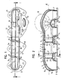
- the illustrated air-gap manifold comprises an inner part 1 with several with sliding fit into one another plugged exhaust ducts 2, 3 and 4 and a surrounding the inner part 1 with distance, gas-tight Outer part 5. Between inner part 1 and outer part 5 is characterized Air gap 6 is formed, which is a thermal insulation of the exhaust manifold causes.
- the exhaust ducts 2, 3 and 4 are each composed of two half-shells 2a and 2b, 3a and 3b, 4a and 4b, which are connected to one another at the edge are.
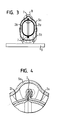
- the connection is a folded connection, as they are in Fig. 4 is shown.
- the edge of a half-shell 3a is for this bent over the edge of the other half-shell 3b. Subsequently, the Fold 7, as shown by dashed lines, tilted to the strength of the Increase connection.
- the exhaust ducts 2, 3 and 4 are, as I said, with sliding fit into each other plugged.
- the fold ends 7 at one end 2 ', 3' of the Exhaust ducts 2 and 3 before the end of the respective exhaust duct 2, 3rd As a result, a falzoker area 8 is formed, to which the associated End 3 ", 4" of the adjacent exhaust system 2, 3 and 4 with sliding seat is arranged.
- the other end 2 "of the exhaust duct 2 is together with the outer shell 5 gas-tightly connected to a first inlet flange 9.
- a second Inlet flange 10 is gas-tight with the outer shell 5 and the end 11 'of a lateral branch 11 of the exhaust system 3 is connected.
- third and fourth inlet flanges 12, 13 are finally connected to the outer shell 5 and each a rigid sleeve 14, 14 'connected gas-tight.
- the sleeve 14 is seated with sliding seat in a lateral branch 15 of the exhaust system 4 and the sleeve 14 'also with sliding fit in the second end 4' of the exhaust system 4th
- the exhaust system 4 has a second branch 16, into which a another sleeve 17 is inserted with sliding seat.
- This sleeve 17 is together connected to the outer part 5 gas-tight with an outlet flange 18.
- a secondary pipe of a conventional Exhaust system can be connected. Accordingly, the inlet flanges 9, 10, 12 and 13 at exhaust outlet openings of an internal combustion engine connected.
- the outer part 5 also has two half shells 5a, 5b.
- the dividing plane I of the half-shells 5a and 5b extends at an angle of about 90 ° to the parting plane II of the half-shells 2a, 2b, 3a, 3b, 4a and 4b of the inner part 1, and approximately parallel to the plane of the flanges 9, 10, 12th and 13.
- the production of the illustrated air-gap bend essentially takes place in such a way that first all half-shells 2a, 2b, 3a, 3b, 4a and 4b of the Inner part 1 and 5a and 5b of the outer part 5 are produced. There can be introduced into the half-shells beads 19. Then be each one half shells 2a, 3a and 4a of the inner part 1 accordingly the desired sliding seat assembly inserted into each other. Corresponding The half-shells 2b, 3b and 4b of the inner part 1 into each other plugged. After inserting the sleeves 14 and 14 'are in one another inserted half-shells 2a, 3a and 4a and 2b, 3b and 4b in a forming tool inserted.
- the inner part is finished and will after removal from the forming tool inserted into the lower shell 5b of the outer part 5. Together with this, the inner part 1 is then gas-tight with the inlet flanges 9, 10, 12 and 13 connected, in particular welded. Then the Sleeve 17 together with the upper shell 5a of the outer part 5 gas-tight with welded to the outlet flange 18. Subsequently, the upper shell 5a of the outer part 5 is placed on the lower shell 5b and in the overlapping area gas-tight welded.
- the two half-shells 5a, 5b of Outer part 5 can be joined together by normal welding methods be because the weld is on the outside.
- the illustrated and described embodiment of the inner part with sliding seats allows otherwise in a known manner a substantially unhindered thermal expansion of the exhaust gas ducts 2, 3 and 4 of the Inner part 1, in particular a larger thermal expansion due to greater heating of the inner part 1 relative to the outer part 5.
- the Outer part 5 on the other hand ensures a high gas tightness of the Lucasspaltkrümmers. In this way can with relatively very low Cost a well-fit air gap manifold can be produced.
Landscapes
- Engineering & Computer Science (AREA)
- Chemical & Material Sciences (AREA)
- Combustion & Propulsion (AREA)
- Mechanical Engineering (AREA)
- General Engineering & Computer Science (AREA)
- Exhaust Silencers (AREA)
- Medicines Containing Material From Animals Or Micro-Organisms (AREA)
- Medicines That Contain Protein Lipid Enzymes And Other Medicines (AREA)
Abstract
Description
- Fig. 1
- eine Draufsicht auf einen erfindungsgemäßen Luftspaltkrümmer mit entfernter oberer Außenschale,
- Fig. 2
- einen Schnitt durch den Luftspaltkrümmer von Fig. 1 gemäß Linie A-A,
- Fig. 3
- einen Schnitt durch den erfindungsgemäßen Luftspaltkrümmer gemäß Linie C-C in Fig. 2 und
- Fig. 4
- die Einzelheit B von Fig. 3 in vergrößerter Darstellung.
- 1
- Innenteil
- 2
- Abgasführung
- 2'
- Ende von 2
- 2"
- Ende von 2
- 2a
- Halbschale
- 2b
- Halbschale
- 3
- Abgasführung
- 3'
- Ende von 3
- 3"
- Ende von 3
- 3a
- Halbschale
- 3b
- Halbschale
- 4
- Abgasführung
- 4'
- Ende von 4
- 4"
- Ende von 4
- 4a
- Halbschale
- 4b
- Halbschale
- 5
- Außenteil
- 5a
- Halbschale
- 5b
- Halbschale
- 6
- Luftspalt
- 7
- Falz
- 8
- falzfreier Bereich
- 9
- Eingangsflansch
- 10
- Eingangsflansch
- 11
- Abzweigung von 3
- 11'
- Ende von 11
- 12
- Eingangsflansch
- 13
- Eingangsflansch
- 14, 14'
- Hülse
- 15
- Abzweigung von 4
- 16
- Abzweigung von 4
- 17
- Hülse
- 18
- Ausgangsflansch
- 19
- Sicke
- I
- Trennebene
- II
- Trennebene
Claims (10)
- Luftspaltkrümmer zur Verbindung von Abgasauslassöffnungen einer Verbrennungskraftmaschine, insbesondere Kraftfahrzeugmotor, mit einer Abgaseinlassöffnung einer Abgasanlage, mit einem Innenteil (1) mit mehreren mit Schiebesitz ineinander gesteckten Abgasführungen (2, 3, 4), einem das Innenteil (1) umgebenden, gasdicht ausgebildeten Außenteil (5) und einem zwischen Innenteil (1) und Außenteil (5) vorhandenen Luftspalt (6),
dadurch gekennzeichnet, dass
die Abgasführungen (2, 3, 4) des Innenteils (1) mindestens zum Teil durch Schalen (2a, 2b, 3a, 3b, 4a, 4b) gebildet sind, die durch gemeinsames randseitiges Umformen, insbesondere Falzen, miteinander verbunden sind. - Luftspaltkrümmer nach Anspruch 1,
dadurch gekennzeichnet, dass
das Außenteil (5) ebenfalls aus Schalen (5a, 5b) besteht. - Luftspaltkrümmer nach Anspruch 1 oder 2,
dadurch gekennzeichnet, dass
die Schalen (2a, 2b, 3a, 3b, 4a, 4b) des Innenteils (1) und/oder die Schalen (5a, 5b) des Außenteils (5) aus Blech bestehen und/oder Sicken (19) aufweisen. - Luftspaltkrümmer nach Anspruch 3,
dadurch gekennzeichnet, dass
die Schalen (5a, 5b) des Außenteils (5) miteinander verschweißt sind und/oder die Schalen (2a, 2b, 3a, 3b, 4a, 4b) des Innenteils, insbesondere durch einzelne Schweißpunkte, gegeneinander verriegelt sind. - Luftspaltkrümmer nach einem der vorhergehenden Ansprüche,
dadurch gekennzeichnet, dass
das Außenteil (5) aus zwei Halbschalen (5a, 5b) besteht. - Luftspaltkrümmer nach einem der vorhergehenden Ansprüche,
dadurch gekennzeichnet, dass
die Schalen (2a, 2b, 3a, 3b, 4a, 4b) des Innenteils (1) Halbschalen sind, wobei die Trennebene (I) der Außenschale (5) und die Trennebene (II) der Innenschale (1) bevorzugt etwa rechtwinklig aufeinander stehen. - Luftspaltkrümmer nach einem der vorhergehenden Ansprüche, gekennzeichnet durch
die Verwendung für einen Verbrennungsmotor mit Turbolader. - Verfahren zur Herstellung eines Luftspaltkrümmer nach Anspruch 1,
dadurch gekennzeichnet, dass
zunächst die jeweils einen Teil der Abgasführungen (2, 3, 4) bildenden Schalen (2a, 3a, 4a) des Innenteils (1) entsprechend der gewünschten Schiebesitzanordnung ineinander gesteckt werden, dann die jeweils den anderen Teil der Abgasführungen (2, 3, 4) bildenden Schalen (2b, 3b, 4b) ebenfalls, und dass dann erst die zusammengehörigen Schalen (2a, 2b, 3a, 3b, 4a, 4b) der Abgasführungen (2, 3, 4) gemeinsam miteinander verbunden werden, indem sie paarweise gemeinsam randseitig umgeformt, insbesondere gefalzt werden. - Verfahren nach Anspruch 8,
dadurch gekennzeichnet, dass
die Schalen (2a, 2b, 3a, 3b, 4a, 4b) des Innenteils (1) durch einzelne Schweißpunkte gegeneinander verriegelt werden und/oder dass die Schalen (5a, 5b) des Außenteils (5) miteinander gasdicht verschweißt werden. - Verfahren nach Anspruch 8 oder 9,
dadurch gekennzeichnet, dass
die Schalen (2a, 2b, 3a, 3b, 4a, 4b) des Innenteils (1) und/oder die Schalen (5a, 5b) des Außenteils (5) aus Blech hergestellt und/oder mit Sicken versehen werden.
Applications Claiming Priority (2)
| Application Number | Priority Date | Filing Date | Title |
|---|---|---|---|
| DE10346552A DE10346552A1 (de) | 2003-10-07 | 2003-10-07 | Luftspaltkrümmer |
| DE10346552 | 2003-10-07 |
Publications (4)
| Publication Number | Publication Date |
|---|---|
| EP1522687A2 true EP1522687A2 (de) | 2005-04-13 |
| EP1522687A3 EP1522687A3 (de) | 2005-11-30 |
| EP1522687B1 EP1522687B1 (de) | 2010-05-05 |
| EP1522687B2 EP1522687B2 (de) | 2014-09-24 |
Family
ID=34306307
Family Applications (1)
| Application Number | Title | Priority Date | Filing Date |
|---|---|---|---|
| EP04018050.7A Expired - Lifetime EP1522687B2 (de) | 2003-10-07 | 2004-07-29 | Luftspaltkrümmer |
Country Status (6)
| Country | Link |
|---|---|
| US (1) | US20050072143A1 (de) |
| EP (1) | EP1522687B2 (de) |
| JP (1) | JP2005113910A (de) |
| KR (1) | KR20050033843A (de) |
| AT (1) | ATE467038T1 (de) |
| DE (2) | DE10346552A1 (de) |
Cited By (2)
| Publication number | Priority date | Publication date | Assignee | Title |
|---|---|---|---|---|
| EP2075432A1 (de) * | 2007-12-24 | 2009-07-01 | J. Eberspächer GmbH & Co. KG | Abgassammler und zugehöriges Herstellungsverfahren |
| US8375707B2 (en) | 2007-12-24 | 2013-02-19 | J. Eberspaecher Gmbh & Co. Kg | Exhaust gas collector |
Families Citing this family (16)
| Publication number | Priority date | Publication date | Assignee | Title |
|---|---|---|---|---|
| DE10360645A1 (de) * | 2003-12-23 | 2005-07-21 | Daimlerchrysler Ag | Auspuffkrümmer |
| EP1797294A1 (de) * | 2004-09-29 | 2007-06-20 | Renault s.a.s. | Doppelwandiger abgaskrümmer |
| DE102005011639B4 (de) * | 2005-03-14 | 2015-10-22 | Faurecia Emissions Control Technologies, Germany Gmbh | Luftspaltisolierter Abgaskrümmer |
| WO2007081669A2 (en) * | 2006-01-03 | 2007-07-19 | Metaldyne Company, Llc | Dual wall exhaust manifold and method of making same |
| DE102007006699A1 (de) * | 2007-02-10 | 2008-08-14 | Bayerische Motoren Werke Aktiengesellschaft | Abgasanlage für eine Brennkraftmaschine |
| DE102007062660A1 (de) | 2007-12-24 | 2009-06-25 | J. Eberspächer GmbH & Co. KG | Abgaskrümmer |
| DE102008047448B4 (de) * | 2008-09-16 | 2020-09-24 | Bayerische Motoren Werke Aktiengesellschaft | Abgasturbolader |
| US20100229540A1 (en) * | 2009-03-11 | 2010-09-16 | Indmar Products Company Inc. | Combination Liquid-Cooled Exhaust Manifold Assembly And Catalytic Converter Assembly For A Marine Engine |
| DE102010062049A1 (de) * | 2010-11-26 | 2012-05-31 | J. Eberspächer GmbH & Co. KG | Schalldämpfer |
| JP5848597B2 (ja) | 2011-12-21 | 2016-01-27 | インターナショナル・ビジネス・マシーンズ・コーポレーションInternational Business Machines Corporation | Cmdbを利用したソフトウェア構成値の最適化方法、装置、システムおよびプログラム |
| JP5849986B2 (ja) * | 2013-04-18 | 2016-02-03 | マツダ株式会社 | エンジンの触媒付き排気管構造 |
| DE102014103820A1 (de) * | 2014-03-20 | 2015-09-24 | Benteler Automobiltechnik Gmbh | Abgaskrümmer für eine Abgasanlage eines Verbrennungsmotors |
| US10151414B2 (en) | 2015-02-09 | 2018-12-11 | Dixon Valve & Coupling Company | Intake manifold |
| USD779559S1 (en) * | 2015-02-09 | 2017-02-21 | Dixon Valve & Coupling Company, Inc. | Intake manifold |
| US10539062B2 (en) | 2015-04-09 | 2020-01-21 | Cummins Inc. | Exhaust manifold stiffening ribs |
| DE102015116018A1 (de) * | 2015-09-22 | 2017-03-23 | Tenneco Gmbh | Krümmer |
Family Cites Families (20)
| Publication number | Priority date | Publication date | Assignee | Title |
|---|---|---|---|---|
| US3635031A (en) * | 1970-09-09 | 1972-01-18 | Gen Motors Corp | Exhaust manifold reactor |
| US3727410A (en) * | 1971-12-03 | 1973-04-17 | Arvin Ind Inc | Exhaust gas manifold |
| JPS5216580U (de) * | 1974-12-26 | 1977-02-05 | ||
| DE9205294U1 (de) * | 1992-04-16 | 1992-06-17 | Heinrich Gillet GmbH & Co KG, 6732 Edenkoben | Abgasanlage für Kraftfahrzeuge |
| DE4226715A1 (de) * | 1992-08-12 | 1994-02-17 | Eberspaecher J | Abgaskrümmer |
| US6247552B1 (en) * | 1994-12-16 | 2001-06-19 | J. Eberspächer Gmbh & Co. | Air gap-insulated exhaust manifold |
| DE19511514C1 (de) * | 1995-03-29 | 1996-08-01 | Daimler Benz Ag | Abgaskrümmer für eine Brennkraftmaschine |
| JPH09125948A (ja) * | 1995-10-31 | 1997-05-13 | Toshiomi Hayashi | エンジンの排気系配管類の組立方法及び組立構造 |
| US6026846A (en) * | 1996-01-02 | 2000-02-22 | Acoust-A-Fiber Research & Development, Inc. | Shield encompassing a hot pipe |
| DE19628798B4 (de) * | 1996-07-17 | 2008-04-17 | Daimler Ag | Abgaskrümmer zur Abgasführung aus einer Brennkraftmaschine |
| DE19819946A1 (de) * | 1998-05-05 | 1999-11-11 | Boysen Friedrich Gmbh Co Kg | Abgaskrümmer |
| EP0992659B1 (de) * | 1998-10-05 | 2007-05-02 | Scambia Industrial Developments Aktiengesellschaft | Abgasleitelement und Verfahren zur Herstellung eines Abgasleitelements |
| EP1041255A3 (de) * | 1999-04-01 | 2003-04-02 | Mascotech Tubular Products, Inc. | Gestanzter Auspuffkrümmer für Kraftfahrzeugmotoren |
| DE19923557B4 (de) * | 1999-05-21 | 2006-07-13 | Daimlerchrysler Ag | Gebauter luftspaltisolierter Abgaskrümmer einer Abgasanlage eines Kraftfahrzeuges und ein Verfahren zu dessen Herstellung |
| DE10102637A1 (de) * | 2001-01-20 | 2002-07-25 | Bayerische Motoren Werke Ag | Abgaskrümmer zur Abgasabführung aus einem Verbrennungsmotor |
| DE20201613U1 (de) * | 2001-02-01 | 2002-06-06 | Faurecia Abgastechnik GmbH, 90765 Fürth | Abgaskrümmer für Verbrennungsmotoren |
| JP2002276356A (ja) * | 2001-03-19 | 2002-09-25 | Mazda Motor Corp | 車載用エンジンの排気構造 |
| DE10125121A1 (de) * | 2001-05-23 | 2002-11-28 | Daimler Chrysler Ag | Abgaskrümmer |
| DE10129916A1 (de) * | 2001-06-21 | 2003-01-02 | Porsche Ag | Vorrichtung zur Befestigung eines Abgasturboladers an einem Abgaskrümmer einer Brennkraftmaschine |
| DE10200638C2 (de) * | 2002-01-10 | 2003-12-11 | Benteler Automobiltechnik Gmbh | Anordnung zur Führung von Abgas aus einem Verbrennungsmotor |
-
2003
- 2003-10-07 DE DE10346552A patent/DE10346552A1/de not_active Withdrawn
-
2004
- 2004-07-29 AT AT04018050T patent/ATE467038T1/de not_active IP Right Cessation
- 2004-07-29 EP EP04018050.7A patent/EP1522687B2/de not_active Expired - Lifetime
- 2004-07-29 DE DE502004011121T patent/DE502004011121D1/de not_active Expired - Lifetime
- 2004-09-17 JP JP2004270724A patent/JP2005113910A/ja active Pending
- 2004-09-29 US US10/955,465 patent/US20050072143A1/en not_active Abandoned
- 2004-10-07 KR KR1020040079828A patent/KR20050033843A/ko not_active Ceased
Cited By (3)
| Publication number | Priority date | Publication date | Assignee | Title |
|---|---|---|---|---|
| EP2075432A1 (de) * | 2007-12-24 | 2009-07-01 | J. Eberspächer GmbH & Co. KG | Abgassammler und zugehöriges Herstellungsverfahren |
| US8196302B2 (en) | 2007-12-24 | 2012-06-12 | J. Eberspaecher Gmbh & Co. Kg | Method of manufacturing an air gap insulated exhaust collector manifold by locating manifold components into an outer shell and reducing a cross section of the outer shell to retain the manifold components |
| US8375707B2 (en) | 2007-12-24 | 2013-02-19 | J. Eberspaecher Gmbh & Co. Kg | Exhaust gas collector |
Also Published As
| Publication number | Publication date |
|---|---|
| EP1522687B2 (de) | 2014-09-24 |
| DE10346552A1 (de) | 2005-06-30 |
| KR20050033843A (ko) | 2005-04-13 |
| US20050072143A1 (en) | 2005-04-07 |
| DE502004011121D1 (de) | 2010-06-17 |
| JP2005113910A (ja) | 2005-04-28 |
| EP1522687B1 (de) | 2010-05-05 |
| ATE467038T1 (de) | 2010-05-15 |
| EP1522687A3 (de) | 2005-11-30 |
Similar Documents
| Publication | Publication Date | Title |
|---|---|---|
| EP1522687B1 (de) | Luftspaltkrümmer | |
| EP0662564B1 (de) | Luftspaltisoliertes Abgasrohr und Verfahren zu seiner Herstellung | |
| EP0919703B1 (de) | Verfahren zur Herstellung eines luftspaltisolierten Abgaskrümmers einer Fahrzeugabgasanlage | |
| EP0737803B1 (de) | Abgassammelrohr, insbesondere für eine Brennkraftmaschine in einem Kraftfahrzeug, und Verfahren zu dessen Herstellung | |
| DE19923557B4 (de) | Gebauter luftspaltisolierter Abgaskrümmer einer Abgasanlage eines Kraftfahrzeuges und ein Verfahren zu dessen Herstellung | |
| EP2156916A1 (de) | Verfahren zur Herstellung von Dampferzeuger-Rohrwänden bestehend aus überwiegend 9-12% chromhaltigen, martensitischen Stählen | |
| DE4446986A1 (de) | Verfahren zum Vereinigen eines Abgasbehandlungskörpers mit seinem Gehäuse und Abgasbehandlungsvorrichtung | |
| EP0664380A1 (de) | Schalldämpfer | |
| DE10307028B3 (de) | Anordnung zur Überführung der Abgase eines Verbrennungsmotors in eine Abgasleitung | |
| DE4437380A1 (de) | Luftspaltisoliertes Abgasrohr und Verfahren zu seiner Herstellung | |
| EP3473823A1 (de) | Schalldämpfereinsatz, schalldämpfer mit diesem und verfahren zur herstellung eines schalldämpfereinsatzes | |
| EP0818615A2 (de) | Katalysatorgehäuse | |
| EP1918544B1 (de) | Endrohrblende | |
| EP0849445B1 (de) | Abgassammler und Verfahren zu seiner Herstellung | |
| EP1627997B1 (de) | Schalldämpfer sowie zugehöriges Herstellungsverfahren | |
| EP4098851B1 (de) | Schalldämpfer | |
| EP1775437A1 (de) | Hitzeschild in Sandwich-Bauweise | |
| DE19819202A1 (de) | Konischer Wabenkörper und Verfahren zu seiner Herstellung | |
| DE9205294U1 (de) | Abgasanlage für Kraftfahrzeuge | |
| DE10301395B4 (de) | Abgasanlage einer Brennkraftmaschine | |
| DE112011102945T5 (de) | Abgasturbolader | |
| WO1997004221A1 (de) | Abgasrohrkrümmer | |
| DE102019213718A1 (de) | Hitzeschild und Bauelement mit einem derartigen Hitzeschild | |
| DE10112707C1 (de) | Verfahren zur Herstellung eines Abgaskrümmers sowie nach diesem Verfahren hergestellter Abgaskrümmer | |
| DE10208374B4 (de) | Verbindungsverfahren für ein mehrschaliges Metallgehäuse |
Legal Events
| Date | Code | Title | Description |
|---|---|---|---|
| PUAI | Public reference made under article 153(3) epc to a published international application that has entered the european phase |
Free format text: ORIGINAL CODE: 0009012 |
|
| AK | Designated contracting states |
Kind code of ref document: A2 Designated state(s): AT BE BG CH CY CZ DE DK EE ES FI FR GB GR HU IE IT LI LU MC NL PL PT RO SE SI SK TR |
|
| AX | Request for extension of the european patent |
Extension state: AL HR LT LV MK |
|
| PUAL | Search report despatched |
Free format text: ORIGINAL CODE: 0009013 |
|
| AK | Designated contracting states |
Kind code of ref document: A3 Designated state(s): AT BE BG CH CY CZ DE DK EE ES FI FR GB GR HU IE IT LI LU MC NL PL PT RO SE SI SK TR |
|
| AX | Request for extension of the european patent |
Extension state: AL HR LT LV MK |
|
| 17P | Request for examination filed |
Effective date: 20060530 |
|
| AKX | Designation fees paid |
Designated state(s): AT DE FR IT |
|
| 17Q | First examination report despatched |
Effective date: 20060810 |
|
| GRAP | Despatch of communication of intention to grant a patent |
Free format text: ORIGINAL CODE: EPIDOSNIGR1 |
|
| GRAS | Grant fee paid |
Free format text: ORIGINAL CODE: EPIDOSNIGR3 |
|
| GRAA | (expected) grant |
Free format text: ORIGINAL CODE: 0009210 |
|
| AK | Designated contracting states |
Kind code of ref document: B1 Designated state(s): AT DE FR IT |
|
| REF | Corresponds to: |
Ref document number: 502004011121 Country of ref document: DE Date of ref document: 20100617 Kind code of ref document: P |
|
| PLBI | Opposition filed |
Free format text: ORIGINAL CODE: 0009260 |
|
| 26 | Opposition filed |
Opponent name: HEINRICH GILLET GMBH Effective date: 20110203 |
|
| PLAX | Notice of opposition and request to file observation + time limit sent |
Free format text: ORIGINAL CODE: EPIDOSNOBS2 |
|
| PG25 | Lapsed in a contracting state [announced via postgrant information from national office to epo] |
Ref country code: IT Free format text: LAPSE BECAUSE OF FAILURE TO SUBMIT A TRANSLATION OF THE DESCRIPTION OR TO PAY THE FEE WITHIN THE PRESCRIBED TIME-LIMIT Effective date: 20100505 |
|
| REG | Reference to a national code |
Ref country code: FR Ref legal event code: ST Effective date: 20110331 |
|
| REG | Reference to a national code |
Ref country code: DE Ref legal event code: R026 Ref document number: 502004011121 Country of ref document: DE Effective date: 20110203 |
|
| PG25 | Lapsed in a contracting state [announced via postgrant information from national office to epo] |
Ref country code: FR Free format text: LAPSE BECAUSE OF NON-PAYMENT OF DUE FEES Effective date: 20100802 |
|
| PLAF | Information modified related to communication of a notice of opposition and request to file observations + time limit |
Free format text: ORIGINAL CODE: EPIDOSCOBS2 |
|
| PLBB | Reply of patent proprietor to notice(s) of opposition received |
Free format text: ORIGINAL CODE: EPIDOSNOBS3 |
|
| PG25 | Lapsed in a contracting state [announced via postgrant information from national office to epo] |
Ref country code: AT Free format text: LAPSE BECAUSE OF NON-PAYMENT OF DUE FEES Effective date: 20100729 |
|
| PLAB | Opposition data, opponent's data or that of the opponent's representative modified |
Free format text: ORIGINAL CODE: 0009299OPPO |
|
| R26 | Opposition filed (corrected) |
Opponent name: TENNECO GMBH Effective date: 20110203 |
|
| APAH | Appeal reference modified |
Free format text: ORIGINAL CODE: EPIDOSCREFNO |
|
| APBM | Appeal reference recorded |
Free format text: ORIGINAL CODE: EPIDOSNREFNO |
|
| APBP | Date of receipt of notice of appeal recorded |
Free format text: ORIGINAL CODE: EPIDOSNNOA2O |
|
| APBU | Appeal procedure closed |
Free format text: ORIGINAL CODE: EPIDOSNNOA9O |
|
| PUAH | Patent maintained in amended form |
Free format text: ORIGINAL CODE: 0009272 |
|
| STAA | Information on the status of an ep patent application or granted ep patent |
Free format text: STATUS: PATENT MAINTAINED AS AMENDED |
|
| 27A | Patent maintained in amended form |
Effective date: 20140924 |
|
| AK | Designated contracting states |
Kind code of ref document: B2 Designated state(s): AT DE FR IT |
|
| REG | Reference to a national code |
Ref country code: DE Ref legal event code: R102 Ref document number: 502004011121 Country of ref document: DE |
|
| REG | Reference to a national code |
Ref country code: DE Ref legal event code: R102 Ref document number: 502004011121 Country of ref document: DE Effective date: 20140924 |
|
| PGFP | Annual fee paid to national office [announced via postgrant information from national office to epo] |
Ref country code: DE Payment date: 20230927 Year of fee payment: 20 |
|
| REG | Reference to a national code |
Ref country code: DE Ref legal event code: R071 Ref document number: 502004011121 Country of ref document: DE |