EP1522487A1 - Halteelement für einen Kraftfahrzeuggurt - Google Patents
Halteelement für einen Kraftfahrzeuggurt Download PDFInfo
- Publication number
- EP1522487A1 EP1522487A1 EP04023013A EP04023013A EP1522487A1 EP 1522487 A1 EP1522487 A1 EP 1522487A1 EP 04023013 A EP04023013 A EP 04023013A EP 04023013 A EP04023013 A EP 04023013A EP 1522487 A1 EP1522487 A1 EP 1522487A1
- Authority
- EP
- European Patent Office
- Prior art keywords
- rocker
- belt
- housing
- retaining element
- element according
- Prior art date
- Legal status (The legal status is an assumption and is not a legal conclusion. Google has not performed a legal analysis and makes no representation as to the accuracy of the status listed.)
- Granted
Links
Images




Classifications
-
- B—PERFORMING OPERATIONS; TRANSPORTING
- B62—LAND VEHICLES FOR TRAVELLING OTHERWISE THAN ON RAILS
- B62D—MOTOR VEHICLES; TRAILERS
- B62D33/00—Superstructures for load-carrying vehicles
- B62D33/06—Drivers' cabs
- B62D33/0612—Cabins with living accommodation, especially for long distance road vehicles, i.e. sleeping, cooking, or other facilities
Definitions
- the invention relates to a holding element for positionally variable mounting of components a belt provided in a motor vehicle, according to the preamble of claim 1.
- a sleeping berth of a truck which is connected to a Longitudinal side of a vertically extendable safety net can be limited.
- the backup network is taken up by a fixing rod arranged along the sleeping berth, which, in turn, can be attached to vertically extending fixing elements, which are not explained in more detail here. on the sleeping lounger fastened adhesive straps are held.
- a holding element for positionally variable mounting of components on a in a Motor vehicle provided belt consisting of a component carrying and on Belt longitudinally displaceably arranged housing and a tiltably mounted on this Rocker exists.
- the belt is essentially passed between rocker and housing.
- a Closing position of the rocker a load-resistant positional fixation of the holding element in one Any position on the belt causes.
- an inhibition position of the seesaw is in one first longitudinal direction of the belt a self-locking, at least difficult to move Position fixation of the retaining element achieved in any position on the belt.
- a second longitudinal direction of the belt is in the inhibition position of the rocker a free displacement achieved the retaining element on the belt.
- a shift position of the rocker is a position arbitrary free displacement of the retaining element on the belt in the causes both longitudinal directions.
- the closing position of the rocker by their positioning in a longitudinal direction of the belt approximately parallel position (neutral tilt angle position) to be achieved.
- one of the rocker associated locking bar with a holding element associated with the bottom for clamping the between Arretiersteg and bottom led belt be brought.
- the rocker in its closed position be releasably locked on the housing.
- suitable means can be provided for this purpose be.
- the rocker may optionally angular have mutually extending first and second rocker arms, which have a common Form a pressure actuating surface.
- the rocker arms can advantageously be the same Have lengths.
- the inhibition position of the rocker by their positioning in a longitudinal direction of the belt little inclined position (first tilt angle position) to be achieved.
- first rocker leg and the Arretiersteg the rocker be placed in about a sliding contact with the belt.
- the holding element under a lower Clamping action secured to the belt in its first longitudinal direction against slipping be.
- With the retaining element can also be attached thereto component in this position on Be held belt.
- the locking bar has come to belt and casserole scenery to the plant.
- the holding element and the attached thereto Component can be pushed upwards on the belt with easier displacement. The locking bar is thereby brought out of the clamping contact system on belt and casserole.
- the displacement position of the rocker by their positioning in a direction to the longitudinal course of the belt more inclined position (second tilt angle position) to be achieved.
- the first rocker leg in a manual executed force contact with the belt and the locking bar of the rocker, if necessary be brought out of contact with the belt.
- the belt can be from the first Rocker legs are pressed under manual force of an operator, whereby optionally, the locking bar can be brought out of contact with the belt.
- the positioning and the Verund Unlocking of the retaining element on the belt in a particularly advantageous manner with a single operator hand done.
- the housing of the holding element For example, a U-profile with the bottom and frontally formed thereon and parallel to each other Shoulders which are bridged in space to the ground by the crossbar.
- one end of the housing may have a passageway for the passageway therethrough Limit belt.
- the mutually parallel Shoulders of the housing in about its length half coaxial through holes for articulated Receiving of the end face of the rocker formed pin.
- the front side of the rocker formed Pins in about the length of the rocker be arranged on this.
- the retaining element or an underside of the retaining element can on a back of the soil the retaining element or an underside of the retaining element at least one receptacle be given to attach the component.
- fixation bar can be a safety net a possibly foldable bunk of a commercial vehicle, for example. A truck wear.
- a holding element on at least arranged a belt of the optionally foldable bunk of a truck be.
- the receptacle for the Fixierstange be designed as two receiving eyes, each of which is parallel to each other Shoulders of the housing in the region of the transverse web opposite facing away Back of the floor are provided for common recording of the fixing.
- a further embodiment of the invention can on a back of the rocker the approximately at right angles to this projecting, approximately at the level of the pin extending locking bar Be provided with a formed in the bottom of the housing casserole and the between belt and Arretierkuleg led strap thus corresponds, that over the different Kippwinkel einen the rocker away their closing position (neutral tilt angle position), inhibition position (first tilt angle position) and shift position (second tilt angle position) is achieved.
- a rotary movement of the rocker in her individual Kippwinkel tooen starting from the manually held closing position over the inhibition position to the latched closing position can be an end the locking web of the rocker be guided on an imaginary trajectory such that is the end of the Arretiersteges formed in the bottom of the housing casserole Gradually until complete clamping action of locking bar, belt and casserole approaching and at an oppositely directed rotational movement of the rocker again from this Casserole removed.
- the rocker and the housing in have approximately the same lengths.
- the bottom of the housing can be used for positioning Rocker executed in the shift position against the shoulders of the housing shortened be.
- a more inclined position of the rocker (second tilt angle position) opposite the housing allows.
- the first rocker leg can thus between the Immerse both shoulders of the housing.
- At least the first rocker leg have a belt-facing, sliding skid-like extension.
- FIG. 1 is a perspective view of a folding bunk (7) for a cab shown a truck.
- the foldable bunk (7) is in this embodiment on its one longitudinal side about bearings and on its other longitudinal side by means of two Straps (3) held in a position of use in the cab.
- a fixing rod (2) is attached to the straps (3) of a Sleeper (7) by means of the holding elements (1).
- the holding elements (1) are alternative uses for the latter conceivable, for example for the securing and fixing of components to be arranged in motor vehicles, Objects or luggage.
- the holding element (1) shown in Fig. 1 is in a closed position in perspective shown.
- the holding element (1) consists essentially of a housing (4) and a here rotatably mounted rocker (5).
- the belt (3) is between rocker (5) and housing (4) passed.
- the fixing rod (2) is passed and recorded.
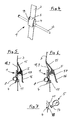
- FIG. 3 is a side view and a sectional view of the retaining element (1) shown in FIG. 2. shown in a closed position.
- the first on the belt (3) longitudinally displaceable arranged holding element (1) is dependent on the Kippwinkel ein its associated Rocker (5) relative to the housing (4) in a closed position of the rocker (5) in a Load-resistant position fixing in any position on the belt (3) can be brought.
- the rocker (5) has two angularly arranged in this embodiment first and second rocker arms (15, 16) having a common pressure actuating surface exhibit.
- the closing position of the rocker (5) is by their positioning in one of the longitudinal course of the belt (3) achieved approximately parallel position (neutral Kippwinkel ein). There is one the rocker (5) associated locking web (17) with a holding element (1) associated Floor (9) with run-up gate (18) for clamping the between locking web (17) and bottom (9) passed through belt (3). In addition comes in this closing position of the Rocker (5) of the second rocker arm (16) on a crosspiece formed on the housing (4) (11) for investment.
- a receptacle (8) for attachment the fixing rod (2) provided.
- the receptacle (8) is designed here as a receiving eye and disposed in a lower portion of the housing (4).
- FIG. 4 is a perspective view of the holding element (1) in an inhibiting position of Rocker (5) shown.
- Fig. 5 is in side view and in sectional view located in this inhibit position Holding element (1) shown.
- this inhibition position of the rocker (5) is in a first Longitudinal direction of the belt (3) a self-locking, at least difficult to move position fixation of the holding element (1) in any position on the belt (3) allows.
- a second longitudinal direction of the belt (3) is a free displacement of the holding element (1) achievable on the belt (3).
- the inhibition position of the rocker (5) is by their positioning in a longitudinal course of the belt (3) slightly inclined position (first tilt angle position) can be achieved. It is the first rocker arm (15) and the locking web (1) of the rocker (5) approximately in a sliding contact brought with the belt (3), whereby a sliding in the one longitudinal direction and a Self-locking in the other longitudinal direction of the belt (3) is possible.
- Fig. 6 is in side view and in sectional view located in a shift position Holding element (1) shown.
- a shift position of the rocker (5) is a position beliebiebige free displacement of the retaining element (1) on the belt (3) in the two Longitudinal causes.
- the displacement position of the rocker (5) is by their positioning in a longitudinal course of the belt (3) more inclined position (second tilt angle position) achievable. It is the first rocker arm (15) into a manually executed force contact with the belt (3) and the locking web (1) of the rocker (5) optionally from the contact with the contact Belt (3) can be brought, whereby a free displacement of the retaining element on the belt (3) allows is.
- the positioning and the locking and unlocking of the retaining element (1) on the belt (3) is advantageously feasible with an operator's hand.
- Fig. 7 is a fragmentary and side view of an enlarged detail of the in a shift position located holding element (1) shown.
- the Arretiersteges (17) of the rocker (5) during a rotational movement of the rocker (5) on a movement path (21) guided in such a way that the end of the Arretiersteges (17) one in the bottom (9) of the housing (4) formed Auflaufkulisse (18) Continuously until complete clamping action from the locking bar (17), belt (3) and runway (18) approach and opposite Direction of rotation of the rocker (5) can remove it.
- the one not shown here, however between the locking web (17) and run-up scenery (18) located belt (3) can thus clamped, touched or released.
- Fig. 8 is a perspective and enlarged view in an inhibiting position located holding element (1) shown.
- the mutually parallel shoulders (10) of the housing (4) have approximately in their length half coaxial through holes (13) for articulated Recording of the end face of the rocker (5) formed pin (14) - as shown in Fig. 11 are - up.
- the end face of the rocker (5) formed pin (14) are here, for example, in about the length of half of the rocker (14) arranged on this.
- Fig. 9 is a perspective and enlarged view of the in a closed position located holding element (1) shown.
- the rocker (5) and the housing (4) have in this Embodiment approximately equal lengths.
- Both rocker arms (15, 16) have a the belt (3) facing, sliding skid-like Autex.
- the housing (4) of the holding element (1) is approximately a U-profile with the bottom (9) and the front side hereby formed and mutually parallel shoulders (10), in spaced from the Floor (9) of the transverse web (11) are bridged.
- This crosspiece (11) limits one end of the housing (4) has a passage (12) for the guided through this belt (3).
- FIG. 10 is a perspective and enlarged view of the housing (4) of the holding element (1) shown.
- the bottom (9) of the housing (4) is for the purpose of positioning the rocker (5) in the sliding position relative to the shoulders (10) of the housing (4) shortened executed.
- a more inclined position of the rocker (5) (second tilt angle position) be made possible with respect to the housing (4).
- the first rocker leg (15) can thus dipping between the two shoulders (10) of the housing (4).
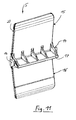
- FIG. 11 is a perspective and enlarged view of the rocker (5) of the holding element (1) shown in a rear view.
- On a back of the rocker (5) is the about at right angles from this projecting, approximately at the level of the pin (14) extending locking web (17) arranged with a in the bottom (9) of the housing (14) formed Auflaufkulisse (18) (FIGS. 7 and 10) and between the run-up gate (18) and locking web (17) passed through Belt (3) corresponds such that on the different Kippwinkel einen the rocker (5) across their closing position, inhibition position and shift position achieved is.
Landscapes
- Engineering & Computer Science (AREA)
- Chemical & Material Sciences (AREA)
- Combustion & Propulsion (AREA)
- Transportation (AREA)
- Mechanical Engineering (AREA)
- Fittings On The Vehicle Exterior For Carrying Loads, And Devices For Holding Or Mounting Articles (AREA)
- Portable Nailing Machines And Staplers (AREA)
Abstract
Description
- Fig. 1
- in perspektivischer Darstellung eine klappbare Schlafliege für ein Fahrerhaus eines Lastkraftwagens mit an Gurten angeordneten Halteelementen,
- Fig. 2
- in perspektivischer Darstellung ein Halteelement gemäß Fig. 1 in einer Schließ- Stellung,
- Fig. 3
- in Seitenansicht und in Schnittdarstellung ein in einer Schließ-Stellung befindliches Halteelement gemäß Fig. 2,
- Fig. 4
- in perspektivischer Darstellung ein Halteelement gemäß Fig. 1 in einer Hemm- Stellung,
- Fig. 5
- in Seitenansicht und in Schnittdarstellung ein in einer Hemm-Stellung befindliches Halteelement gemäß Fig. 4,
- Fig. 6
- in Seitenansicht und in Schnittdarstellung ein in einer Verschiebe-Stellung befindliches Halteelement gemäß Fig. 1,
- Fig. 7
- ausschnittsweise und in Seitenansicht ein vergrößertes Detail eines in einer Verschiebe-Stellung befindlichen Halteelementes gemäß Fig. 6,
- Fig. 8
- in perspektivischer und vergrößerter Darstellung ein in einer Hemm-Stellung befindliches Halteelement gemäß Fig. 5,
- Fig. 9
- in perspektivischer und vergrößerter Darstellung ein in einer Schließ-Stellung befindliches Halteelement gemäß Fig. 3,
- Fig. 10
- in perspektivischer und vergrößerter Darstellung ein Gehäuse des Halteelementes gemäß Fig. 9 und
- Fig. 11
- in perspektivischer und vergrößerter Darstellung der Rückansicht einer Wippe des Halteelementes aemäß Fig. 9.
- 1
- Halteelement
- 2
- Bauteil (z. B. Fixierstange)
- 3
- Gurt
- 4
- Gehäuse
- 5
- Wippe
- 6
- Sicherungsnetz
- 7
- Schlafliege
- 8
- Aufnahmeauge
- 9
- Boden
- 10
- Schultern
- 11
- Quersteg
- 12
- Durchlass
- 13
- Durchgangsbohrung (Koaxial; in Schulter)
- 14
- Zapfen
- 15
- erster Wippenschenkel
- 16
- zweiter Wippenschenkel
- 17
- Arretiersteg
- 18
- Ausmuldung, Auflaufkulisse
- 19
- Auflauframpen
- 20
- Stirnseiten der Wippe
- 21
- Bewegungsbahn
Claims (20)
- Halteelement (1) zur positionsvariablen Halterung von Bauteilen (2) an einem in einem Kraftfahrzeug vorgesehenen Gurt (3), dadurch gekennzeichnet, dass das Halteelement (1) aus einem das Bauteil (2) tragenden und am Gurt (3) längsverschieblich angeordneten Gehäuse (4) sowie einer an diesem kippbar gelagerten Wippe (5) besteht, wobei der Gurt (3) im wesentlichen zwischen Wippe (5) und Gehäuse (4) hindurchgeführt ist, und wobei in Abhängigkeit der Kippwinkelstellung der Wippe (5) am Gehäuse (4)bei einer Schließ-Stellung der Wippe (5) eine lastresistente Positionsfixierung des Halteelementes (1) in einer beliebigen Position auf dem Gurt (3) bewirkt ist,bei einer Hemm-Stellung der Wippe (5) in einer ersten Längsrichtung des Gurtes (3) eine selbsthemmende, wenigstens schwerverschiebbare Positionsfixierung des Halteelementes (1) in beliebiger Position auf dem Gurt (3) und in einer zweiten Längsrichtung des Gurtes (3) eine freie Verschiebbarkeit des Halteelementes (1) auf dem Gurt (3) erzielt ist,bei einer Verschiebe-Stellung der Wippe (5) eine positionsbeliebige freie Verschiebbarkeit des Halteelementes (1) auf dem Gurt (3) in dessen beiden Längsrichtungen bewirkt ist.
- Halteelement nach Anspruch 1, dadurch gekennzeichnet, dass die Schließ-Stellung der Wippe (5) durch ihre Positionierung in einer zum Längsverlauf des Gurtes (3) etwa parallelen Stellung (neutralen Kippwinkelstellung) erzielt ist, wobei ein der Wippe (5) zugehöriger Arretiersteg (17) mit einem dem Halteelement (1) zugehörigen Boden (9) zur Klemmung des zwischen Arretiersteg (17) und Boden (9) hindurchgeführten Gurtes (3) gebracht ist.
- Halteelement nach einem der Ansprüche 1 und 2, dadurch gekennzeichnet, dass die Wippe (5) in ihrer Schließ-Stellung am Gehäuse (4) lösbar verrastet ist.
- Halteelement nach Anspruch 1 bis 3, dadurch gekennzeichnet, dass die Wippe (5) ggf. winklig zueinander verlaufende erste und zweite Wippenschenkel (15,16) aufweist, die eine gemeinsame Druckbetätigungsfläche bilden.
- Halteelement nach Anspruch 1 bis 4, dadurch gekennzeichnet, dass in der Schließ-Stellung der Wippe (5) der zweite Wippenschenkel (16) auf einem am Gehäuse (4) gebildeten Quersteg (11) zur Anlage kommt.
- Halteelement nach einem der Ansprüche 1 und 2, dadurch gekennzeichnet, dass die Hemm-Stellung der Wippe (5) durch ihre Positionierung in einer zum Längsverlauf des Gurtes (3) wenig geneigten Stellung (erste Kippwinkelstellung) erzielt ist, wobei der erste Wippenschenkel (15) und der Arretiersteg (17) der Wippe (5) in etwa in eine Gleitberührung mit dem Gurt (3) gebracht ist.
- Halteelement nach einem der Ansprüche 1 und 2, dadurch gekennzeichnet, dass die Verschiebe-Stellung der Wippe (5) durch ihre Positionierung in einer zum Längsverlauf des Gurtes (3) stärker geneigten Stellung (zweite Kippwinkelstellung) erzielt ist, wobei der erste Wippenschenkel (15) in eine manuell ausgelöste Kraftberührung mit dem Gurt (3) und der Arretiersteg (17) der Wippe (5) ggf. aus der Kontaktberührung mit dem Gurt (3) gebracht ist.
- Halteelement nach einem oder mehreren der vorangegangenen Ansprüche 1 bis 7, dadurch gekennzeichnet, dass die Positionierung sowie die Ver- und Entriegelung des Halteelementes (1) auf dem Gurt (3) mit einer einzelnen Bedienhand erfolgt.
- Halteelement nach einem oder mehreren der vorangegangenen Ansprüche 1 bis 8, dadurch gekennzeichnet, dass das Gehäuse (4) des Halteelementes (1) etwa ein U-Profil mit dem Boden (9) und stirnseitig hieran gebildeten und zueinander parallelen Schultern (10) ist, die in Beabstandung zum Boden (9) von dem Quersteg (11) überbrückt sind, welcher einenendes des Gehäuses (4) einen Durchlass (12) für den durch diesen hindurchgeführten Gurt (3) begrenzt.
- Halteelement nach Anspruch 9, dadurch gekennzeichnet, dass die zueinander parallelen Schultern (10) des Gehäuses (4) in etwa ihrer Längenhälfte koaxiale Durchgangsbohrungen (13) zur gelenkigen Aufnahme von stirnseitig der Wippe (5) gebildeter Zapfen (14) aufweisen.
- Halteelement nach Ansprüche 10, dadurch gekennzeichnet, dass die stirnseitig der Wippe (5) gebildeten Zapfen (14) in etwa der Längenhälfte der Wippe (14) auf dieser angeordnet sind.
- Halteelement nach einem der Ansprüche 9 und 10, dadurch gekennzeichnet, dass auf einer Rückseite des Bodens (9) des Halteelementes (4) oder einer Unterseite des Halteelementes (4) wenigstens eine Aufnahme (8) zur Befestigung des Bauteils (2) gegeben ist.
- Halteelement nach Anspruch 12, dadurch gekennzeichnet, dass das von der Aufnahme (8) des Halteelementes (4) gehaltene Bauteil (2) eine Fixierstange ist, und dass diese Fixierstange (2) ein Sicherungsnetz (6) einer ggf. klappbaren Schlafliege (7) eines Nutzfahrzeuges, bspw. eines Lastkraftwagens trägt.
- Halteelement nach Anspruch 13, dadurch gekennzeichnet, dass jeweils ein Halteelement (1) am wenigstens einen Gurt (3) der ggf. klappbaren Schlafliege (7) eines Lastkraftwagens angeordnet ist.
- Halteelement nach Anspruch 13, dadurch gekennzeichnet, dass die Aufnahme (8) für die Fixierstange (2) als Aufnahmeaugen (8) ausgeführt sind, welche jeweils an den zueinander parallelen Schultern (10) des Gehäuses (4) im Bereich der dem Quersteg (11) gegenüberliegend abgewandten Rückseite des Bodens (9) zur gemeinsamen Aufnahme der Fixierstange (2) vorgesehen sind.
- Halteelement nach einem der Ansprüche 1 bis 15, dadurch gekennzeichnet, dass auf einer Rückseite der Wippe (5) der etwa rechtwinklig von dieser abragende, etwa in Höhe der Zapfen (14) verlaufende Arretiersteg (17) vorgesehen ist, der mit einer im Boden (9) des Gehäuses (14) gebildeten Auflaufkulisse (18) und dem zwischen Auflaufkulisse (18) und Arretiersteg (17) hindurchgeführten Gurt (3) solcherart korrespondiert, dass über die verschiedenen Kippwinkelstellungen der Wippe (5) hinweg deren Schließ-Stellung, Hemm-Stellung und Verschiebe-Stellung erzielt ist.
- Halteelement nach einem der Ansprüche 1 bis 16, dadurch gekennzeichnet, dass ein Ende des Arretiersteges (17) der Wippe (5) bei einer Drehbewegung der Wippe (5) in ihre einzelnen Kippwinkelstellungen auf einer gedachten Bewegungsbahn (21) solcherart geführt ist, dass sich das Ende des Arretiersteges (17) einer im Boden (9) des Gehäuses (4) gebildeten Auflaufkulisse (18) graduell bis zur völligen Klemmwirkung von Arretiersteg (17), Gurt (3) und Auflaufkulisse (18) nähert.
- Halteelement nach einem der Ansprüche 1 bis 17, dadurch gekennzeichnet, dass innenseitig der Schultern (10) des Gehäuses (4) hiervon abragende Auflauframpen (19) gebildet sind, die solcherart mit Stirnseiten (20) der kippfähigen Wippe (5) zusammenwirken, dass diese in ihrer Schließ-Stellung zusätzlich zu ihrer Anlage am Quersteg (11) von den Auflauframpen (19) im Gehäuse (4) verrastet und unter Überwindung einer Übertotpunktwirkung wieder lösbar ist.
- Halteelement nach einem der Ansprüche 1 bis 18, dadurch gekennzeichnet, dass die Wippe (5) und das Gehäuse (4) in etwa gleiche Längen aufweisen, und dass der Boden (9) des Gehäuses (4) zwecks Positionierung der Wippe (5) in der Verschiebe-Stellung gegenüber den Schultern (10) des Gehäuses (4) verkürzt ausgeführt ist, so dass eine stärker geneigte Stellung (zweite Kippwinkelstellung) der Wippe (5) gegenüber dem Gehäuse (4) ermöglicht ist.
- Halteelement nach einem der Ansprüche 1 bis 19, dadurch gekennzeichnet, dass wenigstens der erste Wippenschenkel (15) eine dem Gurt (3) zugewandte, gleitkufenartige Ausendung aufweist.
Applications Claiming Priority (2)
| Application Number | Priority Date | Filing Date | Title |
|---|---|---|---|
| DE2003146876 DE10346876A1 (de) | 2003-10-09 | 2003-10-09 | Halteelement für einen Kraffahrzeuggurt |
| DE10346876 | 2003-10-09 |
Publications (2)
| Publication Number | Publication Date |
|---|---|
| EP1522487A1 true EP1522487A1 (de) | 2005-04-13 |
| EP1522487B1 EP1522487B1 (de) | 2006-06-14 |
Family
ID=34306337
Family Applications (1)
| Application Number | Title | Priority Date | Filing Date |
|---|---|---|---|
| EP20040023013 Expired - Lifetime EP1522487B1 (de) | 2003-10-09 | 2004-09-28 | Halteelement für einen Kraftfahrzeuggurt |
Country Status (2)
| Country | Link |
|---|---|
| EP (1) | EP1522487B1 (de) |
| DE (2) | DE10346876A1 (de) |
Cited By (3)
| Publication number | Priority date | Publication date | Assignee | Title |
|---|---|---|---|---|
| WO2007069947A1 (en) * | 2005-12-13 | 2007-06-21 | Volvo Lastvagnar Ab | Bunk arrangement with partition device |
| EP2022669A3 (de) * | 2007-08-08 | 2009-03-25 | MAN Nutzfahrzeuge Aktiengesellschaft | Arretiervorrichtung, insbesondere für eine Schlafliege eines Nutzfahrzeug-Fahrerhauses |
| CN112078457A (zh) * | 2020-08-07 | 2020-12-15 | 北汽福田汽车股份有限公司 | 车载卧铺总成及车辆 |
Citations (4)
| Publication number | Priority date | Publication date | Assignee | Title |
|---|---|---|---|---|
| US3364529A (en) * | 1965-12-20 | 1968-01-23 | Philip E. Blacher | Rope lock clamp |
| FR2631093A1 (fr) * | 1988-05-09 | 1989-11-10 | Letournel Gilles | Dispositif permettant l'accrochage et le reglage en hauteur d'un objet suspendu a un cordage sur un cable horizontal |
| EP1069031A2 (de) | 1999-07-15 | 2001-01-17 | Klippan Safety Ab | Schlafliegeanordnung in einem Fahrerhaus eines Lastkraftwagens |
| US6292984B1 (en) * | 1999-09-27 | 2001-09-25 | Bradley E. Nelson | Load-support system employing instantaneously adjustable hook |
-
2003
- 2003-10-09 DE DE2003146876 patent/DE10346876A1/de not_active Withdrawn
-
2004
- 2004-09-28 DE DE200450000758 patent/DE502004000758D1/de not_active Expired - Lifetime
- 2004-09-28 EP EP20040023013 patent/EP1522487B1/de not_active Expired - Lifetime
Patent Citations (4)
| Publication number | Priority date | Publication date | Assignee | Title |
|---|---|---|---|---|
| US3364529A (en) * | 1965-12-20 | 1968-01-23 | Philip E. Blacher | Rope lock clamp |
| FR2631093A1 (fr) * | 1988-05-09 | 1989-11-10 | Letournel Gilles | Dispositif permettant l'accrochage et le reglage en hauteur d'un objet suspendu a un cordage sur un cable horizontal |
| EP1069031A2 (de) | 1999-07-15 | 2001-01-17 | Klippan Safety Ab | Schlafliegeanordnung in einem Fahrerhaus eines Lastkraftwagens |
| US6292984B1 (en) * | 1999-09-27 | 2001-09-25 | Bradley E. Nelson | Load-support system employing instantaneously adjustable hook |
Cited By (4)
| Publication number | Priority date | Publication date | Assignee | Title |
|---|---|---|---|---|
| WO2007069947A1 (en) * | 2005-12-13 | 2007-06-21 | Volvo Lastvagnar Ab | Bunk arrangement with partition device |
| US7823962B2 (en) | 2005-12-13 | 2010-11-02 | Volvo Lastvagnar Ab | Bunk arrangement with partition device |
| EP2022669A3 (de) * | 2007-08-08 | 2009-03-25 | MAN Nutzfahrzeuge Aktiengesellschaft | Arretiervorrichtung, insbesondere für eine Schlafliege eines Nutzfahrzeug-Fahrerhauses |
| CN112078457A (zh) * | 2020-08-07 | 2020-12-15 | 北汽福田汽车股份有限公司 | 车载卧铺总成及车辆 |
Also Published As
| Publication number | Publication date |
|---|---|
| EP1522487B1 (de) | 2006-06-14 |
| DE502004000758D1 (de) | 2006-07-27 |
| DE10346876A1 (de) | 2005-05-04 |
Similar Documents
| Publication | Publication Date | Title |
|---|---|---|
| DE3420574C2 (de) | ||
| DE60021452T2 (de) | Blockiervorrichtung | |
| DE3890701C2 (de) | System für einen auf einem Fahrzeug montierten Lastenträger für ein Fahrrad oder eine andere Last | |
| DE19513520C1 (de) | Kraftfahrzeug mit einer Heckklappe, insbesondere für Mehrzweck- oder Kombiwagen | |
| DE19654395C1 (de) | Nocken zur lösbaren Verriegelung eines Bauteils, insbesondere an einem Kraftfahrzeugsitz | |
| DE60200799T2 (de) | Rettungsfahrzeug | |
| DE3911165C2 (de) | Sitzverschiebe-Vorrichtung | |
| DE102020105202A1 (de) | Vorrichtung zur translatorischen und rotatorischen Bewegung eines Gegenstands relativ zu einer Trägerplatte | |
| EP1107878B1 (de) | Befestigungsvorrichtung für einen kindersitz | |
| DE19920386C2 (de) | Lager für eine umklappbare Rückenlehne | |
| DE2365921A1 (de) | Vorrichtung zum festlegen von unter einem flugzeug mitzufuehrenden lasten | |
| EP0831001A1 (de) | Hängerunge | |
| EP1522487A1 (de) | Halteelement für einen Kraftfahrzeuggurt | |
| DE3426207A1 (de) | Vorrichtung zur Höhenverstellung eines oberen Haltepunktes eines Sicherheitsgurtsystems | |
| DE69200109T2 (de) | Einrichtung zum Verkeilen von Fahrzeugen, die auf Böden von Transportanhängern oder Eisenbahnwaggons vorgesehen sind. | |
| DE10338723B4 (de) | Vorrichtung zum Transport von Gegenständen an einem Fahrzeugheck | |
| DE1940861C3 (de) | Abschließbarer Schiträger für Kraftfahrzeuge | |
| DE69903130T2 (de) | Ausklappbarer bügeltisch | |
| EP2011688B1 (de) | Adapter für ein Kraftfahrzeug-Haltesystem | |
| DE19915315C2 (de) | Neigungsverstellvorrichtung für eine Fondsitzlehne | |
| DE10201622B4 (de) | Vorrichtung zum Verankern einer Last an einem Fahrzeugboden | |
| DE10058906C2 (de) | Sitzmodul | |
| DE69209512T2 (de) | Faltbarer gepäckwagen | |
| DE19643806C2 (de) | Kindersportwagen mit einem von seinem Fahrgestell lösbaren Sitz | |
| DE60102620T2 (de) | Verbindungsvorrichtung für Befestigungsstangen an einem Kraftfahrzeug |
Legal Events
| Date | Code | Title | Description |
|---|---|---|---|
| PUAI | Public reference made under article 153(3) epc to a published international application that has entered the european phase |
Free format text: ORIGINAL CODE: 0009012 |
|
| AK | Designated contracting states |
Kind code of ref document: A1 Designated state(s): AT BE BG CH CY CZ DE DK EE ES FI FR GB GR HU IE IT LI LU MC NL PL PT RO SE SI SK TR |
|
| AX | Request for extension of the european patent |
Extension state: AL HR LT LV MK |
|
| 17P | Request for examination filed |
Effective date: 20050427 |
|
| GRAP | Despatch of communication of intention to grant a patent |
Free format text: ORIGINAL CODE: EPIDOSNIGR1 |
|
| AKX | Designation fees paid |
Designated state(s): DE FR IT SE |
|
| GRAS | Grant fee paid |
Free format text: ORIGINAL CODE: EPIDOSNIGR3 |
|
| GRAA | (expected) grant |
Free format text: ORIGINAL CODE: 0009210 |
|
| AK | Designated contracting states |
Kind code of ref document: B1 Designated state(s): DE FR IT SE |
|
| REF | Corresponds to: |
Ref document number: 502004000758 Country of ref document: DE Date of ref document: 20060727 Kind code of ref document: P |
|
| REG | Reference to a national code |
Ref country code: SE Ref legal event code: TRGR |
|
| ET | Fr: translation filed | ||
| PLBE | No opposition filed within time limit |
Free format text: ORIGINAL CODE: 0009261 |
|
| STAA | Information on the status of an ep patent application or granted ep patent |
Free format text: STATUS: NO OPPOSITION FILED WITHIN TIME LIMIT |
|
| 26N | No opposition filed |
Effective date: 20070315 |
|
| REG | Reference to a national code |
Ref country code: FR Ref legal event code: CD |
|
| REG | Reference to a national code |
Ref country code: DE Ref legal event code: R081 Ref document number: 502004000758 Country of ref document: DE Owner name: MAN TRUCK & BUS AG, DE Free format text: FORMER OWNER: MAN NUTZFAHRZEUGE AG, 80995 MUENCHEN, DE Effective date: 20110518 |
|
| REG | Reference to a national code |
Ref country code: FR Ref legal event code: PLFP Year of fee payment: 13 |
|
| REG | Reference to a national code |
Ref country code: FR Ref legal event code: PLFP Year of fee payment: 14 |
|
| REG | Reference to a national code |
Ref country code: FR Ref legal event code: PLFP Year of fee payment: 15 |
|
| REG | Reference to a national code |
Ref country code: DE Ref legal event code: R081 Ref document number: 502004000758 Country of ref document: DE Owner name: MAN TRUCK & BUS SE, DE Free format text: FORMER OWNER: MAN TRUCK & BUS AG, 80995 MUENCHEN, DE |
|
| PGFP | Annual fee paid to national office [announced via postgrant information from national office to epo] |
Ref country code: IT Payment date: 20230920 Year of fee payment: 20 |
|
| PGFP | Annual fee paid to national office [announced via postgrant information from national office to epo] |
Ref country code: SE Payment date: 20230926 Year of fee payment: 20 Ref country code: FR Payment date: 20230926 Year of fee payment: 20 Ref country code: DE Payment date: 20230928 Year of fee payment: 20 |
|
| REG | Reference to a national code |
Ref country code: DE Ref legal event code: R071 Ref document number: 502004000758 Country of ref document: DE |
|
| REG | Reference to a national code |
Ref country code: SE Ref legal event code: EUG |