EP2011688B1 - Adapter für ein Kraftfahrzeug-Haltesystem - Google Patents
Adapter für ein Kraftfahrzeug-Haltesystem Download PDFInfo
- Publication number
- EP2011688B1 EP2011688B1 EP08011495A EP08011495A EP2011688B1 EP 2011688 B1 EP2011688 B1 EP 2011688B1 EP 08011495 A EP08011495 A EP 08011495A EP 08011495 A EP08011495 A EP 08011495A EP 2011688 B1 EP2011688 B1 EP 2011688B1
- Authority
- EP
- European Patent Office
- Prior art keywords
- casing
- rotary element
- hook
- adapter according
- adapter
- Prior art date
- Legal status (The legal status is an assumption and is not a legal conclusion. Google has not performed a legal analysis and makes no representation as to the accuracy of the status listed.)
- Not-in-force
Links
- 238000002347 injection Methods 0.000 claims 1
- 239000007924 injection Substances 0.000 claims 1
- 238000007373 indentation Methods 0.000 abstract 1
- 238000006073 displacement reaction Methods 0.000 description 8
- 238000003780 insertion Methods 0.000 description 5
- 230000037431 insertion Effects 0.000 description 5
- 238000000926 separation method Methods 0.000 description 3
- 230000006835 compression Effects 0.000 description 1
- 238000007906 compression Methods 0.000 description 1
- 230000003247 decreasing effect Effects 0.000 description 1
- 230000009977 dual effect Effects 0.000 description 1
- 230000000694 effects Effects 0.000 description 1
- 239000000463 material Substances 0.000 description 1
- 239000007769 metal material Substances 0.000 description 1
- 238000000034 method Methods 0.000 description 1
Images

Classifications
-
- B—PERFORMING OPERATIONS; TRANSPORTING
- B60—VEHICLES IN GENERAL
- B60P—VEHICLES ADAPTED FOR LOAD TRANSPORTATION OR TO TRANSPORT, TO CARRY, OR TO COMPRISE SPECIAL LOADS OR OBJECTS
- B60P7/00—Securing or covering of load on vehicles
- B60P7/06—Securing of load
- B60P7/135—Securing or supporting by load bracing means
- B60P7/15—Securing or supporting by load bracing means the load bracing means comprising a movable bar
-
- B—PERFORMING OPERATIONS; TRANSPORTING
- B60—VEHICLES IN GENERAL
- B60P—VEHICLES ADAPTED FOR LOAD TRANSPORTATION OR TO TRANSPORT, TO CARRY, OR TO COMPRISE SPECIAL LOADS OR OBJECTS
- B60P7/00—Securing or covering of load on vehicles
- B60P7/06—Securing of load
- B60P7/08—Securing to the vehicle floor or sides
- B60P7/0807—Attachment points
- B60P7/0815—Attachment rails or trellis
Definitions
- the invention relates to an adapter for a motor vehicle holding system according to the preamble of patent claim 1.
- an adapter for a motor vehicle holding system in the region of a trunk of the motor vehicle which has a housing and clamping elements, so that the housing can be fixed in a clamping position on a mounting rail mounted on the motor vehicle.
- the adapter has an O-shaped lashing strap, so that cargo can be lashed down using belts.
- an adapter for fixing conveyed to a mounted in a motor vehicle retaining rail is known.
- a locking pin which engages in a recess of the mounting rail and thus fixes the adapter.
- the adapter also has a recess on, which serves to receive a vertical rod of the conveyed.
- an insertion opening is formed, wherein the insertion opening can be at least partially closed by means of a clamping lever.
- Object of the present invention is to develop an adapter for a motor vehicle-holding system such that the handling or ease of use with respect to the attachment of luggage racks, nets, bags and the like improved.
- the invention has the features of claim 1.
- the particular advantage of the invention is that the provision of mounting options on the adapter is improved by providing a pivotable functional hook.
- a clamping position of the adapter of the function hooks can be swung out of an extension plane of a housing of the adapter, so that the mounting location of fasteners, such as belt, rods, etc. of the same in the clamping position of the adapter is changeable. This increases the variability of the adapter with respect to the attachment or fixing of fasteners on the same.
- the invention has a spatial separation between a manually operable rotary member, by means of which the adapter can be brought into the clamping position and in the non-clamping position, and the function hook, so that easy to use a defined spatial separation between the Actuating means for fixing the adapter to the support rail of the motor vehicle on the one hand and for fixing fasteners on the adapter on the other hand is given.
- the adapter can be manipulated by means of the insertable into the recess of the rotary member holding rod.
- the adapter has a slot for a belt receiving, which extends in extension to a pivot axis about which the functional hook is pivotable.
- the slot thus forms a spatial separation between the central portion of the housing in which the rotary member is located, and an outer portion of the housing in which the function hook is located.
- the slot can be arranged to save space.
- the support rod is connected via a ball joint with the knob, so that the support rod is easy to use by pivoting about the pivot point of the ball joint in a three-dimensional space can be aligned.
- the housing is integrally connected in a adjacent to the rotary member lower portion with a hook on which the support rod is detachably connected.
- a further functional component is provided for connection to fastening means designed as a holding rod.
- the invention thus makes it possible to provide functional components for fixing fastening means over the entire surface of a housing of the adapter.
- a central portion of the housing can be mounted at different heights a holding rod.
- an outer section of the housing can be added at different heights straps, nets or bags are hung.
- the function hook is fixed in the folded-in position in which it runs along the plane of extent of the housing, and in the unfolded position in which it is at an angle to the plane of extension of the housing.
- one or more defined Festlegpositionen be specified.
- the function hook on the edge side at least one support end and / or a rotation stop, so that the function hook is obtained in the retracted position and in the unfolded position respectively in a defined position to the housing.
- the rotary member is movable about a plane perpendicular to the extension plane of the housing axis of rotation, wherein the rotary member for moving the housing in the clamping position acting on adjusting means such that in a rotational position of the rotary element, a first clamping element in the transverse direction to the axis of rotation of the rotary member presses against the retaining rail and a second clamping element in the axial direction of the rotary member presses against the retaining rail.
- this can be done by the adapter along the support rail without applying a holding force of a clamping element counteracting force.
- the clamping element In the displacement position of the adapter, the clamping element is only in an abutment position on the retaining rail, without a clamping force acting on the retaining rail.
- Easy to use the movement of the adapter from a displacement position into a clamping position and vice versa by rotating the rotary member about a rotation axis can be effected, wherein the rotation axis is perpendicular to the support rail.
- clamping elements act in the transverse direction to the axis of rotation of the rotary member and in the axial direction of the rotary member, a secure fixation of the adapter can be effected in the clamping position.
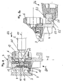
- An inventive adapter 1 is used for attachment of handrails 2, luggage racks, nets, bags and the like on a support rail 3, which is mounted in a luggage compartment of a motor vehicle on an upright inner wall.
- the adapter 1 has a substantially plate-shaped housing 4, which is mounted in a central portion 5 by means of a rotary member 6 releasably and slidably on the double-T-retaining rail 3.
- the housing 4 has a pincer-shaped projection 7, which is placed around a protruding from the body wall of the motor vehicle front portion of the support rail 3.
- a detent element 8 designed as a clamping element with its nose 9, the narrow side of the front portion of the support rail.
- the rotary member 6 is formed as a trained as an actuator knob, which is about an axis of rotation 10th is mounted in the housing 4.
- the knob 6 is rotatably connected to an eccentric 11 having a circumferentially extending eccentric surface.
- the eccentric Upon rotation of the knob 6 from a displacement position in a clamping position, for example, 45 °, the eccentric exerts a force on a leaf spring 12, so that the latching hook 8 is moved in a first transverse direction Q1 laterally to the support rail 3 in the clamping position and thus the housing 4 clamped to the support rail 3.
- the eccentric 11 has an axially extending cam 13, which acts upon rotation of the knob 6 in a second transverse direction Q2 on an axially displaceable pressure member 14 which acts on a resiliently in the axial direction of pressure plate 15 (further clamping element).
- the pressure plate 15 is thus pressed in the clamping position on an upper side or flat side of the retaining rail 3. Since the pressure plate 15 is resiliently designed in the region of the pressure piece 14, this process can always be repeated without the clamping force on the holding rail 3 decreasing.
- the knob 6 is in a zero position in which the clear distance between the projection 7 of the housing 4 and the nose 9 of the latching hook 8 is greater than the transverse extent of the front portion of the support rail 3rd Auf In this way, the adapter 1 can be placed on the support rail 3 and spent by rotation of the knob 6 by 45 ° in a displacement position in which the nose 9 of the latching hook 8 engages behind the front portion of the support rail 3 and the adapter 1 along the support rail. 3 is displaceable.
- the knob 6 has reached the displacement position when by means of a head of the knob 6 in a recess mounted detent sleeve 16 by means of a compression spring, not shown in a recess of the housing 4 engages and thus locks the knob 6.
- the eccentric 11 serves as Drehzisumwandlungsorgan, the circumferential eccentric surfaces serve as a transverse movement connection for acting on the latching hook 8 and the cam 13 as Axialmonysan gleich for acting on the pressure member 14.
- the nose 9 of the latching hook 8 is only on the support rail 3, without exerting a clamping force.
- the pressure plate 15 is also in this displacement position without clamping effect on the support rail 3, wherein a corrugated plate 18 between the pressure plate 15 and the pressure member 14 provides for a tolerance compensation.
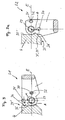
- the rotary element 6 serves as a functional part, since it has a recess 19 into which a head 20 provided with an end of the support rod 2 can engage, so that the support rod 2 is connected via a ball joint with the rotary member 6.
- the support rod 2 can thus be pivoted in the mounting position in the horizontal and / or vertical direction about a center of the head 20.
- the rotary element 6 thus has a dual function. On the one hand, it serves to lock the adapter 1 to the support rail 3 and the other to receive one end of the support rod 2.
- a hook 22 is arranged as a functional part, which is positively connected with a hook-shaped end 23 of a support rod 24, in particular latching.
- the support rod 24 For mounting the support rod 24 to the housing 4, the same is suspended by partially engaging around an end 22 'of the hook 22 through the hook-shaped end 23 and locked by engaging behind a spring-biased clamping member 25 of the support rod 24 to the hook 22.
- the hook 22 protrudes from the housing 4 on a side facing away from the retaining rail 3 and extends substantially below the rotary element 6.
- a respective fastening hook 27 is arranged as a functional part, which extends rigidly in an extension plane E of the housing 4.
- a pivotable function hook 28 is in each case arranged around a pivot axis 29 from a folded position S1 in accordance with FIG. 3 in which it is located in the extension plane E of the housing 4, in an unfolded position S2 according to FIG FIG. 3a is pivotable, in which the function hook 28 is at an angle to the plane of extension E of the housing 4.
- the function hook 28 is fixed in the folded position S1 and in the unfolded position S2 detent.
- the function hook 28 has two offset by the pivot angle ⁇ and arranged at an equal distance A to the pivot axis 29 first recess 30 and second recess 31, in each of the retracted position S1 and in the unfolded position S2 is a spring-biased and latching engages in a bore 33 of the housing 4 mounted bolt 32.
- the axis of the bolt 32 is arranged parallel to the pivot axis 29. Since the first recess 30 and the second recess 31 are arranged at a right angle offset from the pivot axis 29, the pivot angle ⁇ in the present embodiment is 90 °.
- the swivel angle can also be larger or smaller, or several swivel angles can be specified by increasing the number of recesses.
- the function hook 28 is supported in the retracted position S1 by means of a Supporting 34 surface on a rear part 35 'of a wall 35 of the housing 4 from.
- the functional hook 28 is in the unfolded position S2 via a rotation stopper 36 on a front part 35 "of the wall 35.
- Advantageously defined end positions of the functional hook 28 can thus be effected.
- the pivot axis 29 is arranged perpendicular to the axis of rotation 10.
- the pivot axis 29 is arranged perpendicular to a longitudinal center plane L of the housing 4.
- a slot 38 is provided in a region between the central portion 5 and the outer portion 26 for receiving a belt.
- the slot 38 thus serves as another functional part for attachment of luggage etc.
- the slot 38 extends over half the height of the housing 4 and allows the insertion of a strap, not shown, easy to use from an upper side of the housing 4 ago.
- the spring-biased pin 32 engages with its dome 40 in the first recess 30.
- the function hook 28 is clipped with its shaft 41 and its collar 42 in the housing 4 and rotatably mounted in a bore 43. Above this bore 43, the slot 38 extends to receive a belt.
- the adapter 1 may be made of a plastic or a metal material.
Description
- Die Erfindung betrifft einen Adapter für ein Kraftfahrzeug-Haltesystem nach dem Oberbegriff des Patentanspruchs 1.
- Aus der
DE 20 2006 010 599 U1 ist ein Adapter für ein Kraftfahrzeug-Haltesystem im Bereich eines Kofferraums des Kraftfahrzeuges bekannt, das ein Gehäuse und Klemmelemente aufweist, so dass das Gehäuse in einer Klemmstellung an einer am Kraftfahrzeug montierten Halteschiene festlegbar ist. Das Adapter weist einen O-förmigen Verzurrbügel auf, so dass unter Verwendung von Bändern Ladegüter verzurrt werden können. - Aus der
DE 203 02 929 U1 ist ein Adapter zur Festlegung von Fördergut an einer in einem Kraftfahrzeug montierten Halteschiene bekannt. Zur Befestigung des Adapters an der Schiene dient ein Rastbolzen, der in eine Rastausnehmung der Befestigungsschiene eingreift und den Adapter somit festlegt. Der Adapter weist darüber hinaus eine Ausnehmung auf, die zur Aufnahme eines Vertikalstabs des Förderguts dient. Zum Einsetzen des Vertikalstabs in die Ausnehmung ist eine Einsetzöffnung ausgebildet, wobei die Einsetzöffnung mittels eines Klemmhebels zumindest teilweise verschlossen werden kann. Beim Verschließen der Einsetzöffnung ist der Vertikalstab des Förderguts in der Ausnehmung festgelegt. - Aufgabe der vorliegenden Erfindung ist es, ein Adapter für ein Kraftfahrzeug-Haltesystem derart weiterzubilden, dass die Handhabung bzw. Bedienungsfreundlichkeit hinsichtlich der Befestigung von Gepäckstangen, Netzen, Taschen und dergleichen verbessert.
- Zur Lösung dieser Aufgabe weist die Erfindung die Merkmale des Patentanspruchs 1 auf.
- Der besondere Vorteil der Erfindung besteht darin, dass die Bereitstellung von Befestigungsmöglichkeiten an dem Adapter durch Vorsehen eines verschwenkbaren Funktionshakens verbessert wird. In einer Klemmstellung des Adapters kann der Funktionshaken aus einer Erstreckungsebene eines Gehäuses des Adapters herausgeschwenkt werden, so dass der Anbringungsort von Befestigungsmitteln, wie Gurt, Stangen etc. an dem Adapter in der Klemmstellung desselben veränderbar ist. Hierdurch vergrößert sich die Variabilität des Adapters hinsichtlich der Anbringung bzw. Festlegung von Befestigungsmitteln an demselben. Vorteilhaft weist die Erfindung eine räumliche Trennung zwischen einem manuell zu betätigendem Drehelement, mittels dessen der Adapter in die Klemmstellung und in die Nichtklemmstellung verbringbar ist, und dem Funktionshaken auf, so dass bedienungsfreundlich eine definierte räumliche Trennung zwischen den Betätigungsmitteln für die Festlegung des Adapters an der Halteschiene des Kraftfahrzeugs einerseits und für das Festlegen von Befestigungsmitteln an dem Adapter andererseits gegeben ist. Weiterhin kann der Adapter mittels der in die Vertiefung des Drehelements einsetzbaren Haltestange handhabungsfreundlich betätigt werden.
- Nach einer Weiterbildung der Erfindung weist der Adapter einen Schlitz für eine Gurtaufnahme auf, die sich in Verlängerung zu einer Schwenkachse erstreckt, um die der Funktionshaken schwenkbar ist. Der Schlitz bildet somit eine räumliche Trennung zwischen dem zentralen Abschnitt des Gehäuses, in dem sich das Drehelement befindet, und einem äußeren Abschnitt des Gehäuses, in dem sich der Funktionshaken befindet. Vorteilhaft kann somit der Schlitz Platz sparend angeordnet sein.
- Nach einer Weiterbildung der Erfindung ist die Haltestange über ein Kugelgelenk mit dem Drehknopf verbunden, so dass die Haltestange bedienungsfreundlich durch Verschwenken um den Schwenkpunkt des Kugelgelenkes in einem dreidimensionalen Raum ausrichtbar ist.
- Nach einer Weiterbildung der Erfindung ist das Gehäuse in einem zu dem Drehelement benachbarten unteren Bereich einstückig mit einem Haken verbunden, an dem die Haltestange lösbar verbindbar ist. Vorteilhaft wird neben der Aufnahme des Drehknopfs ein weiteres Funktionsbauteil bereitgestellt zur Verbindung mit als eine Haltestange ausgebildeten Befestigungsmitteln.
- Die Erfindung ermöglicht somit die Bereitstellung von Funktionsbauteilen zur Festlegung von Befestigungsmitteln über die gesamte Fläche eines Gehäuses des Adapters. In einem zentralen Abschnitt des Gehäuses kann in unterschiedlicher Höhe eine Haltestange angebracht werden. In einem äußeren Abschnitt des Gehäuses können in unterschiedlichen Höhen Gurte aufgenommen, Netze bzw. Taschen eingehängt werden. Hierdurch wird ein Adapter geschaffen, das universell zum Festlegen von Befestigungsmitteln bzw. Einhängemitteln geeignet ist.
- Nach einer Weiterbildung der Erfindung ist der Funktionshaken in der eingeklappten Stellung, in der er entlang der Erstreckungsebene des Gehäuses verläuft, und in der ausgeklappten Stellung, in der er sich in einem Winkel zu der Erstreckungsebene des Gehäuses befindet, rastend festgelegt. Vorteilhaft können hierdurch eine oder mehrere definierte Festlegpositionen vorgegeben werden.
- Nach einer Weiterbildung der Erfindung weist der Funktionshaken randseitig mindestens ein Abstützende und/oder einen Drehanschlag auf, so dass der Funktionshaken in der eingeklappten Stellung und in der ausgeklappten Stellung jeweils in einer definierten Position zu dem Gehäuse erhalten ist.
- Nach einer Weiterbildung der Erfindung ist das Drehelement um eine senkrecht zur Erstreckungsebene des Gehäuses verlaufende Drehachse bewegbar, wobei das Drehelement zum Verbringen des Gehäuses in die Klemmstellung auf Stellmittel derart einwirkt, dass in einer Drehstellung des Drehelementes ein erstes Klemmelement in Querrichtung zu der Drehachse des Drehelementes gegen die Halteschiene drückt und ein zweites Klemmelement in Axialrichtung des Drehelementes gegen die Halteschiene drückt. Vorteilhaft kann hierdurch der Adapter entlang der Halteschiene ohne Aufwenden einer der Haltekraft eines Klemmelementes entgegenwirkenden Kraft erfolgen. In der Verschiebestellung des Adapters befindet sich das Klemmelement lediglich in einer Anlageposition an der Halteschiene, ohne das eine Klemmkraft auf die Halteschiene wirkt. Bedienungsfreundlich kann das Verbringen des Adapters von einer Verschiebestellung in eine Klemmstellung und umgekehrt durch Verdrehen des Drehelementes um eine Drehachse bewirkt werden, wobei die Drehachse senkrecht zur Halteschiene verläuft. Dadurch, dass Klemmelemente in Querrichtung zur Drehachse des Drehelementes sowie in Axialrichtung des Drehelementes wirken, kann eine sichere Fixierung des Adapters in der Klemmstellung bewirkt werden.
- Ein Ausführungsbeispiel der Erfindung wird nachfolgend anhand der Zeichnungen näher erläutert.
- Es zeigen:
- Figur 1
- eine Vorderansicht eines Adapters,
- Figur 2
- einen Vertikalschnitt durch den an einer Halteschiene eines Kraftfahrzeugs montierten Adapter entlang der Linie II-II in
Figur 1 , das im Bereich eines zentralen Drehknopfes mit einer Haltestange verbunden ist, - Figur 2a
- einen teilweisen Vertikalschnitt durch den Adapter entlang der Linie II-II in
Figur 1 , der in einem unteren Bereich über einen Haken mit einer Haltestange verbunden ist, - Figur 3
- einen Schnitt durch den Adapter gemäß
Figur 1 entlang der Schnittlinie III-III in einer eingeklappten Stellung eines Befestigungshakens (Taschenhaken) und - Figur 3a
- einen horizontalen Schnitt durch den Adapter gemäß
Figur 1 entlang der Schnittlinie III-III in einer ausgeklappten Stellung des Befestigungshakens (Taschenhaken). - Ein erfindungsgemäßer Adapter 1 dient zur Befestigung von Haltestangen 2, Gepäckstangen, Netzen, Taschen und dergleichen an einer Halteschiene 3, die in einem Gepäckraum eines Kraftfahrzeugs an einer aufrechten Innenwand montiert ist.
- Der Adapter 1 weist ein im Wesentlichen plattenförmiges Gehäuse 4 auf, das in einem zentralen Abschnitt 5 mittels eines Drehelementes 6 lösbar und verschiebbar an der Doppel-T-Halteschiene 3 gehaltert ist. Das Gehäuse 4 weist einen zangenförmigen Vorsprung 7 auf, der um einen von der Karosseriewand des Kraftfahrzeugs abstehenden vorderen Abschnitt der Halteschiene 3 herumgelegt ist. Auf einer gegenüberliegenden Seite der Halteschiene 3 hintergreift ein als Rasthaken 8 ausgebildetes Klemmelement mit seiner Nase 9 die Schmalseite des vorderen Abschnitts der Halteschiene 3.
- Das Drehelement 6 ist als ein als Betätigungselement ausgebildeter Drehknopf ausgebildet, der um eine Drehachse 10 in dem Gehäuse 4 gelagert ist. Der Drehknopf 6 ist drehfest mit einem Exzenter 11 verbunden, der eine in Umfangsrichtung verlaufende Exzenterfläche aufweist. Bei Verdrehung des Drehknopfes 6 aus einer Verschiebestellung in eine Klemmstellung um beispielsweise 45° übt die Exzenterfläche eine Kraft auf eine Blattfeder 12 auf, so dass der Rasthaken 8 in einer ersten Querrichtung Q1 seitlich zu der Halteschiene 3 in die Klemmposition bewegt wird und somit das Gehäuse 4 an der Halteschiene 3 einspannt.
- Der Exzenter 11 weist einen axial verlaufenden Nocken 13 auf, der beim Verdrehen des Drehknopfes 6 in einer zweiten Querrichtung Q2 auf ein als axial verschiebliches Druckstück 14 wirkt, das auf eine in axialer Richtung federnd ausgelegte Druckplatte 15 (weiteres Klemmelement) wirkt. Die Druckplatte 15 wird somit in der Klemmstellung auf eine Oberseite bzw. Flachseite der Halteschiene 3 gedrückt. Da die Druckplatte 15 im Bereich des Druckstücks 14 federnd ausgelegt ist, kann dieser Vorgang immer wiederholt werden, ohne dass die Klemmkraft auf der Halteschiene 3 nachlässt.
- Zur Montage des Adapters 1 an der Halteschiene 3 befindet sich der Drehknopf 6 in einer Nullstellung, in der der lichte Abstand zwischen dem Vorsprung 7 des Gehäuses 4 und der Nase 9 des Rasthakens 8 größer ist als die Quererstreckung des vorderen Bereiches der Halteschiene 3. Auf diese Weise kann der Adapter 1 auf die Halteschiene 3 aufgesetzt werden und mittels Verdrehung des Drehknopfes 6 um 45° in eine Verschiebestellung verbracht werden, in der die Nase 9 des Rasthakens 8 den vorderen Bereich der Halteschiene 3 hintergreift und der Adapter 1 entlang der Halteschiene 3 verschiebbar ist.
- Der Drehknopf 6 hat die Verschiebestellung erreicht, wenn mittels einer am Kopf des Drehknopfes 6 in einer Ausnehmung gelagerte Rasthülse 16 mittels einer nicht dargestellten Druckfeder in einer Ausnehmung des Gehäuses 4 einrastet und somit den Drehknopf 6 arretiert.
- Durch weiteres Verdrehen des Drehknopfes 6 um 45° in die Klemmstellung werden zum einen der Rasthaken 8 und zum anderen die axial bewegliche Druckplatte 15 in die Klemmposition verbracht.
- In der Klemmstellung wird der Drehknopf 6 durch einen Raststift gehalten, so dass ein unbeabsichtigtes Lösen des Drehknopfes 6 und somit Lockern des Gehäuses 4 verhindert wird.
- Der Exzenter 11 dient als Drehbewegungsumwandlungsorgan, wobei die umlaufenden Exzenterflächen als Querbewegungsanschluss zur Beaufschlagung des Rasthakens 8 und der Nocken 13 als Axialbewegungsanschluss zur Beaufschlagung des Druckstückes 14 dienen.
- In der Verschiebestellung liegt die Nase 9 des Rasthakens 8 lediglich an der Halteschiene 3 an, ohne eine Klemmkraft auszuüben. Die Druckplatte 15 liegt in dieser Verschiebestellung ebenfalls ohne Klemmwirkung an der Halteschiene 3 an, wobei eine Wellscheibe 18 zwischen der Druckplatte 15 und dem Druckstück 14 für einen Toleranzausgleich sorgt.
- In dem zentralen Abschnitt 5 des Gehäuses 4 sind Funktionsteile zur lösbaren Verbindung mit der Haltestange 2 angeordnet. Zum einen dient das Drehelement 6 als Funktionsteil, da es eine Vertiefung 19 aufweist, in die ein mit einem Kopf 20 versehenes Ende der Haltestange 2 eingreifen kann, so dass die Haltestange 2 über ein Kugelgelenk mit dem Drehelement 6 verbunden ist. Die Haltestange 2 kann somit in der Montageposition in horizontaler und/oder vertikaler Richtung um einen Mittelpunkt des Kopfes 20 verschwenkt werden. Das Drehelement 6 weist somit eine Doppelfunktion auf. Zum einen dient es zur Arretierung des Adapters 1 an der Halteschiene 3 und zum anderen zur Aufnahme eines Endes der Haltestange 2. Dadurch, dass das Ende der Haltestange 2 drehfest in der Vertiefung 19 des Drehelementes 6 gehalten ist, kann mittels Verdrehung der Haltestange 2 das Drehelement 6 in die den Adapter 1 an der Halteschiene 3 arretierende Klemmstellung und/oder in die den Adapter 1 entlang der Halteschiene 3 verschiebbare Verschiebestellung verbracht werden.
- In einem unteren Bereich 21 des zentralen Abschnitts 5 ist als Funktionsteil ein Haken 22 angeordnet, der mit einem hakenförmigen Ende 23 einer Haltestange 24 formschlüssig, insbesondere rastend verbindbar ist. Zur Montage der Haltestange 24 an dem Gehäuse 4 wird dieselbe unter teilweisem Umgreifen eines Endes 22' des Hakens 22 durch das hakenförmige Ende 23 eingehängt und durch Hintergreifen eines federvorgespannten Klemmteils 25 der Haltestange 24 an dem Haken 22 arretiert.
- Der Haken 22 ragt auf einer der Halteschiene 3 abgewandten Seite von dem Gehäuse 4 ab und erstreckt sich im Wesentlichen unterhalb des Drehelementes 6.
- An gegenüberliegenden Seiten des zentralen Abschnitts 5 des Gehäuses 4 schließt sich jeweils ein äußerer Abschnitt 26 des Gehäuses 4 an, der jeweils über Funktionsteile zum Befestigen von Gurten, Bändern etc. aufweist. In einem oberen Bereich des äußeren Abschnitts 26 ist als Funktionsteil jeweils ein Befestigungshaken 27 angeordnet, der sich starr in einer Erstreckungsebene E des Gehäuses 4 erstreckt. In einem unteren Bereich des äußeren Abschnitts 26 ist jeweils ein schwenkbarer Funktionshaken 28 angeordnet, der um eine Schwenkachse 29 aus einer eingeklappten Stellung S1 gemäß
Figur 3 , in der er sich in der Erstreckungsebene E des Gehäuses 4 befindet, in eine ausgeklappte Stellung S2 gemäßFigur 3a verschwenkbar ist, in der sich der Funktionshaken 28 in einem Winkel zu der Erstreckungsebene E des Gehäuses 4 befindet. Der Funktionshaken 28 ist in der eingeklappten Stellung S1 und in der ausgeklappten Stellung S2 rastend festgelegt. Zu diesem Zweck weist der Funktionshaken 28 zwei um den Schwenkwinkel α versetzt und in einem gleichen Abstand A zur Schwenkachse 29 angeordnete erste Aussparung 30 und zweite Aussparung 31 auf, in die jeweils in der eingeklappten Stellung S1 bzw. in der ausgeklappten Stellung S2 ein federvorgespannter und rastend in einer Bohrung 33 des Gehäuses 4 gelagerter Bolzens 32 eingreift. Die Achse des Bolzens 32 ist parallel zu der Schwenkachse 29 angeordnet. Da die erste Aussparung 30 und die zweite Aussparung 31 in einem rechten Winkel versetzt zu der Schwenkachse 29 angeordnet sind, beträgt der Schwenkwinkel α im vorliegenden Ausführungsbeispiel 90°. Alternativ kann der Schwenkwinkel auch größer oder kleiner sein oder durch Erhöhung der Anzahl der Aussparungen mehrere Schwenkwinkel vorgegeben werden. - Wie aus
Figur 3 ersichtlich ist, stützt sich der Funktionshaken 28 in der eingeklappten Stellung S1 mittels eines Abstützendes 34 flächig an einem hinteren Teil 35' einer Wand 35 des Gehäuses 4 ab. Wie ausFigur 3a ersichtlich ist, liegt der Funktionshaken 28 in der ausgeklappten Stellung S2 über einen Drehanschlag 36 an einem vorderen Teil 35" der Wand 35 an. Vorteilhaft können somit definierte Endstellungen des Funktionshakens 28 bewirkt werden. - Die Schwenkachse 29 ist senkrecht zur Drehachse 10 angeordnet. Die Schwenkachse 29 ist senkrecht zu einer Längsmittelebene L des Gehäuses 4 angeordnet. In Verlängerung der Schwenkachse 29 ist in einem Bereich zwischen dem zentralen Abschnitt 5 und dem äußeren Abschnitt 26 ein Schlitz 38 vorgesehen zur Aufnahme eines Gurtes. Der Schlitz 38 dient somit als weiteres Funktionsteil zur Befestigung von Gepäckstücken etc. Der Schlitz 38 erstreckt sich über die Hälfte einer Höhe des Gehäuses 4 und ermöglicht das Einschieben eines nicht dargestellten Gurtes bedienungsfreundlich von einer Oberseite des Gehäuses 4 her.
- Damit der Funktionshaken 28 in der eingeklappten Stellung S1 verharrt, rastet der federvorgespannte Bolzen 32 mit seiner Kuppel 40 in die erste Aussparung 30. Der Funktionshaken 28 ist mit seinem Schaft 41 und seinem Kragen 42 im Gehäuse 4 eingeklippst und drehbar in einer Bohrung 43 gelagert. Oberhalb dieser Bohrung 43 erstreckt sich der Schlitz 38 zur Aufnahme eines Gurtes.
- Der Adapter 1 kann aus einem Kunststoff- oder aus einem Metallmaterial hergestellt sein.
Claims (15)
- Adapter (1) für ein Kraftfahrzeug-Haltesystem im Bereich eines Kofferraums des Kraftfahrzeugs mit einem Gehäuse (4), das in eine Klemmstellung an einer am Kraftfahrzeug montierten Halteschiene (3) festlegbar ist, wobei an dem Gehäuse (4) ein Drehelement (6) drehbar gelagert ist, mittels dessen das Gehäuse (4) in die Klemmstellung bringbar ist, wobei das Drehelement (6) Mittel aufweist zur lösbaren Verbindung mit einer Haltestange (2), dadurch gekennzeichnet, dass das Mittel zur lösbaren Verbindung der Haltestange (2) als eine Vertiefung (19) des Drehelementes (6) ausgebildet ist, in die die Haltestange (2) derart einsetzbar ist, dass das Drehelement (6) mittels der Haltestange (2) in die den Adapter (1) an der Halteschiene (3) festlegenden Klemmstellung und/oder in eine Verschiebestellung bringbar ist, in der das Gehäuse (4) mit der Haltestange (2) entlang der Halteschiene (3) verschiebbar ist, und dass das Gehäuse (4) mit einem um eine Schwenkachse (29) verschwenkbaren Funktionshaken (28) verbunden ist.
- Adapter nach Anspruch 1, dadurch gekennzeichnet, dass das Gehäuse (4) einen Schlitz (38) aufweist zur Aufnahme eines Gurtes, wobei sich der Schlitz (38) in Verlängerung zu der Schwenkachse (29) des Funktionshakens (28) erstreckt.
- Adapter nach Anspruch 1 oder 2, dadurch gekennzeichnet, dass das Drehelement (6) einen Drehknopf umfasst, der die Vertiefung (19) aufweist.
- Adapter nach einem der Ansprüche 1 bis 3, dadurch gekennzeichnet, dass die Vertiefung (19) des Drehelementes (6) derart ausgebildet ist, dass ein Ende der Haltestange (2) über ein Kugelgelenk mit dem Drehelement (6) drehfest verbunden ist.
- Adapter nach einem der Ansprüche 1 bis 4, dadurch gekennzeichnet, dass das Gehäuse (4) in einem zentralen Abschnitt (5) in einem unteren Bereich (21) eine mit demselben einstückig verbundenen Haken (22) umfasst, der auf einer der Halteschiene (3) abgewandten Seite des Gehäuses (4) angeordnet ist und mit dem die Haltestange (2) lösbar verbindbar ist.
- Adapter nach Anspruch 5, dadurch gekennzeichnet, dass der Haken (22) an dem Gehäuse (4) angespritzt ist und dass die Haltestange (2) an dem Haken (22) einhängbar und verrastbar ist.
- Adapter nach einem der Ansprüche 1 bis 6, dadurch gekennzeichnet, dass der verschwenkbare Funktionshaken (28) schwenkbar um eine senkrecht zu einer Längsmittelebene (L) des Gehäuses (4) verlaufende Schwenkachse (29) zwischen einer eingeklappten Stellung (S1), in der sich der Befestigungshaken (8) in einer Erstreckungsebene (E) des Gehäuses (4) erstreckt, und einer ausgeklappten Stellung (S2), in der der Funktionshaken (28) in einem Winkel zu der Erstreckungsebene (E) des Gehäuses (4) gelagert ist.
- Adapter nach einem der Ansprüche 1 bis 7, dadurch gekennzeichnet, dass der Funktionshaken (28) in der eingeklappten Stellung (S1) und in der ausgeklappten Stellung (S2) rastend festgelegt ist, wobei ein federvorgespannter Bolzen (32) des Gehäuses (4) jeweils in eine Aussparung (30, 31) des Funktionshakens (28) eingreift.
- Adapter nach einem der Ansprüche 1 bis 8, dadurch gekennzeichnet, dass der federvorgespannte Bolzen (32) parallel zu der Schwenkachse (29) angeordnet ist.
- Adapter nach einem der Ansprüche 1 bis 9, dadurch gekennzeichnet, dass die Aussparungen (30, 31) des Funktionshakens (8) und der federvorgespannte Bolzen (32) in einem gleichen Abstand (A) zu der Schwenkachse (29) angeordnet sind und dass eine erste Aussparung (30) und eine zweite Aussparung (31) des Funktionshakens (28) in einem rechten Winkel versetzt um die Schwenkachse (29) angeordnet sind.
- Adapter nach einem der Ansprüche 1 bis 10, dadurch gekennzeichnet, dass der Funktionshaken (28) ein Abstützende (34) aufweist, das in der eingeklappten Stellung (S1) flächig an dem hinteren Teil (35') einer Wand (35) des Gehäuses (4) anliegt.
- Adapter nach einem der Ansprüche 1 bis 11, dadurch gekennzeichnet, dass der Funktionshaken (28) einen Drehanschlag (36) aufweist, der in der aufgeklappten Stellung (S2) flächig an einem vorderen Teil (35") der Wand (35) des Gehäuses (4) anliegt.
- Adapter nach einem der Ansprüche 1 bis 12, dadurch gekennzeichnet, dass das Drehelement (6) um eine senkrecht zur Erstreckungsebene (E) des Gehäuses (4) verlaufende Drehachse (10) bewegbar ist, dass das Drehelement (6) zum Verbringen des Gehäuses (4) in die Klemmstellung auf Stellmittel (8, 15) derart einwirkt, dass in einer Drehstellung des Drehelementes (6) ein erstes Klemmelement (8) in Querrichtung zu der Drehachse (10) des Drehelementes (6) gegen die Halteschiene (3) drückt und ein zweites Klemmelement (15) in Axialrichtung des Drehelementes (6) gegen die Halteschiene (3) drückt.
- Adapter nach einem der Ansprüche 1 bis 13, dadurch gekennzeichnet, dass die Stellmittel (8, 15) ein Drehbewegungsumwandlungsorgan (11) umfassen, das drehfest mit dem Drehelement (6) verbunden ist und das zum einen einen Querbewegungsanschluss zur Beaufschlagung des ersten Klemmelementes (8) und zum anderen einen Axialbewegungsanschluss (17) zur Beaufschlagung des zweiten Klemmelementes (15) aufweist.
- Adapter nach einem der Ansprüche 1 bis 14, dadurch gekennzeichnet, dass der Querbewegungsanschluss als eine in Umfangsrichtung verlaufende Exzenterfläche des Exzenters (11) ausgebildet ist.
Applications Claiming Priority (1)
| Application Number | Priority Date | Filing Date | Title |
|---|---|---|---|
| DE102007030913 | 2007-07-03 |
Publications (2)
| Publication Number | Publication Date |
|---|---|
| EP2011688A1 EP2011688A1 (de) | 2009-01-07 |
| EP2011688B1 true EP2011688B1 (de) | 2010-05-19 |
Family
ID=39864968
Family Applications (1)
| Application Number | Title | Priority Date | Filing Date |
|---|---|---|---|
| EP08011495A Not-in-force EP2011688B1 (de) | 2007-07-03 | 2008-06-25 | Adapter für ein Kraftfahrzeug-Haltesystem |
Country Status (4)
| Country | Link |
|---|---|
| EP (1) | EP2011688B1 (de) |
| AT (1) | ATE468252T1 (de) |
| DE (1) | DE502008000673D1 (de) |
| PT (1) | PT2011688E (de) |
Families Citing this family (3)
| Publication number | Priority date | Publication date | Assignee | Title |
|---|---|---|---|---|
| DE102011112115A1 (de) * | 2011-09-02 | 2013-03-07 | GM Global Technology Operations LLC (n. d. Gesetzen des Staates Delaware) | Schiene zur Lagerung eines Funktionsteils in einem Innenraum eines Kraftfahrzeugs |
| FR3000926B1 (fr) * | 2013-01-17 | 2016-07-01 | Jean Chereau Sas | Systeme de support et/ou d'arrimage de marchandises, notamment pour vehicule routier de transport |
| DE102014113930A1 (de) * | 2014-09-25 | 2016-03-31 | Allsafe Jungfalk Gmbh & Co. Kg | Vorrichtung zum Festlegen von Ladungsgegenständen |
Family Cites Families (6)
| Publication number | Priority date | Publication date | Assignee | Title |
|---|---|---|---|---|
| US6382891B1 (en) * | 2001-04-24 | 2002-05-07 | William B. Bellis, Jr. | Tie down |
| DE10134887B4 (de) * | 2001-07-18 | 2006-01-19 | Daimlerchrysler Ag | Befestigungsvorrichtung zum Haltern und/oder Sichern von Gegenständen in einem Fahrzeugladeraum |
| DE10236077B4 (de) * | 2002-08-07 | 2009-12-24 | GM Global Technology Operations, Inc., Detroit | Befestigungssystem für Zubehörteile |
| DE20302929U1 (de) * | 2003-02-21 | 2003-07-17 | Ancra Jungfalk Gmbh & Co Kg | Vorrichtung zur Sicherung von Ladegütern |
| US20060263163A1 (en) * | 2003-04-16 | 2006-11-23 | Harberts John H | Securement mechanism |
| DE202006010599U1 (de) | 2005-07-14 | 2006-10-05 | Ymos Gmbh | Verzurrvorrichtung |
-
2008
- 2008-06-25 PT PT08011495T patent/PT2011688E/pt unknown
- 2008-06-25 EP EP08011495A patent/EP2011688B1/de not_active Not-in-force
- 2008-06-25 DE DE502008000673T patent/DE502008000673D1/de active Active
- 2008-06-25 AT AT08011495T patent/ATE468252T1/de active
Also Published As
| Publication number | Publication date |
|---|---|
| PT2011688E (pt) | 2010-07-23 |
| EP2011688A1 (de) | 2009-01-07 |
| ATE468252T1 (de) | 2010-06-15 |
| DE502008000673D1 (de) | 2010-07-01 |
Similar Documents
| Publication | Publication Date | Title |
|---|---|---|
| DE3701341C2 (de) | ||
| DE19654395C1 (de) | Nocken zur lösbaren Verriegelung eines Bauteils, insbesondere an einem Kraftfahrzeugsitz | |
| AT507577B1 (de) | Möbelbeschlag zum lösbaren verbinden zweier möbelteile | |
| DE10008277B4 (de) | Schließvorrichtung | |
| DE202006003411U1 (de) | Geräteträger mti biegbarem austauschbarem Tragarm | |
| EP2011688B1 (de) | Adapter für ein Kraftfahrzeug-Haltesystem | |
| EP1645467B1 (de) | Vorrichtung zur Befestigung einer Leuchteinheit und Montageverfahren | |
| DE2945950A1 (de) | Spannkrallenbefestigung zum anbringen eines dachgepaecktraegers an einem kraftwagen | |
| DE102010011086A1 (de) | Anordnung mindestens eines Funktionsmoduls auf einem Fahrzeugboden eines Fahrzeugs | |
| DE3224014C2 (de) | ||
| DE19836473B4 (de) | Windstopeinrichtung | |
| DE19812490C2 (de) | Einrichtung zur lösbaren Befestigung eines Sitzes, insbesondere Fahrzeugsitzes, an einer längsverlaufenden Schiene | |
| DE1784610C3 (de) | Schnellbefestigungseinrichtung für ein Arbeitsgerät | |
| EP1932719B1 (de) | Haltevorrichtung für Gepäckstangen | |
| EP1568540B1 (de) | Vorrichtung zum Verzurren von Gepäckteilen im Kraftfahrzeug | |
| DE19745928C2 (de) | Türfeststeller an einer Kraftfahrzeugtür | |
| EP1607329A1 (de) | Schnellwechselbeschlag | |
| EP2168809B1 (de) | Haltevorrichtung zur Befestigung von Gepäckstangen | |
| DE1653947B2 (de) | ||
| DE212010000167U1 (de) | Selbst-verriegelndes Kraftfahrzeugzubehör für ein Fahrzeugkarosserieteil | |
| WO1999051843A1 (de) | Montageplatte für möbelscharniere | |
| WO2017032353A1 (de) | Fixier- und/oder arretierungssystem | |
| DE10228046B4 (de) | Halterungsöse für ein Verzurrmittel zum Sichern von Ladegut in einem Fahrzeug | |
| DE202004012350U1 (de) | Verbindungsbeschlag für Platten, insbesondere für Tablare | |
| AT403617B (de) | Verbindungsbeschlag zum lösbaren verbinden zweier möbelteile |
Legal Events
| Date | Code | Title | Description |
|---|---|---|---|
| PUAI | Public reference made under article 153(3) epc to a published international application that has entered the european phase |
Free format text: ORIGINAL CODE: 0009012 |
|
| AK | Designated contracting states |
Kind code of ref document: A1 Designated state(s): AT BE BG CH CY CZ DE DK EE ES FI FR GB GR HR HU IE IS IT LI LT LU LV MC MT NL NO PL PT RO SE SI SK TR |
|
| AX | Request for extension of the european patent |
Extension state: AL BA MK RS |
|
| 17P | Request for examination filed |
Effective date: 20090608 |
|
| 17Q | First examination report despatched |
Effective date: 20090729 |
|
| AKX | Designation fees paid |
Designated state(s): AT BE BG CH CY CZ DE DK EE ES FI FR GB GR HR HU IE IS IT LI LT LU LV MC MT NL NO PL PT RO SE SI SK TR |
|
| GRAP | Despatch of communication of intention to grant a patent |
Free format text: ORIGINAL CODE: EPIDOSNIGR1 |
|
| GRAS | Grant fee paid |
Free format text: ORIGINAL CODE: EPIDOSNIGR3 |
|
| GRAA | (expected) grant |
Free format text: ORIGINAL CODE: 0009210 |
|
| AK | Designated contracting states |
Kind code of ref document: B1 Designated state(s): AT BE BG CH CY CZ DE DK EE ES FI FR GB GR HR HU IE IS IT LI LT LU LV MC MT NL NO PL PT RO SE SI SK TR |
|
| REG | Reference to a national code |
Ref country code: GB Ref legal event code: FG4D Free format text: NOT ENGLISH |
|
| REG | Reference to a national code |
Ref country code: CH Ref legal event code: EP |
|
| REG | Reference to a national code |
Ref country code: IE Ref legal event code: FG4D Free format text: LANGUAGE OF EP DOCUMENT: GERMAN |
|
| REF | Corresponds to: |
Ref document number: 502008000673 Country of ref document: DE Date of ref document: 20100701 Kind code of ref document: P |
|
| REG | Reference to a national code |
Ref country code: PT Ref legal event code: SC4A Free format text: AVAILABILITY OF NATIONAL TRANSLATION Effective date: 20100716 |
|
| REG | Reference to a national code |
Ref country code: SE Ref legal event code: TRGR |
|
| REG | Reference to a national code |
Ref country code: NL Ref legal event code: VDEP Effective date: 20100519 |
|
| LTIE | Lt: invalidation of european patent or patent extension |
Effective date: 20100519 |
|
| PG25 | Lapsed in a contracting state [announced via postgrant information from national office to epo] |
Ref country code: NO Free format text: LAPSE BECAUSE OF FAILURE TO SUBMIT A TRANSLATION OF THE DESCRIPTION OR TO PAY THE FEE WITHIN THE PRESCRIBED TIME-LIMIT Effective date: 20100819 Ref country code: ES Free format text: LAPSE BECAUSE OF FAILURE TO SUBMIT A TRANSLATION OF THE DESCRIPTION OR TO PAY THE FEE WITHIN THE PRESCRIBED TIME-LIMIT Effective date: 20100830 Ref country code: LT Free format text: LAPSE BECAUSE OF FAILURE TO SUBMIT A TRANSLATION OF THE DESCRIPTION OR TO PAY THE FEE WITHIN THE PRESCRIBED TIME-LIMIT Effective date: 20100519 |
|
| PG25 | Lapsed in a contracting state [announced via postgrant information from national office to epo] |
Ref country code: SI Free format text: LAPSE BECAUSE OF FAILURE TO SUBMIT A TRANSLATION OF THE DESCRIPTION OR TO PAY THE FEE WITHIN THE PRESCRIBED TIME-LIMIT Effective date: 20100519 Ref country code: LV Free format text: LAPSE BECAUSE OF FAILURE TO SUBMIT A TRANSLATION OF THE DESCRIPTION OR TO PAY THE FEE WITHIN THE PRESCRIBED TIME-LIMIT Effective date: 20100519 Ref country code: IS Free format text: LAPSE BECAUSE OF FAILURE TO SUBMIT A TRANSLATION OF THE DESCRIPTION OR TO PAY THE FEE WITHIN THE PRESCRIBED TIME-LIMIT Effective date: 20100919 Ref country code: HR Free format text: LAPSE BECAUSE OF FAILURE TO SUBMIT A TRANSLATION OF THE DESCRIPTION OR TO PAY THE FEE WITHIN THE PRESCRIBED TIME-LIMIT Effective date: 20100519 Ref country code: FI Free format text: LAPSE BECAUSE OF FAILURE TO SUBMIT A TRANSLATION OF THE DESCRIPTION OR TO PAY THE FEE WITHIN THE PRESCRIBED TIME-LIMIT Effective date: 20100519 |
|
| BERE | Be: lapsed |
Owner name: YMOS G.M.B.H. Effective date: 20100630 |
|
| PG25 | Lapsed in a contracting state [announced via postgrant information from national office to epo] |
Ref country code: CY Free format text: LAPSE BECAUSE OF FAILURE TO SUBMIT A TRANSLATION OF THE DESCRIPTION OR TO PAY THE FEE WITHIN THE PRESCRIBED TIME-LIMIT Effective date: 20100609 Ref country code: PL Free format text: LAPSE BECAUSE OF FAILURE TO SUBMIT A TRANSLATION OF THE DESCRIPTION OR TO PAY THE FEE WITHIN THE PRESCRIBED TIME-LIMIT Effective date: 20100519 |
|
| REG | Reference to a national code |
Ref country code: IE Ref legal event code: FD4D |
|
| PG25 | Lapsed in a contracting state [announced via postgrant information from national office to epo] |
Ref country code: IE Free format text: LAPSE BECAUSE OF FAILURE TO SUBMIT A TRANSLATION OF THE DESCRIPTION OR TO PAY THE FEE WITHIN THE PRESCRIBED TIME-LIMIT Effective date: 20100519 Ref country code: NL Free format text: LAPSE BECAUSE OF FAILURE TO SUBMIT A TRANSLATION OF THE DESCRIPTION OR TO PAY THE FEE WITHIN THE PRESCRIBED TIME-LIMIT Effective date: 20100519 Ref country code: MC Free format text: LAPSE BECAUSE OF NON-PAYMENT OF DUE FEES Effective date: 20100630 Ref country code: EE Free format text: LAPSE BECAUSE OF FAILURE TO SUBMIT A TRANSLATION OF THE DESCRIPTION OR TO PAY THE FEE WITHIN THE PRESCRIBED TIME-LIMIT Effective date: 20100519 Ref country code: DK Free format text: LAPSE BECAUSE OF FAILURE TO SUBMIT A TRANSLATION OF THE DESCRIPTION OR TO PAY THE FEE WITHIN THE PRESCRIBED TIME-LIMIT Effective date: 20100519 |
|
| PG25 | Lapsed in a contracting state [announced via postgrant information from national office to epo] |
Ref country code: SK Free format text: LAPSE BECAUSE OF FAILURE TO SUBMIT A TRANSLATION OF THE DESCRIPTION OR TO PAY THE FEE WITHIN THE PRESCRIBED TIME-LIMIT Effective date: 20100519 Ref country code: RO Free format text: LAPSE BECAUSE OF FAILURE TO SUBMIT A TRANSLATION OF THE DESCRIPTION OR TO PAY THE FEE WITHIN THE PRESCRIBED TIME-LIMIT Effective date: 20100519 Ref country code: CZ Free format text: LAPSE BECAUSE OF FAILURE TO SUBMIT A TRANSLATION OF THE DESCRIPTION OR TO PAY THE FEE WITHIN THE PRESCRIBED TIME-LIMIT Effective date: 20100519 |
|
| PLBE | No opposition filed within time limit |
Free format text: ORIGINAL CODE: 0009261 |
|
| STAA | Information on the status of an ep patent application or granted ep patent |
Free format text: STATUS: NO OPPOSITION FILED WITHIN TIME LIMIT |
|
| PG25 | Lapsed in a contracting state [announced via postgrant information from national office to epo] |
Ref country code: IT Free format text: LAPSE BECAUSE OF FAILURE TO SUBMIT A TRANSLATION OF THE DESCRIPTION OR TO PAY THE FEE WITHIN THE PRESCRIBED TIME-LIMIT Effective date: 20100519 |
|
| 26N | No opposition filed |
Effective date: 20110222 |
|
| PG25 | Lapsed in a contracting state [announced via postgrant information from national office to epo] |
Ref country code: MT Free format text: LAPSE BECAUSE OF FAILURE TO SUBMIT A TRANSLATION OF THE DESCRIPTION OR TO PAY THE FEE WITHIN THE PRESCRIBED TIME-LIMIT Effective date: 20100519 |
|
| PG25 | Lapsed in a contracting state [announced via postgrant information from national office to epo] |
Ref country code: GR Free format text: LAPSE BECAUSE OF FAILURE TO SUBMIT A TRANSLATION OF THE DESCRIPTION OR TO PAY THE FEE WITHIN THE PRESCRIBED TIME-LIMIT Effective date: 20100820 |
|
| REG | Reference to a national code |
Ref country code: DE Ref legal event code: R097 Ref document number: 502008000673 Country of ref document: DE Effective date: 20110221 |
|
| REG | Reference to a national code |
Ref country code: FR Ref legal event code: ST Effective date: 20110228 |
|
| PG25 | Lapsed in a contracting state [announced via postgrant information from national office to epo] |
Ref country code: BE Free format text: LAPSE BECAUSE OF NON-PAYMENT OF DUE FEES Effective date: 20100630 |
|
| PG25 | Lapsed in a contracting state [announced via postgrant information from national office to epo] |
Ref country code: FR Free format text: LAPSE BECAUSE OF NON-PAYMENT OF DUE FEES Effective date: 20100719 |
|
| PG25 | Lapsed in a contracting state [announced via postgrant information from national office to epo] |
Ref country code: LU Free format text: LAPSE BECAUSE OF NON-PAYMENT OF DUE FEES Effective date: 20100625 Ref country code: HU Free format text: LAPSE BECAUSE OF FAILURE TO SUBMIT A TRANSLATION OF THE DESCRIPTION OR TO PAY THE FEE WITHIN THE PRESCRIBED TIME-LIMIT Effective date: 20101120 Ref country code: BG Free format text: LAPSE BECAUSE OF FAILURE TO SUBMIT A TRANSLATION OF THE DESCRIPTION OR TO PAY THE FEE WITHIN THE PRESCRIBED TIME-LIMIT Effective date: 20100519 |
|
| PG25 | Lapsed in a contracting state [announced via postgrant information from national office to epo] |
Ref country code: TR Free format text: LAPSE BECAUSE OF FAILURE TO SUBMIT A TRANSLATION OF THE DESCRIPTION OR TO PAY THE FEE WITHIN THE PRESCRIBED TIME-LIMIT Effective date: 20100519 |
|
| REG | Reference to a national code |
Ref country code: CH Ref legal event code: PL |
|
| REG | Reference to a national code |
Ref country code: CH Ref legal event code: PL |
|
| GBPC | Gb: european patent ceased through non-payment of renewal fee |
Effective date: 20120625 |
|
| PG25 | Lapsed in a contracting state [announced via postgrant information from national office to epo] |
Ref country code: LI Free format text: LAPSE BECAUSE OF NON-PAYMENT OF DUE FEES Effective date: 20120630 Ref country code: GB Free format text: LAPSE BECAUSE OF NON-PAYMENT OF DUE FEES Effective date: 20120625 Ref country code: CH Free format text: LAPSE BECAUSE OF NON-PAYMENT OF DUE FEES Effective date: 20120630 |
|
| PG25 | Lapsed in a contracting state [announced via postgrant information from national office to epo] |
Ref country code: BG Free format text: LAPSE BECAUSE OF FAILURE TO SUBMIT A TRANSLATION OF THE DESCRIPTION OR TO PAY THE FEE WITHIN THE PRESCRIBED TIME-LIMIT Effective date: 20100819 |
|
| REG | Reference to a national code |
Ref country code: DE Ref legal event code: R081 Ref document number: 502008000673 Country of ref document: DE Owner name: BRS YMOS GMBH, DE Free format text: FORMER OWNER: YMOS GMBH, 55743 IDAR-OBERSTEIN, DE Effective date: 20140220 Ref country code: DE Ref legal event code: R082 Ref document number: 502008000673 Country of ref document: DE Representative=s name: PATENTANWAELTE FIEDLER, OSTERMANN & SCHNEIDER, DE Effective date: 20140220 |
|
| REG | Reference to a national code |
Ref country code: AT Ref legal event code: MM01 Ref document number: 468252 Country of ref document: AT Kind code of ref document: T Effective date: 20130625 |
|
| PG25 | Lapsed in a contracting state [announced via postgrant information from national office to epo] |
Ref country code: AT Free format text: LAPSE BECAUSE OF NON-PAYMENT OF DUE FEES Effective date: 20130625 |
|
| REG | Reference to a national code |
Ref country code: PT Ref legal event code: PC4A Owner name: BRS YMOS GMBH, DE Effective date: 20150216 |
|
| PGFP | Annual fee paid to national office [announced via postgrant information from national office to epo] |
Ref country code: SE Payment date: 20220623 Year of fee payment: 15 Ref country code: PT Payment date: 20220623 Year of fee payment: 15 Ref country code: DE Payment date: 20220616 Year of fee payment: 15 |
|
| REG | Reference to a national code |
Ref country code: DE Ref legal event code: R119 Ref document number: 502008000673 Country of ref document: DE |
|
| REG | Reference to a national code |
Ref country code: SE Ref legal event code: EUG |
|
| PG25 | Lapsed in a contracting state [announced via postgrant information from national office to epo] |
Ref country code: PT Free format text: LAPSE BECAUSE OF NON-PAYMENT OF DUE FEES Effective date: 20231226 |