EP1522360A1 - Dispositif de réglage d'un porte-outil d'un tour à commande numérique - Google Patents
Dispositif de réglage d'un porte-outil d'un tour à commande numérique Download PDFInfo
- Publication number
- EP1522360A1 EP1522360A1 EP04023750A EP04023750A EP1522360A1 EP 1522360 A1 EP1522360 A1 EP 1522360A1 EP 04023750 A EP04023750 A EP 04023750A EP 04023750 A EP04023750 A EP 04023750A EP 1522360 A1 EP1522360 A1 EP 1522360A1
- Authority
- EP
- European Patent Office
- Prior art keywords
- tool holder
- adjusting device
- bore
- bushing
- tool
- Prior art date
- Legal status (The legal status is an assumption and is not a legal conclusion. Google has not performed a legal analysis and makes no representation as to the accuracy of the status listed.)
- Withdrawn
Links
Images

Classifications
-
- B—PERFORMING OPERATIONS; TRANSPORTING
- B23—MACHINE TOOLS; METAL-WORKING NOT OTHERWISE PROVIDED FOR
- B23B—TURNING; BORING
- B23B29/00—Holders for non-rotary cutting tools; Boring bars or boring heads; Accessories for tool holders
- B23B29/04—Tool holders for a single cutting tool
- B23B29/12—Special arrangements on tool holders
- B23B29/20—Special arrangements on tool holders for placing same by shanks in sleeves of a turret
- B23B29/205—Special arrangements on tool holders for placing same by shanks in sleeves of a turret the tools being adjustable
-
- B—PERFORMING OPERATIONS; TRANSPORTING
- B23—MACHINE TOOLS; METAL-WORKING NOT OTHERWISE PROVIDED FOR
- B23Q—DETAILS, COMPONENTS, OR ACCESSORIES FOR MACHINE TOOLS, e.g. ARRANGEMENTS FOR COPYING OR CONTROLLING; MACHINE TOOLS IN GENERAL CHARACTERISED BY THE CONSTRUCTION OF PARTICULAR DETAILS OR COMPONENTS; COMBINATIONS OR ASSOCIATIONS OF METAL-WORKING MACHINES, NOT DIRECTED TO A PARTICULAR RESULT
- B23Q3/00—Devices holding, supporting, or positioning work or tools, of a kind normally removable from the machine
- B23Q3/18—Devices holding, supporting, or positioning work or tools, of a kind normally removable from the machine for positioning only
-
- B—PERFORMING OPERATIONS; TRANSPORTING
- B23—MACHINE TOOLS; METAL-WORKING NOT OTHERWISE PROVIDED FOR
- B23B—TURNING; BORING
- B23B2265/00—Details of general geometric configurations
- B23B2265/12—Eccentric
Definitions
- the present invention relates to an adjusting device for a tool holder of a CNC lathe for exact alignment of the clamped in the toolholder Tool on the workpiece to be machined.
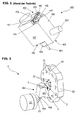
- the tool holder 100 consists of a substantially rectangular Body 105, on the underside 103 in a recessed portion 104 a tensioning device 108 for receiving a tool 109, for example a drill or milling cutter attached is.
- a tensioning device 108 for receiving a tool 109, for example a drill or milling cutter attached is.
- a bolt 107 with Locking device for fixing the tool holder 100 in one of the bores 51, the in Are arranged near the circumference of the turret disk 50 of a turret, is plugged and there snaps into place (see Figure 2).
- an adjusting device 110 is on the rear side 106 arranged, which serves the tool 109 exactly on the workpiece to be machined 53, which is clamped in a workpiece holder 55, for example a rotary spindle (see FIG. 2).
- the adjusting device 110 consists of a base surface 111 of the two mutually spaced Justierblöcke 112, 113 protrude vertically.
- In the base area 111 are two bores 116, with two threaded holes in the tool holder body 105 are aligned and over which the adjusting device 110 by two screws with the Tool holder 100 is connected.
- Adjustment pins 52 in the gap 117 between the two Justierblöcken 112, 113.
- Each of the two adjusting blocks 112, 113 has a transverse bore 114, 115 with Internal thread through which protrude the adjusting screws into the gap 117.
- the two adjustment screws are up bolted to the stop against the adjusting pin 52 in the intermediate space 117, wherein Turning the adjusting screws in a different depth causes a rotation of the whole Tool holder 100 with the tool 109 about serving as a rotation axis pin 107th he follows.
- the present invention is therefore the object of an adjusting device a tool holder of a CNC lathe in such a way that the alignment the tool holder and in particular very subtle changes for the operator easier and with less time to perform.
- the rotatably mounted in a longitudinal bore of the adjusting device according to the invention Bush has an eccentric bore, in which during assembly of the tool holder on the turret engages an adjusting pin of the revolver disc.
- a lug surface In the Starting surface may be, for example, a mandrel permanently connected to the bushing act, which protrudes from the socket and is easy to grip for the operator.
- a recess for engaging a Auxiliary tool for example a hexagonal recess for an Allen wrench, intended.
- the operator allows the operator to fix the adjusted adjustment, that is the position of the socket. So can For example, performed with a first tool holder, a first processing step Then, this first tool holder will be loosened from the turret disk with a second tool holder a second, other processing step or the Machining another workpiece and then with the first Tool holder to repeat the first machining, without the tool holder again to adjust.
- This fixation is via a transverse bore, which is in the longitudinal bore for receiving the socket opens and a fixing pin, which up to the stop in the socket in the transverse bore is inserted and the bush is fixed in this way.
- the transverse bore an internal thread and the fixing pin is in the form of a clamping screw.
- a spring arranged, which biases the sleeve in the direction of the turret plate. This is the result Adjusting pin always completely absorbed in the bore of the socket and a secure Guaranteed connection between the adjusting pin and the socket.
- the adjustment device is not as a separate Component executed, but integrated into the body of the tool holder.
- the toolholder body itself here has a longitudinal bore for rotatably receiving the socket with a eccentric bore on.
- This embodiment reduces the number of components and simplifies the manufacture of the adjusting device. Is the socket in the body of the Tool holder installed, that a rotation of the socket over a shoulder surface on the of the turret disc side facing away from the socket is not possible, this can be done by means of an actuator and adjusting means take place:
- an actuator for example, a thumbwheel serve, which is mostly located in a recess of the tool holder body, wherein only a narrow edge segment of the setting wheel the surface of the tool holder body surmounted.
- the thumbwheel and the socket each have on their surface teeth, the mesh with each other.
- the operator turns with their Fingers the thumbwheel, causing the rotary motion directly over the meshing teeth on the Socket is transmitted and an adjustment of the instrument as described above. is the distance between the actuator and the socket too large for a direct contact, so the forwarding of the rotational movement takes place via adjusting means, preferably shafts and / or Gears that establish an operative connection between the actuator and the socket.
- adjusting means preferably shafts and / or Gears that establish an operative connection between the actuator and the socket.
- a separate adjusting device with an actuator and Adjusting means be equipped to align the tool on the workpiece for the Operator even more comfortable.
- the tool holder with the adjusting pins of the turret for the operator to facilitate, in one embodiment, the free, from the end face of the Revolver disc pioneering ends of the alignment pins and that of the turret disk technological end of the eccentric bore or the entire bore conically shaped.
- FIG 2 is a coupling device 1 for releasably connecting a Tool holder 100 with the turret of a CNC lathe, with a rotatable mounted turret disk 50, at the plurality of radially from the end face 54 of the Turret disk 50 protruding alignment pins 52 are arranged, and a tool holder 100 with a bolt 107 (see Figure 1) for fixing the tool holder 100 in one of Holes 51 in the vicinity of the circumference of the turret disk 50 and with an inventive Adjusting device 2 for aligning the tool 109 shown on the workpiece 53.
- the Adjustment takes place by turning a cylindrical bushing 3, which in a longitudinal bore. 4 the adjusting device 2 is rotatably mounted.
- the adjusting device 2 is shown enlarged in FIG. Of the for better clarity, the bush 3 is shown outside the longitudinal bore 4, whereby a shoulder 7 is visible which is at that end of the longitudinal bore 4 which, when the tool holder 100 is attached to the turret plate 50, the end face 54 of Turret plate 50 faces.
- the shoulder 7 serves to support the bushing 3 and prevents slipping out of the bushing 3 from the longitudinal bore 4.
- a stepped Attachment 9 of the adjusting device 2 is a transverse bore 8 with internal thread arranged in the longitudinal bore 4 opens.
- the transverse bore 8 receives a clamping screw, which up on Stop is screwed to the socket 3 in the transverse bore 8 and the socket 3 in their position and thus the adjustment of the tool 109 fixed.
- the holes 10 and 11 are used to attach the adjusting device 2 on the body 105 of the tool holder 100 by means of screws whose length is selected so that they through the Adjustment device 2 through in, to the holes 10, 11 subsequent, Inside tapped holes of the tool holder body 105 protrude. Hole 12 creates space for Receiving a further adjusting pin 52, which in attachment of the tool holder 100 to the Revolver disk 50 is covered by the adjusting device 2, for the adjustment process but does not matter.
- a shoulder surface 6 in the form of a depression with a To recognize hexagonal edge 13, for engagement of an auxiliary tool, for example a Allen wrench, which facilitates the rotation of the socket 3 by the operator.
- an auxiliary tool for example a Allen wrench
- At the approach surface 6 includes the eccentric bore 5 for receiving a Justierlixs 52.
- FIG. 3 shows a tool holder 100, in which the clamping device 108 is opposite the tool holder body 105 is pivotable.
- the adjusting device 2 according to the invention is is arranged in a rectangular attachment 14, the smallest with its surface Tool holder body 105 is placed and screwed with this.
- the essay 14 covers This embodiment no further adjustment pin 52 from, as in the Adjusting device 52 in Figure 2 is the case, whereby an additional bore 12 (see Figure 4) is not necessary.
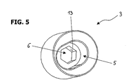
- FIG. 5 shows the bush 3 from that side which, when the tool holder 100 is attached to the Turret plate 50 is fixed, the end face 54 of the turret plate 50 faces. you recognizes that the eccentric bore 5 for receiving a Justierstatts 52 as a slot is formed to compensate for the length during the adjustment process of the stationary To ensure alignment pin with respect to the moving socket 3. Close to the hole 5 the approach surface 6 in the form of a recess with a hexagonal edge 13 at.
- the invention is not limited to the described embodiment, but includes all possible embodiments, the principle of principle, analogous operation of the Do not change the invention.
- the invention is independent of various types of revolver heads and revolver discs and can, for example, to star turrets be implemented.
Landscapes
- Engineering & Computer Science (AREA)
- Mechanical Engineering (AREA)
- Cutting Tools, Boring Holders, And Turrets (AREA)
Applications Claiming Priority (2)
| Application Number | Priority Date | Filing Date | Title |
|---|---|---|---|
| AT15842003A AT500168B1 (de) | 2003-10-08 | 2003-10-08 | Justiervorrichtung für einen werkzeughalter einer cnc - drehmaschine |
| AT15842003 | 2003-10-08 |
Publications (1)
| Publication Number | Publication Date |
|---|---|
| EP1522360A1 true EP1522360A1 (fr) | 2005-04-13 |
Family
ID=34280369
Family Applications (1)
| Application Number | Title | Priority Date | Filing Date |
|---|---|---|---|
| EP04023750A Withdrawn EP1522360A1 (fr) | 2003-10-08 | 2004-10-06 | Dispositif de réglage d'un porte-outil d'un tour à commande numérique |
Country Status (2)
| Country | Link |
|---|---|
| EP (1) | EP1522360A1 (fr) |
| AT (1) | AT500168B1 (fr) |
Cited By (3)
| Publication number | Priority date | Publication date | Assignee | Title |
|---|---|---|---|---|
| WO2011151058A1 (fr) * | 2010-06-02 | 2011-12-08 | Sauter Feinmechanik Gmbh | Dispositif d'ajustement |
| CN108339991A (zh) * | 2018-05-14 | 2018-07-31 | 河南理工大学 | 一种车床用车刀调整装置 |
| IT201700068900A1 (it) * | 2017-06-21 | 2018-12-21 | Algra S P A | Dispositivo per il posizionamento angolare preciso di porta-utensili utilizzabili su macchine a controllo numerico e porta-utensili provvisto di tale dispositivo |
Citations (4)
| Publication number | Priority date | Publication date | Assignee | Title |
|---|---|---|---|---|
| DE4102529A1 (de) * | 1991-01-29 | 1992-07-30 | Hans Kohn Fa | Werkzeughalterung |
| DE4139573A1 (de) * | 1991-11-30 | 1993-06-03 | Krupp Widia Gmbh | Justiervorrichtung |
| DE20009102U1 (de) * | 2000-05-20 | 2001-03-08 | Sauter Feinmechanik Gmbh, 72555 Metzingen | Ausrichteinrichtung |
| DE19940330A1 (de) * | 1999-08-25 | 2001-03-15 | Esa Eppinger Gmbh | Werkzeugspanneinrichtung |
Family Cites Families (3)
| Publication number | Priority date | Publication date | Assignee | Title |
|---|---|---|---|---|
| US3732760A (en) * | 1971-02-10 | 1973-05-15 | W Parks | Tool holder |
| GB2019292B (en) * | 1978-03-18 | 1982-08-04 | Herbert Ltd A | Tool carrier |
| WO1989003266A1 (fr) * | 1987-10-13 | 1989-04-20 | KROLL, Klaus-Dieter | Machine-outil, accessoire de serrage et tete d'outil |
-
2003
- 2003-10-08 AT AT15842003A patent/AT500168B1/de not_active IP Right Cessation
-
2004
- 2004-10-06 EP EP04023750A patent/EP1522360A1/fr not_active Withdrawn
Patent Citations (4)
| Publication number | Priority date | Publication date | Assignee | Title |
|---|---|---|---|---|
| DE4102529A1 (de) * | 1991-01-29 | 1992-07-30 | Hans Kohn Fa | Werkzeughalterung |
| DE4139573A1 (de) * | 1991-11-30 | 1993-06-03 | Krupp Widia Gmbh | Justiervorrichtung |
| DE19940330A1 (de) * | 1999-08-25 | 2001-03-15 | Esa Eppinger Gmbh | Werkzeugspanneinrichtung |
| DE20009102U1 (de) * | 2000-05-20 | 2001-03-08 | Sauter Feinmechanik Gmbh, 72555 Metzingen | Ausrichteinrichtung |
Cited By (4)
| Publication number | Priority date | Publication date | Assignee | Title |
|---|---|---|---|---|
| WO2011151058A1 (fr) * | 2010-06-02 | 2011-12-08 | Sauter Feinmechanik Gmbh | Dispositif d'ajustement |
| IT201700068900A1 (it) * | 2017-06-21 | 2018-12-21 | Algra S P A | Dispositivo per il posizionamento angolare preciso di porta-utensili utilizzabili su macchine a controllo numerico e porta-utensili provvisto di tale dispositivo |
| EP3417993A1 (fr) * | 2017-06-21 | 2018-12-26 | Algra S.P.A. | Dispositif de positionnement angulaire précis de porte-outils adaptés aux machines à commande numérique et porte-outils équipés d'un tel dispositif |
| CN108339991A (zh) * | 2018-05-14 | 2018-07-31 | 河南理工大学 | 一种车床用车刀调整装置 |
Also Published As
| Publication number | Publication date |
|---|---|
| AT500168A1 (de) | 2005-11-15 |
| AT500168B1 (de) | 2007-04-15 |
Similar Documents
| Publication | Publication Date | Title |
|---|---|---|
| DE69807182T2 (de) | Werkzeugkupplung und methode zum kupplung zweier werkzeugelementen | |
| DE4237422C2 (de) | Werkstückhaltevorrichtung für auf Werkzeugmaschinen mehrseitig zu bearbeitende Werkstücke | |
| EP1140400B1 (fr) | Outil a enlevement de copeaux pour usinage a vitesse elevee | |
| DE9313602U1 (de) | Zweifach-Werkzeugträger für Handbohrmaschinen | |
| EP0182290A2 (fr) | Tête de fraisage | |
| EP0416610B1 (fr) | Porte-outil, notamment pour tours, avec porte-outil interchangeable | |
| DE69512931T2 (de) | Fräser für zwei drehrichtungen mit indexierbaren spannteilen und schneideinsätze | |
| EP0296460A1 (fr) | Outil pour l'usinage circonferentiel de pièces, en particulier pour le forage | |
| DE4021090C2 (de) | Bearbeitungsvorrichtung mit Mitteln zur Änderung der radialen Position von Schneidwerkzeugen | |
| EP1878534B1 (fr) | Dispositif pour orienter une broche porte-outil comprenant une charnière | |
| EP0962280B1 (fr) | Dispositif d'alignement | |
| DE10151528A1 (de) | Senkrechtdrehmaschine mit einem Vorsatzkopf an einem Werkzeugschieber | |
| EP2114601B1 (fr) | Porte-outil | |
| WO1987004959A1 (fr) | Porte-outil ajustable de fraisage de rainures pour machines-outils | |
| EP0416611B1 (fr) | Installation d'un porte-outil interchangeable sur la tourelle revolver d'un tour | |
| DE8422976U1 (de) | Werkzeughalter mit Radialverstellvorrichtung für ein Werkzeug, insbesondere ein rotierendes Werkzeug | |
| EP0129116B1 (fr) | Outil à fraiser vers l'avant et vers l'arrière | |
| AT500168B1 (de) | Justiervorrichtung für einen werkzeughalter einer cnc - drehmaschine | |
| DE3909643C2 (de) | Mehrschneidenwerkzeugkopf zur spanabhebenden Vor- und Feinbearbeitung mit kreisförmiger Schnittbewegung | |
| DE102020123783B4 (de) | Vorrichtung zum zerspanenden Bearbeiten | |
| DE3242765A1 (de) | Planfraeskopf mit einstellbarer planschlichtschneide | |
| DE8401019U1 (de) | Bohr- und Ausdrehwerkzeug | |
| DE19947946B4 (de) | Fräser zur Bearbeitung von insbesondere transparenten Kunststoffmaterialien | |
| DE3026513A1 (de) | Aufbohrwerkzeug, insbes. plansenker | |
| DE102019002729B4 (de) | Vorrichtung zur Finishbearbeitung von Werkstückoberflächen |
Legal Events
| Date | Code | Title | Description |
|---|---|---|---|
| PUAI | Public reference made under article 153(3) epc to a published international application that has entered the european phase |
Free format text: ORIGINAL CODE: 0009012 |
|
| AK | Designated contracting states |
Kind code of ref document: A1 Designated state(s): AT BE BG CH CY CZ DE DK EE ES FI FR GB GR HU IE IT LI LU MC NL PL PT RO SE SI SK TR |
|
| AX | Request for extension of the european patent |
Extension state: AL HR LT LV MK |
|
| AKX | Designation fees paid | ||
| REG | Reference to a national code |
Ref country code: DE Ref legal event code: 8566 |
|
| STAA | Information on the status of an ep patent application or granted ep patent |
Free format text: STATUS: THE APPLICATION IS DEEMED TO BE WITHDRAWN |
|
| 18D | Application deemed to be withdrawn |
Effective date: 20051014 |