EP1522360A1 - Adjusting device for a tool holder of a CNC - turning lathe - Google Patents
Adjusting device for a tool holder of a CNC - turning lathe Download PDFInfo
- Publication number
- EP1522360A1 EP1522360A1 EP04023750A EP04023750A EP1522360A1 EP 1522360 A1 EP1522360 A1 EP 1522360A1 EP 04023750 A EP04023750 A EP 04023750A EP 04023750 A EP04023750 A EP 04023750A EP 1522360 A1 EP1522360 A1 EP 1522360A1
- Authority
- EP
- European Patent Office
- Prior art keywords
- tool holder
- adjusting device
- bore
- bushing
- tool
- Prior art date
- Legal status (The legal status is an assumption and is not a legal conclusion. Google has not performed a legal analysis and makes no representation as to the accuracy of the status listed.)
- Withdrawn
Links
Images

Classifications
-
- B—PERFORMING OPERATIONS; TRANSPORTING
- B23—MACHINE TOOLS; METAL-WORKING NOT OTHERWISE PROVIDED FOR
- B23B—TURNING; BORING
- B23B29/00—Holders for non-rotary cutting tools; Boring bars or boring heads; Accessories for tool holders
- B23B29/04—Tool holders for a single cutting tool
- B23B29/12—Special arrangements on tool holders
- B23B29/20—Special arrangements on tool holders for placing same by shanks in sleeves of a turret
- B23B29/205—Special arrangements on tool holders for placing same by shanks in sleeves of a turret the tools being adjustable
-
- B—PERFORMING OPERATIONS; TRANSPORTING
- B23—MACHINE TOOLS; METAL-WORKING NOT OTHERWISE PROVIDED FOR
- B23Q—DETAILS, COMPONENTS, OR ACCESSORIES FOR MACHINE TOOLS, e.g. ARRANGEMENTS FOR COPYING OR CONTROLLING; MACHINE TOOLS IN GENERAL CHARACTERISED BY THE CONSTRUCTION OF PARTICULAR DETAILS OR COMPONENTS; COMBINATIONS OR ASSOCIATIONS OF METAL-WORKING MACHINES, NOT DIRECTED TO A PARTICULAR RESULT
- B23Q3/00—Devices holding, supporting, or positioning work or tools, of a kind normally removable from the machine
- B23Q3/18—Devices holding, supporting, or positioning work or tools, of a kind normally removable from the machine for positioning only
-
- B—PERFORMING OPERATIONS; TRANSPORTING
- B23—MACHINE TOOLS; METAL-WORKING NOT OTHERWISE PROVIDED FOR
- B23B—TURNING; BORING
- B23B2265/00—Details of general geometric configurations
- B23B2265/12—Eccentric
Definitions
- the present invention relates to an adjusting device for a tool holder of a CNC lathe for exact alignment of the clamped in the toolholder Tool on the workpiece to be machined.
- the tool holder 100 consists of a substantially rectangular Body 105, on the underside 103 in a recessed portion 104 a tensioning device 108 for receiving a tool 109, for example a drill or milling cutter attached is.
- a tensioning device 108 for receiving a tool 109, for example a drill or milling cutter attached is.
- a bolt 107 with Locking device for fixing the tool holder 100 in one of the bores 51, the in Are arranged near the circumference of the turret disk 50 of a turret, is plugged and there snaps into place (see Figure 2).
- an adjusting device 110 is on the rear side 106 arranged, which serves the tool 109 exactly on the workpiece to be machined 53, which is clamped in a workpiece holder 55, for example a rotary spindle (see FIG. 2).
- the adjusting device 110 consists of a base surface 111 of the two mutually spaced Justierblöcke 112, 113 protrude vertically.
- In the base area 111 are two bores 116, with two threaded holes in the tool holder body 105 are aligned and over which the adjusting device 110 by two screws with the Tool holder 100 is connected.
- Adjustment pins 52 in the gap 117 between the two Justierblöcken 112, 113.
- Each of the two adjusting blocks 112, 113 has a transverse bore 114, 115 with Internal thread through which protrude the adjusting screws into the gap 117.
- the two adjustment screws are up bolted to the stop against the adjusting pin 52 in the intermediate space 117, wherein Turning the adjusting screws in a different depth causes a rotation of the whole Tool holder 100 with the tool 109 about serving as a rotation axis pin 107th he follows.
- the present invention is therefore the object of an adjusting device a tool holder of a CNC lathe in such a way that the alignment the tool holder and in particular very subtle changes for the operator easier and with less time to perform.
- the rotatably mounted in a longitudinal bore of the adjusting device according to the invention Bush has an eccentric bore, in which during assembly of the tool holder on the turret engages an adjusting pin of the revolver disc.
- a lug surface In the Starting surface may be, for example, a mandrel permanently connected to the bushing act, which protrudes from the socket and is easy to grip for the operator.
- a recess for engaging a Auxiliary tool for example a hexagonal recess for an Allen wrench, intended.
- the operator allows the operator to fix the adjusted adjustment, that is the position of the socket. So can For example, performed with a first tool holder, a first processing step Then, this first tool holder will be loosened from the turret disk with a second tool holder a second, other processing step or the Machining another workpiece and then with the first Tool holder to repeat the first machining, without the tool holder again to adjust.
- This fixation is via a transverse bore, which is in the longitudinal bore for receiving the socket opens and a fixing pin, which up to the stop in the socket in the transverse bore is inserted and the bush is fixed in this way.
- the transverse bore an internal thread and the fixing pin is in the form of a clamping screw.
- a spring arranged, which biases the sleeve in the direction of the turret plate. This is the result Adjusting pin always completely absorbed in the bore of the socket and a secure Guaranteed connection between the adjusting pin and the socket.
- the adjustment device is not as a separate Component executed, but integrated into the body of the tool holder.
- the toolholder body itself here has a longitudinal bore for rotatably receiving the socket with a eccentric bore on.
- This embodiment reduces the number of components and simplifies the manufacture of the adjusting device. Is the socket in the body of the Tool holder installed, that a rotation of the socket over a shoulder surface on the of the turret disc side facing away from the socket is not possible, this can be done by means of an actuator and adjusting means take place:
- an actuator for example, a thumbwheel serve, which is mostly located in a recess of the tool holder body, wherein only a narrow edge segment of the setting wheel the surface of the tool holder body surmounted.
- the thumbwheel and the socket each have on their surface teeth, the mesh with each other.
- the operator turns with their Fingers the thumbwheel, causing the rotary motion directly over the meshing teeth on the Socket is transmitted and an adjustment of the instrument as described above. is the distance between the actuator and the socket too large for a direct contact, so the forwarding of the rotational movement takes place via adjusting means, preferably shafts and / or Gears that establish an operative connection between the actuator and the socket.
- adjusting means preferably shafts and / or Gears that establish an operative connection between the actuator and the socket.
- a separate adjusting device with an actuator and Adjusting means be equipped to align the tool on the workpiece for the Operator even more comfortable.
- the tool holder with the adjusting pins of the turret for the operator to facilitate, in one embodiment, the free, from the end face of the Revolver disc pioneering ends of the alignment pins and that of the turret disk technological end of the eccentric bore or the entire bore conically shaped.
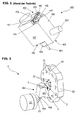
- FIG 2 is a coupling device 1 for releasably connecting a Tool holder 100 with the turret of a CNC lathe, with a rotatable mounted turret disk 50, at the plurality of radially from the end face 54 of the Turret disk 50 protruding alignment pins 52 are arranged, and a tool holder 100 with a bolt 107 (see Figure 1) for fixing the tool holder 100 in one of Holes 51 in the vicinity of the circumference of the turret disk 50 and with an inventive Adjusting device 2 for aligning the tool 109 shown on the workpiece 53.
- the Adjustment takes place by turning a cylindrical bushing 3, which in a longitudinal bore. 4 the adjusting device 2 is rotatably mounted.
- the adjusting device 2 is shown enlarged in FIG. Of the for better clarity, the bush 3 is shown outside the longitudinal bore 4, whereby a shoulder 7 is visible which is at that end of the longitudinal bore 4 which, when the tool holder 100 is attached to the turret plate 50, the end face 54 of Turret plate 50 faces.
- the shoulder 7 serves to support the bushing 3 and prevents slipping out of the bushing 3 from the longitudinal bore 4.
- a stepped Attachment 9 of the adjusting device 2 is a transverse bore 8 with internal thread arranged in the longitudinal bore 4 opens.
- the transverse bore 8 receives a clamping screw, which up on Stop is screwed to the socket 3 in the transverse bore 8 and the socket 3 in their position and thus the adjustment of the tool 109 fixed.
- the holes 10 and 11 are used to attach the adjusting device 2 on the body 105 of the tool holder 100 by means of screws whose length is selected so that they through the Adjustment device 2 through in, to the holes 10, 11 subsequent, Inside tapped holes of the tool holder body 105 protrude. Hole 12 creates space for Receiving a further adjusting pin 52, which in attachment of the tool holder 100 to the Revolver disk 50 is covered by the adjusting device 2, for the adjustment process but does not matter.
- a shoulder surface 6 in the form of a depression with a To recognize hexagonal edge 13, for engagement of an auxiliary tool, for example a Allen wrench, which facilitates the rotation of the socket 3 by the operator.
- an auxiliary tool for example a Allen wrench
- At the approach surface 6 includes the eccentric bore 5 for receiving a Justierlixs 52.
- FIG. 3 shows a tool holder 100, in which the clamping device 108 is opposite the tool holder body 105 is pivotable.
- the adjusting device 2 according to the invention is is arranged in a rectangular attachment 14, the smallest with its surface Tool holder body 105 is placed and screwed with this.
- the essay 14 covers This embodiment no further adjustment pin 52 from, as in the Adjusting device 52 in Figure 2 is the case, whereby an additional bore 12 (see Figure 4) is not necessary.
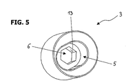
- FIG. 5 shows the bush 3 from that side which, when the tool holder 100 is attached to the Turret plate 50 is fixed, the end face 54 of the turret plate 50 faces. you recognizes that the eccentric bore 5 for receiving a Justierstatts 52 as a slot is formed to compensate for the length during the adjustment process of the stationary To ensure alignment pin with respect to the moving socket 3. Close to the hole 5 the approach surface 6 in the form of a recess with a hexagonal edge 13 at.
- the invention is not limited to the described embodiment, but includes all possible embodiments, the principle of principle, analogous operation of the Do not change the invention.
- the invention is independent of various types of revolver heads and revolver discs and can, for example, to star turrets be implemented.
Abstract
Description
Die vorliegende Erfindung betrifft eine Justiervorrichtung für einen Werkzeughalter einer CNC - Drehmaschine zur exakten Ausrichtung des im Werkzeughalter eingespannten Werkzeugs auf das zu bearbeitende Werkstück.The present invention relates to an adjusting device for a tool holder of a CNC lathe for exact alignment of the clamped in the toolholder Tool on the workpiece to be machined.
Ein Werkzeughalter mit einer derartigen Justiervorrichtung ist in Figur 1 (Stand der
Technik) dargestellt. Der Werkzeughalter 100 besteht aus einem im wesentlichen rechteckigen
Körper 105, an dessen Unterseite 103 in einem vertieften Abschnitt 104 eine Spannvorrichtung
108 zur Aufnahme eines Werkzeugs 109, zum Beispiel eines Bohrers oder Fräsers, angebracht
ist. An der Rückseite 106 des Werkzeughalter-Körpers 105 befindet sich ein Bolzen 107 mit
Rastvorrichtung, der zur Fixierung des Werkzeughalters 100 in einer der Bohrungen 51, die in
Umfangsnähe der Revolverscheibe 50 eines Revolverkopfs angeordneten sind, gesteckt wird
und dort einrastet (siehe Figur 2). Weiters ist an der Rückseite 106 eine Justiervorrichtung 110
angeordnet, die dazu dient, das Werkzeug 109 exakt auf das zu bearbeitende Werkstück 53,
das in einer Werkstückaufnahme 55, zum Beispiel einer Drehspindel, eingespannt ist (siehe
Figur 2), auszurichten. Die Justiervorrichtung 110 besteht aus einer Basisfläche 111 von der
zwei voneinander beabstandete Justierblöcke 112, 113 senkrecht abstehen. In der Basisfläche
111 befinden sich zwei Bohrungen 116, die mit zwei Gewindebohrungen im Werkzeughalter-Körper
105 fluchten und über die die Justiervorrichtung 110 durch zwei Schrauben mit dem
Werkzeughalter 100 verbunden ist. Wird der Werkzeughalter 100 an der Revolverscheibe 50
befestigt, so ragt einer der radial von der Stirnfläche 54 der Revolverscheibe 50 abstehenden
Justierstifte 52 (siehe Figur 2) in den Zwischenraum 117 zwischen den beiden Justierblöcken
112, 113. Jeder der beiden Justierblöcke 112, 113 weist eine Querbohrung 114, 115 mit
Innengewinde auf, durch die die Justierschrauben in den Zwischenraum 117 ragen. Zur
Ausrichtung des Werkzeugs 109 auf das Werkstück 53 werden die beiden Justierschrauben bis
zum Anschlag gegen den Justierstift 52 in den Zwischenraum 117 geschraubt, wobei durch
unterschiedlich tiefes Eindrehen der Justierschrauben eine Drehung des gesamten
Werkzeughalters 100 mit dem Werkzeug 109 um den als Drehachse dienenden Bolzen 107
erfolgt.A tool holder with such an adjusting device is shown in FIG
Technology). The
Nachteilig bei dieser Justiervorrichtung ist, daß die Justierschrauben bei an der Revolverscheibe fixiertem Werkzeughalter schwer zugänglich sind, wodurch eine exakte Justierung für den Bediener der Maschine sehr umständlich und zeitaufwendig ist. Es sei darauf verwiesen, daß insbesondere bei der bohrenden Bearbeitung kleiner Werkstücke äußerste Genauigkeit bei der Justierung notwendig ist, mit Abweichungen von weniger als 0,01 mm auf einer Länge von 30 mm. Die Bedienungsperson steht seitlich neben der CNC - Drehmaschine, so daß sie in etwa mit einem Blickwinkel wie er in Figur 2 dargestellt ist auf die Justiervorrichtung sieht. Die von der Bedienungsperson weiter entfernte, hintere Justierschraube ist daher nicht einzusehen und aufgrund der beengten Platzverhältnisse sind feine Veränderungen an der Schraube sehr schwer durchzuführen.The disadvantage of this adjusting device is that the adjusting screws in at the Turret disk fixed tool holder are difficult to access, creating an exact Adjustment for the operator of the machine is very cumbersome and time consuming. It is important pointed out that especially in the drilling of small workpieces utmost Accuracy in the adjustment is necessary, with deviations of less than 0.01 mm a length of 30 mm. The operator stands sideways beside the CNC lathe, so that it is approximately at an angle as shown in Figure 2 on the Adjustment device sees. The far away from the operator, the rear Adjustment screw is therefore not visible and are due to the limited space fine changes to the screw very difficult to perform.
Der vorliegenden Erfindung liegt daher die Aufgabe zugrunde eine Justiervorrichtung eines Werkzeughalters einer CNC - Drehmaschine derart weiterzubilden, daß die Ausrichtung des Werkzeughalters und insbesondere sehr feine Veränderungen für die Bedienungsperson einfacher und mit weniger zeitlichem Aufwand durchzuführen sind.The present invention is therefore the object of an adjusting device a tool holder of a CNC lathe in such a way that the alignment the tool holder and in particular very subtle changes for the operator easier and with less time to perform.
Diese Aufgabe wird gemäß der vorliegenden Erfindung durch eine Justiervorrichtung mit
den Merkmalen des Anspruchs 1, einen Werkzeughalter gemäß Anspruch 7 bzw. einer
Kupplungsvorrichtung gemäß Anspruch 9 gelöst.This object is achieved according to the present invention by an adjusting device
the features of claim 1, a tool holder according to
Die in einer Längsbohrung der erfindungsgemäßen Justiervorrichtung drehbar gelagerte Buchse weist eine exzentrische Bohrung auf, in welche bei der Montage des Werkzeughalters an den Revolverkopf ein Justierstift der Revolverscheibe eingreift. Durch Verdrehen der Buchse durch die Bedienungsperson folgt der Werkzeughalter mit dem eingespannten Instrument der Kreisbahn der Buchse, wodurch eine unkomplizierte Justierung des Instruments in Bezug auf das Werkstück möglich wird.The rotatably mounted in a longitudinal bore of the adjusting device according to the invention Bush has an eccentric bore, in which during assembly of the tool holder on the turret engages an adjusting pin of the revolver disc. By turning the socket by the operator follows the tool holder with the clamped instrument of Circular path of the socket, allowing a straightforward adjustment of the instrument with respect to the workpiece becomes possible.
Um der Bedienungsperson das Verdrehen zu vereinfachen ist an der von der Revolverscheibe abgewandten Seite der Buchse eine Ansatzfläche angeordnet. Bei der Ansatzfläche kann es sich beispielsweise um einen unlösbar mit der Buchse verbundenen Dorn handeln, der von der Buchse absteht und für die Bedienungsperson einfach zu greifen ist. Aus Gründen der Platzersparnis ist als Ansatzfläche bevorzugt eine Vertiefung zum Eingriff eines Hilfswerkzeugs, zum Beispiel eine sechskantige Vertiefung für einen Inbusschlüssel, vorgesehen.To simplify the twisting of the operator is at the of the Revolver disc opposite side of the socket arranged a lug surface. In the Starting surface may be, for example, a mandrel permanently connected to the bushing act, which protrudes from the socket and is easy to grip for the operator. Out To save space is preferred as an approach surface a recess for engaging a Auxiliary tool, for example a hexagonal recess for an Allen wrench, intended.
In einem bevorzugten Ausführungsbeispiel soll es der Bedienungsperson ermöglicht werden, die eingestellte Justierung, das heißt die Stellung der Buchse, zu fixieren. So kann beispielsweise mit einem ersten Werkzeughalter ein erster Bearbeitungsschritt durchgeführt werden, dieser erste Werkzeughalter anschließend von der Revolverscheibe gelöst werden um mit einem zweiten Werkzeughalter einen zweiten, anderen Bearbeitungsschritt oder die Bearbeitung eines anderen Werkstücks durchzuführen und anschließend mit dem ersten Werkzeughalter die erste Bearbeitung zu wiederholen, ohne dafür den Werkzeughalter wieder justieren zu müssen. Diese Fixierung erfolgt über eine Querbohrung, die in die Längsbohrung zur Aufnahme der Buchse mündet und einen Fixierstift, der bis auf Anschlag an die Buchse in die Querbohrung eingeführt wird und die Buchse so fixiert. Bevorzugt weist die Querbohrung ein Innengewinde auf und ist der Fixierstift in Form einer Klemmschraube ausgebildet.In a preferred embodiment, it allows the operator to fix the adjusted adjustment, that is the position of the socket. So can For example, performed with a first tool holder, a first processing step Then, this first tool holder will be loosened from the turret disk with a second tool holder a second, other processing step or the Machining another workpiece and then with the first Tool holder to repeat the first machining, without the tool holder again to adjust. This fixation is via a transverse bore, which is in the longitudinal bore for receiving the socket opens and a fixing pin, which up to the stop in the socket in the transverse bore is inserted and the bush is fixed in this way. Preferably, the transverse bore an internal thread and the fixing pin is in the form of a clamping screw.
Zur Verringerung der benötigten Fertigungsgenauigkeit der Buchse bzw. der Längsbohrung ist in einem weiteren Ausführungsbeispiel in der Längsbohrung eine Feder angeordnet, die die Buchse in Richtung der Revolverscheibe vorspannt. Dadurch ist der Justierstift immer vollständig in der Bohrung der Buchse aufgenommen und eine sichere Verbindung zwischen dem Justierstift und der Buchse garantiert.To reduce the required manufacturing accuracy of the socket or the Longitudinal bore is in a further embodiment in the longitudinal bore a spring arranged, which biases the sleeve in the direction of the turret plate. This is the result Adjusting pin always completely absorbed in the bore of the socket and a secure Guaranteed connection between the adjusting pin and the socket.
In einem weiteren Ausführungsbeispiel ist die Justiervorrichtung nicht als separater Bauteil ausgeführt, sondern in den Körper des Werkzeughalters integriert. Der Werkzeughalter-Körper selbst weist hierbei eine Längsbohrung zur drehbaren Aufnahme der Buchse mit einer exzentrischen Bohrung auf. Diese Ausgestaltung reduziert die Anzahl der Bauteile und vereinfacht die Herstellung der Justiervorrichtung. Ist die Buchse derart in den Körper des Werkzeughalters eingebaut, daß ein Verdrehen der Buchse über eine Ansatzfläche an der von der Revolverscheibe abgewandten Seite der Buchse nicht möglich ist, so kann dies mittels eines Stellorgans und Stellmitteln erfolgen: Als Stellorgan kann beispielsweise ein Stellrad dienen, das größtenteils in einer Vertiefung des Werkzeughalter-Körpers angeordnet ist, wobei nur ein schmales Randsegment des Stellrads die Oberfläche des Werkzeughalter-Körpers überragt. Das Stellrad sowie die Buchse weisen jeweils an ihrer Oberfläche Zähne auf, die ineinander kämmen. Zur Justierung des Werkzeughalters dreht die Bedienungsperson mit ihren Fingern das Stellrad, wodurch die Drehbewegung direkt über die kämmenden Zähne auf die Buchse übertragen wird und eine Justierung des Instruments wie oben beschrieben erfolgt. Ist die Entfernung zwischen dem Stellorgan und der Buchse zu groß für einen direkten Kontakt, so erfolgt die Weiterleitung der Drehbewegung über Stellmittel, bevorzugt Wellen und / oder Zahnräder, die eine Wirkverbindung zwischen dem Stellorgan und der Buchse herstellen. Selbstverständlich kann auch eine separate Justiervorrichtung mit einem Stellorgan und Stellmitteln ausgestattet sein, um das Ausrichten des Werkzeugs auf das Werkstück für die Bedienungsperson noch komfortabler zu gestalten.In a further embodiment, the adjustment device is not as a separate Component executed, but integrated into the body of the tool holder. The toolholder body itself here has a longitudinal bore for rotatably receiving the socket with a eccentric bore on. This embodiment reduces the number of components and simplifies the manufacture of the adjusting device. Is the socket in the body of the Tool holder installed, that a rotation of the socket over a shoulder surface on the of the turret disc side facing away from the socket is not possible, this can be done by means of an actuator and adjusting means take place: As an actuator, for example, a thumbwheel serve, which is mostly located in a recess of the tool holder body, wherein only a narrow edge segment of the setting wheel the surface of the tool holder body surmounted. The thumbwheel and the socket each have on their surface teeth, the mesh with each other. To adjust the tool holder, the operator turns with their Fingers the thumbwheel, causing the rotary motion directly over the meshing teeth on the Socket is transmitted and an adjustment of the instrument as described above. is the distance between the actuator and the socket too large for a direct contact, so the forwarding of the rotational movement takes place via adjusting means, preferably shafts and / or Gears that establish an operative connection between the actuator and the socket. Of course, a separate adjusting device with an actuator and Adjusting means be equipped to align the tool on the workpiece for the Operator even more comfortable.
Um die Handhabung der Kupplungsvorrichtung und insbesondere das Zusammenfügen des Werkzeughalters mit den Justierstiften der Revolverscheibe für die Bedienungsperson zu erleichtern, werden in einem Ausführungsbeispiel die freien, von der Stirnfläche der Revolverscheibe wegweisenden Enden der Justierstifte und das von der Revolverscheibe wegweisende Ende der exzentrischen Bohrung oder die gesamte Bohrung konisch geformt.To handle the coupling device and in particular the assembly the tool holder with the adjusting pins of the turret for the operator to facilitate, in one embodiment, the free, from the end face of the Revolver disc pioneering ends of the alignment pins and that of the turret disk groundbreaking end of the eccentric bore or the entire bore conically shaped.
Die Erfindung wird nachfolgend anhand eines bevorzugten Ausführungsbeispiels und Bezug nehmend auf die beigefügten Zeichnungen erläutert:
- Figur 1
- zeigt einen Werkzeughalter einer CNC - Drehmaschine mit einer Justiervorrichtung gemäß dem Stand der Technik.
Figur 2- zeigt eine Kupplungsvorrichtung einer CNC - Drehmaschine mit einer erfindungsgemäßen Justiervorrichtung.
Figur 3- zeigt die erfindungsgemäße Justiervorrichtung in einem schwenkbaren Werkzeughalter.
- Figur 4
- zeigt die erfindungsgemäße Justiervorrichtung.
Figur 5- zeigt eine Rückansicht der Buchse der erfindungsgemäßen Justiervorrichtung.
- FIG. 1
- shows a tool holder of a CNC lathe with an adjusting device according to the prior art.
- FIG. 2
- shows a coupling device of a CNC lathe with an adjusting device according to the invention.
- FIG. 3
- shows the adjusting device according to the invention in a pivotable tool holder.
- FIG. 4
- shows the adjusting device according to the invention.
- FIG. 5
- shows a rear view of the socket of the adjusting device according to the invention.
In Figur 2 ist eine Kupplungsvorrichtung 1 zur lösbaren Verbindung eines
Werkzeughalters 100 mit dem Revolverkopf einer CNC - Drehmaschine, mit einer drehbar
gelagerten Revolverscheibe 50, an der mehrere radial von der Stirnfläche 54 der
Revolverscheibe 50 abstehende Justierstifte 52 angeordnet sind, und einem Werkzeughalter
100 mit einem Bolzen 107 (siehe Figur 1) zur Fixierung des Werkzeughalters 100 in einer der
Bohrungen 51 in Umfangsnähe der Revolverscheibe 50 und mit einer erfindungsgemäßen
Justiervorrichtung 2 zur Ausrichtung des Werkzeugs 109 auf das Werkstück 53 dargestellt. Die
Justierung erfolgt durch Verdrehen einer zylindrischen Buchse 3, die in einer Längsbohrung 4
der Justiervorrichtung 2 drehbar gelagert ist.In Figure 2 is a coupling device 1 for releasably connecting a
Die erfindungsgemäße Justiervorrichtung 2 ist in Figur 4 vergrößert abgebildet. Der
besseren Übersichtlichkeit wegen ist die Buchse 3 außerhalb der Längsbohrung 4 dargestellt,
wodurch eine Schulter 7 sichtbar ist, die sich an jenem Ende der Längsbohrung 4 befindet, das,
wenn der Werkzeughalter 100 an der Revolverscheibe 50 befestigt ist, der Stirnfläche 54 der
Revolverscheibe 50 zugewandt ist. Die Schulter 7 dient der Lagerung der Buchse 3 und
verhindert ein Herausrutschen der Buchse 3 aus der Längsbohrung 4. In einem stufenförmigen
Aufsatz 9 der Justiervorrichtung 2 ist eine Querbohrung 8 mit Innengewinde angeordnet, die in
die Längsbohrung 4 mündet. Die Querbohrung 8 nimmt einer Klemmschraube auf, die bis auf
Anschlag an die Buchse 3 in die Querbohrung 8 eingeschraubt wird und die Buchse 3 so in
ihrer Position und somit die Justierung des Werkzeugs 109 fixiert. Dadurch kann der
Werkzeughalter 100 mit der Justiervorrichtung 2 von der Revolverscheibe 50 gelöst und später
daran wieder befestigt werden, ohne daß ein nochmaliger Justiervorgang durch die
Bedienungsperson vorgenommen werden muß.The adjusting
Die Bohrungen 10 und 11 dienen der Befestigung der Justiervorrichtung 2 am Körper
105 des Werkzeughalters 100 mittels Schrauben, deren Länge so gewählt ist, daß sie durch die
Justiervorrichtung 2 hindurch in, an die Bohrungen 10, 11 anschließende,
Innengewindebohrungen des Werkzeughalter-Körpers 105 ragen. Bohrung 12 schafft Raum zur
Aufnahme eines weiteren Justierstifts 52, der bei Befestigung des Werkzeughalters 100 an der
Revolverscheibe 50 durch die Justiervorrichtung 2 abgedeckt wird, für den Justiervorgang
selbst aber keine Rolle spielt.The
An der Buchse 3 ist eine Ansatzfläche 6 in Form einer Vertiefung mit einem
sechskantigen Rand 13 zu erkennen, zum Eingriff eines Hilfswerkzeugs, zum Beispiel eines
Inbusschlüssels, die das Verdrehen der Buchse 3 durch die Bedienungsperson erleichtert. An
die Ansatzfläche 6 schließt die exzentrische Bohrung 5 zur Aufnahme eines Justierstifts 52 an.At the
Figur 3 zeigt einen Werkzeughalter 100, bei dem die Spannvorrichtung 108 gegenüber
dem Werkzeughalter-Körper 105 schwenkbar ist. Die erfindungsgemäße Justiervorrichtung 2 ist
in einem quaderförmigen Aufsatz 14 angeordnet ist, der mit seiner kleinsten Fläche dem
Werkzeughalter-Körper 105 aufgesetzt und mit diesem verschraubt ist. Der Aufsatz 14 deckt bei
diesem Ausführungsbeispiel keinen weiteren Justierstift 52 ab, wie dies bei der
Justiervorrichtung 52 in Figur 2 der Fall ist, wodurch auch eine zusätzliche Bohrung 12 (siehe
Figur 4) nicht notwendig ist.FIG. 3 shows a
Figur 5 zeigt die Buchse 3 von jener Seite, die, wenn der Werkzeughalter 100 an der
Revolverscheibe 50 befestigt ist, der Stirnfläche 54 der Revolverscheibe 50 zugewandt ist. Man
erkennt, daß die exzentrische Bohrung 5 zur Aufnahme eines Justierstifts 52 als Langloch
ausgebildet ist, um während des Justiervorgangs einen Längenausgleich des stationären
Justierstifts in Bezug auf die bewegte Buchse 3 zu gewährleisten. An die Bohrung 5 schließt
sich die Ansatzfläche 6 in Form einer Vertiefung mit einem sechskantigen Rand 13 an.FIG. 5 shows the
Die Erfindung ist nicht auf das beschriebene Ausführungsbeispiel beschränkt, sondern umfaßt alle Ausführungsmöglichkeiten, die das prinzipielle, sinngemäßen Funktionsprinzip der Erfindung nicht verändern. Insbesondere ist die Erfindung unabhängig von verschiedenen Arten von Revolverköpfen und Revolverscheiben und kann zum Beispiel auch an Sternrevolvern implementiert werden.The invention is not limited to the described embodiment, but includes all possible embodiments, the principle of principle, analogous operation of the Do not change the invention. In particular, the invention is independent of various types of revolver heads and revolver discs and can, for example, to star turrets be implemented.
Claims (9)
gekennzeichnet durch
eine Längsbohrung (4) in der eine Buchse (3) drehbar gelagert ist, wobei die Buchse (3) eine exzentrischer Bohrung (5) zur Aufnahme eines Justierstifts (52) der Revolverscheibe (50) aufweist.Adjusting device (2) for a tool holder (100) of a CNC lathe for exact alignment of the tool (109) clamped in the tool holder (100) with the workpiece (53) to be machined,
marked by
a longitudinal bore (4) in which a bushing (3) is rotatably mounted, wherein the bushing (3) has an eccentric bore (5) for receiving a Justierstifts (52) of the turret disk (50).
dadurch gekennzeichnet, daß
die exzentrische Bohrung (5) als Langloch ausgebildet ist.Adjusting device (2) according to claim 1,
characterized in that
the eccentric bore (5) is designed as a slot.
dadurch gekennzeichnet, daß
die Buchse (3) an ihrer von der Revolverscheibe (50) abgewandten Seite eine Ansatzfläche (6) zum Drehen der Buchse (3), bevorzugt eine Vertiefung zum Eingriff eines Hilfswerkzeugs, besonders bevorzugt eine sechskantige Vertiefung (13) für einen Inbusschlüssel, aufweist.Adjusting device (2) according to one of the preceding claims,
characterized in that
the bushing (3) has on its side remote from the turret disk (50) a shoulder surface (6) for rotating the bushing (3), preferably a recess for engaging an auxiliary tool, particularly preferably a hexagonal recess (13) for an Allen wrench.
gekennzeichnet durch
eine Querbohrung (8) zur Aufnahme eines Fixierstifts, die in die Längsbohrung (4) mündet.Adjusting device (2) according to one of the preceding claims,
marked by
a transverse bore (8) for receiving a fixing pin, which opens into the longitudinal bore (4).
dadurch gekennzeichnet, daß
die Querbohrung (8) ein Innengewinde zur Aufnahme einer Klemmschraube aufweist.Adjusting device (2) according to claim 4,
characterized in that
the transverse bore (8) has an internal thread for receiving a clamping screw.
dadurch gekennzeichnet, daß
in der Längsbohrung (4) eine Feder angeordnet ist, die die Buchse (3) in Richtung der Revolverscheibe (50) vorspannt.Adjusting device (2) according to one of the preceding claims,
characterized in that
in the longitudinal bore (4), a spring is arranged, which biases the bushing (3) in the direction of the turret disk (50).
gekennzeichnet durch
eine Längsbohrung im Werkzeughalter-Körper in der eine Buchse (3) drehbar gelagert ist, wobei die Buchse (3) eine exzentrischer Bohrung (5) zur Aufnahme eines Justierstifts (52) der Revolverscheibe (50) aufweist.Tool holder (100) of a CNC lathe with a toolholder body (105),
marked by
a longitudinal bore in the tool holder body in which a bushing (3) is rotatably mounted, wherein the bushing (3) has an eccentric bore (5) for receiving a Justierstifts (52) of the turret disk (50).
gekennzeichnet durch
ein Stellorgan, bevorzugt ein Stellrad, an der Justiervorrichtung (2) oder am Werkzeughalter-Körper (105), das direkt oder indirekt über ein oder mehrere Stellmittel, bevorzugt Wellen und / oder Zahnräder, mit der Buchse (3) in Wirkverbindung steht.Adjusting device (2) according to one of claims 1, 2, 4 - 6 or tool holder (100) according to claim 7,
marked by
an actuator, preferably a thumbwheel, on the adjusting device (2) or on the tool holder body (105), which is directly or indirectly via one or more adjusting means, preferably shafts and / or gears, with the sleeve (3) in operative connection.
gekennzeichnet durch
eine Justiervorrichtung (2) und / oder einen Werkzeughalter (100) nach einem der vorhergehenden Ansprüche, wobei zumindest das von der Revolverscheibe (50) wegweisende Ende der exzentrischen Bohrung (5) oder die gesamte Bohrung (5) sowie die freien Enden der Justierstifte (52) konisch geformt sind.Coupling device (1) of a CNC lathe for releasably connecting a tool holder (100) to a turret disk (50) of a turret on which a plurality of adjusting pins (52) projecting radially from the end face (54) of the turret disk (50) are arranged Tool holder (100) having an adjusting device (2) for exact alignment of the tool (109) clamped in the tool holder (100),
marked by
An adjusting device (2) and / or a tool holder (100) according to any one of the preceding claims, wherein at least the end of the eccentric bore (5) facing away from the turret disc (50) or the entire bore (5) and the free ends of the alignment pins (5). 52) are conically shaped.
Applications Claiming Priority (2)
| Application Number | Priority Date | Filing Date | Title |
|---|---|---|---|
| AT15842003A AT500168B1 (en) | 2003-10-08 | 2003-10-08 | ADJUSTMENT DEVICE FOR A TOOL HOLDER OF A CNC TURNING MACHINE |
| AT15842003 | 2003-10-08 |
Publications (1)
| Publication Number | Publication Date |
|---|---|
| EP1522360A1 true EP1522360A1 (en) | 2005-04-13 |
Family
ID=34280369
Family Applications (1)
| Application Number | Title | Priority Date | Filing Date |
|---|---|---|---|
| EP04023750A Withdrawn EP1522360A1 (en) | 2003-10-08 | 2004-10-06 | Adjusting device for a tool holder of a CNC - turning lathe |
Country Status (2)
| Country | Link |
|---|---|
| EP (1) | EP1522360A1 (en) |
| AT (1) | AT500168B1 (en) |
Cited By (3)
| Publication number | Priority date | Publication date | Assignee | Title |
|---|---|---|---|---|
| WO2011151058A1 (en) * | 2010-06-02 | 2011-12-08 | Sauter Feinmechanik Gmbh | Adjusting device |
| CN108339991A (en) * | 2018-05-14 | 2018-07-31 | 河南理工大学 | A kind of lathe knife adjusting apparatus |
| IT201700068900A1 (en) * | 2017-06-21 | 2018-12-21 | Algra S P A | DEVICE FOR ANGULAR POSITION PRECISE OF DOOR-TOOLS THAT CAN BE USED ON NUMERICALLY-CONTROLLED MACHINES AND TOOL HOLDER PROVIDED WITH THIS DEVICE |
Citations (4)
| Publication number | Priority date | Publication date | Assignee | Title |
|---|---|---|---|---|
| DE4102529A1 (en) * | 1991-01-29 | 1992-07-30 | Hans Kohn Fa | Boring tool holder with adjustable eccentricity - has inner and outer eccentric bushes, with resultant eccentricity of tool variable by relative rotation |
| DE4139573A1 (en) * | 1991-11-30 | 1993-06-03 | Krupp Widia Gmbh | Dowel pin for adjusting height of turning tool - has two parts, one has threaded pocket bore with guiding faces, second having sleeve and taper lying on guide faces, rotating in bore |
| DE20009102U1 (en) * | 2000-05-20 | 2001-03-08 | Sauter Kg Feinmechanik | Alignment device |
| DE19940330A1 (en) * | 1999-08-25 | 2001-03-15 | Esa Eppinger Gmbh | Tool clamping device for rotary lathes has separately mounted adjustable setting elements set on tool holder and associated bearing positions on tool support to ensure accurate fit |
Family Cites Families (3)
| Publication number | Priority date | Publication date | Assignee | Title |
|---|---|---|---|---|
| US3732760A (en) * | 1971-02-10 | 1973-05-15 | W Parks | Tool holder |
| GB2019292B (en) * | 1978-03-18 | 1982-08-04 | Herbert Ltd A | Tool carrier |
| WO1989003266A1 (en) * | 1987-10-13 | 1989-04-20 | KROLL, Klaus-Dieter | Machine-tool, clamping accessory and tool head |
-
2003
- 2003-10-08 AT AT15842003A patent/AT500168B1/en not_active IP Right Cessation
-
2004
- 2004-10-06 EP EP04023750A patent/EP1522360A1/en not_active Withdrawn
Patent Citations (4)
| Publication number | Priority date | Publication date | Assignee | Title |
|---|---|---|---|---|
| DE4102529A1 (en) * | 1991-01-29 | 1992-07-30 | Hans Kohn Fa | Boring tool holder with adjustable eccentricity - has inner and outer eccentric bushes, with resultant eccentricity of tool variable by relative rotation |
| DE4139573A1 (en) * | 1991-11-30 | 1993-06-03 | Krupp Widia Gmbh | Dowel pin for adjusting height of turning tool - has two parts, one has threaded pocket bore with guiding faces, second having sleeve and taper lying on guide faces, rotating in bore |
| DE19940330A1 (en) * | 1999-08-25 | 2001-03-15 | Esa Eppinger Gmbh | Tool clamping device for rotary lathes has separately mounted adjustable setting elements set on tool holder and associated bearing positions on tool support to ensure accurate fit |
| DE20009102U1 (en) * | 2000-05-20 | 2001-03-08 | Sauter Kg Feinmechanik | Alignment device |
Cited By (4)
| Publication number | Priority date | Publication date | Assignee | Title |
|---|---|---|---|---|
| WO2011151058A1 (en) * | 2010-06-02 | 2011-12-08 | Sauter Feinmechanik Gmbh | Adjusting device |
| IT201700068900A1 (en) * | 2017-06-21 | 2018-12-21 | Algra S P A | DEVICE FOR ANGULAR POSITION PRECISE OF DOOR-TOOLS THAT CAN BE USED ON NUMERICALLY-CONTROLLED MACHINES AND TOOL HOLDER PROVIDED WITH THIS DEVICE |
| EP3417993A1 (en) * | 2017-06-21 | 2018-12-26 | Algra S.P.A. | Device for the precise angular positioning of tool-holders suitable for cnc machines and tool-holders equipped with such device |
| CN108339991A (en) * | 2018-05-14 | 2018-07-31 | 河南理工大学 | A kind of lathe knife adjusting apparatus |
Also Published As
| Publication number | Publication date |
|---|---|
| AT500168B1 (en) | 2007-04-15 |
| AT500168A1 (en) | 2005-11-15 |
Similar Documents
| Publication | Publication Date | Title |
|---|---|---|
| DE4237422C2 (en) | Workpiece holding device for workpieces to be machined on multiple sides on machine tools | |
| DE602005002612T2 (en) | tool turret | |
| EP1140400B1 (en) | Machining tool for high-speed machining | |
| EP0182290A2 (en) | Milling cutter head | |
| EP0125434A2 (en) | Machine tool with a tool changing device | |
| EP0416610B1 (en) | Toolholder for a machine tool, especially for turning machines, with interchangeable tool holder | |
| WO2010026056A1 (en) | Machine tool with adjustable cutting plate | |
| EP0296460A1 (en) | Tool for circumferential machining of workpieces, particularly for boring | |
| DE4021090C2 (en) | Machining device with means for changing the radial position of cutting tools | |
| EP0962280B1 (en) | Alignment device | |
| EP1878534B1 (en) | Device for tilting a working spindle comprising a hinge | |
| DE10151528A1 (en) | Vertical lathe with an attachment head on a tool slide | |
| WO2014041130A1 (en) | Tool for machining workpieces | |
| EP0123220A2 (en) | Machine-tool spindle and corresponding tool holder | |
| EP0129116B1 (en) | Tool for forward and backward milling | |
| DE8422976U1 (en) | Tool holder with radial adjustment device for a tool, in particular a rotating tool | |
| WO1987004959A1 (en) | Adjustable tool-holder in machine-tools for slot milling | |
| EP0416611B1 (en) | Installation of an exchangeable tool holder on the turret of a lathe | |
| EP2114601B1 (en) | Tool holder | |
| AT500168B1 (en) | ADJUSTMENT DEVICE FOR A TOOL HOLDER OF A CNC TURNING MACHINE | |
| DE3909643C2 (en) | Multi-cutting tool head for machining preliminary and fine machining with a circular cutting movement | |
| DE3242765A1 (en) | Face milling head with adjustable finish-facing cutting edge | |
| DE3401200A1 (en) | Drilling and turning-out tool | |
| EP0429074B1 (en) | Milling head for smoothing workpieces, specially for copper plate printing cylinders | |
| DE8401019U1 (en) | Drilling and boring tool |
Legal Events
| Date | Code | Title | Description |
|---|---|---|---|
| PUAI | Public reference made under article 153(3) epc to a published international application that has entered the european phase |
Free format text: ORIGINAL CODE: 0009012 |
|
| AK | Designated contracting states |
Kind code of ref document: A1 Designated state(s): AT BE BG CH CY CZ DE DK EE ES FI FR GB GR HU IE IT LI LU MC NL PL PT RO SE SI SK TR |
|
| AX | Request for extension of the european patent |
Extension state: AL HR LT LV MK |
|
| AKX | Designation fees paid | ||
| REG | Reference to a national code |
Ref country code: DE Ref legal event code: 8566 |
|
| STAA | Information on the status of an ep patent application or granted ep patent |
Free format text: STATUS: THE APPLICATION IS DEEMED TO BE WITHDRAWN |
|
| 18D | Application deemed to be withdrawn |
Effective date: 20051014 |