EP1878534B1 - Dispositif pour orienter une broche porte-outil comprenant une charnière - Google Patents
Dispositif pour orienter une broche porte-outil comprenant une charnière Download PDFInfo
- Publication number
- EP1878534B1 EP1878534B1 EP07021237A EP07021237A EP1878534B1 EP 1878534 B1 EP1878534 B1 EP 1878534B1 EP 07021237 A EP07021237 A EP 07021237A EP 07021237 A EP07021237 A EP 07021237A EP 1878534 B1 EP1878534 B1 EP 1878534B1
- Authority
- EP
- European Patent Office
- Prior art keywords
- plate
- hinge
- wedge
- axis
- recess
- Prior art date
- Legal status (The legal status is an assumption and is not a legal conclusion. Google has not performed a legal analysis and makes no representation as to the accuracy of the status listed.)
- Expired - Fee Related
Links
Images


Classifications
-
- B—PERFORMING OPERATIONS; TRANSPORTING
- B23—MACHINE TOOLS; METAL-WORKING NOT OTHERWISE PROVIDED FOR
- B23Q—DETAILS, COMPONENTS, OR ACCESSORIES FOR MACHINE TOOLS, e.g. ARRANGEMENTS FOR COPYING OR CONTROLLING; MACHINE TOOLS IN GENERAL CHARACTERISED BY THE CONSTRUCTION OF PARTICULAR DETAILS OR COMPONENTS; COMBINATIONS OR ASSOCIATIONS OF METAL-WORKING MACHINES, NOT DIRECTED TO A PARTICULAR RESULT
- B23Q1/00—Members which are comprised in the general build-up of a form of machine, particularly relatively large fixed members
- B23Q1/25—Movable or adjustable work or tool supports
- B23Q1/44—Movable or adjustable work or tool supports using particular mechanisms
- B23Q1/50—Movable or adjustable work or tool supports using particular mechanisms with rotating pairs only, the rotating pairs being the first two elements of the mechanism
- B23Q1/52—Movable or adjustable work or tool supports using particular mechanisms with rotating pairs only, the rotating pairs being the first two elements of the mechanism a single rotating pair
-
- B—PERFORMING OPERATIONS; TRANSPORTING
- B23—MACHINE TOOLS; METAL-WORKING NOT OTHERWISE PROVIDED FOR
- B23Q—DETAILS, COMPONENTS, OR ACCESSORIES FOR MACHINE TOOLS, e.g. ARRANGEMENTS FOR COPYING OR CONTROLLING; MACHINE TOOLS IN GENERAL CHARACTERISED BY THE CONSTRUCTION OF PARTICULAR DETAILS OR COMPONENTS; COMBINATIONS OR ASSOCIATIONS OF METAL-WORKING MACHINES, NOT DIRECTED TO A PARTICULAR RESULT
- B23Q1/00—Members which are comprised in the general build-up of a form of machine, particularly relatively large fixed members
- B23Q1/25—Movable or adjustable work or tool supports
- B23Q1/44—Movable or adjustable work or tool supports using particular mechanisms
- B23Q1/50—Movable or adjustable work or tool supports using particular mechanisms with rotating pairs only, the rotating pairs being the first two elements of the mechanism
- B23Q1/54—Movable or adjustable work or tool supports using particular mechanisms with rotating pairs only, the rotating pairs being the first two elements of the mechanism two rotating pairs only
- B23Q1/5406—Movable or adjustable work or tool supports using particular mechanisms with rotating pairs only, the rotating pairs being the first two elements of the mechanism two rotating pairs only a single rotating pair followed perpendicularly by a single rotating pair
- B23Q1/5443—Movable or adjustable work or tool supports using particular mechanisms with rotating pairs only, the rotating pairs being the first two elements of the mechanism two rotating pairs only a single rotating pair followed perpendicularly by a single rotating pair and in which the degree of freedom, which belongs to the working surface, is parallel to this surface
-
- B—PERFORMING OPERATIONS; TRANSPORTING
- B24—GRINDING; POLISHING
- B24B—MACHINES, DEVICES, OR PROCESSES FOR GRINDING OR POLISHING; DRESSING OR CONDITIONING OF ABRADING SURFACES; FEEDING OF GRINDING, POLISHING, OR LAPPING AGENTS
- B24B7/00—Machines or devices designed for grinding plane surfaces on work, including polishing plane glass surfaces; Accessories therefor
- B24B7/04—Machines or devices designed for grinding plane surfaces on work, including polishing plane glass surfaces; Accessories therefor involving a rotary work-table
Definitions
- a workpiece chuck table extends in a plane spanned by an X-axis and a Y-axis. Perpendicular to that, ie in the direction of a Z-axis, a tool spindle is arranged. The feed movement of the tool spindle runs as well as a longitudinal axis of the tool spindle in the direction of the Z axis. For example, surface grinding machines or plane finishing machines are often constructed this way.
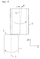
- FIG. 1 a cylindrical workpiece 1 is shown, which rotates about its longitudinal axis 3 in the clockwise direction.
- the workpiece 1 is held by a workpiece holder which is in FIG. 1 not shown.
- An end face 5 of the workpiece 1 is processed by means of a cup wheel 7.
- the axis of rotation of the cup wheel 7 is parallel to the Z-axis.
- the cup wheel 7 is attached to a tool spindle, not shown, and is offset by a drive, also not shown in a counterclockwise rotational movement.
- the cup wheel 7 must grind a center 7 of the workpiece 1. To ensure this, it is usually necessary that the cup wheel 7 is movable in the direction of the X-axis relative to the workpiece 1. Furthermore, the longitudinal axis 3 of the workpiece 1 and a longitudinal axis 9 of the cup wheel 7 must be parallel to each other.
- FIG. 2 is a front view of the in FIG. 1 shown configuration shown. Same components are provided with the same reference numerals and it is the respect FIG. 1 Said accordingly.
- the front view according to FIG. 2 shows an XZ plane in the coordinate system according to FIG. 1 ,
- an inclination angle ⁇ shown in FIG. 2 .
- This inclination angle ⁇ is intended to illustrate a pivoting of the longitudinal axis 9 of the cup wheel 7 or a pivoting of the longitudinal axis of the tool spindle, not shown, in which the cup wheel 7 is rotatably mounted.
- the inclination angle ⁇ therefore describes a rotation or pivoting of a longitudinal axis 9 of the tool spindle in an XZ plane.
- the plane surface 5 of the workpiece can be flat, concave or convex.
- FIG. 3 is a side view of in FIG. 1 described configuration.
- the FIG. 3 thus shows a YZ plane.
- the longitudinal axis 9 of the cup wheel 7 and the tool spindle in the YZ plane parallel to the longitudinal axis 3 of the workpiece 1.
- a concave end face can offer advantages if the end face is designed as a sealing surface. In the case of a concave end face, this results in a sealing edge with locally very high surface pressure on the outer diameter of the workpiece, which improves the seal and makes it possible in part. This is especially true for components or seals, which are exposed to high pressure loads. This is the case, for example, in injection systems of internal combustion engines.
- turntables are often used in planfinishing on which, for example, four workpiece holders are arranged. By turning the turntable by 90 °, the workpieces located in the workpiece holders are moved from one processing station to a next processing station. In a first processing station, for example, the Workpiece holder are loaded with a workpiece. In a second processing station, a roughing of the end face could take place, while in a third processing station, the finishing of the end face is carried out. In a fourth processing station, the workpiece is removed from the workpiece holder.
- the angle of inclination ⁇ and the guide angle ⁇ can be used not only for selectively influencing the geometry of the end face 5 and the microsection, but they can also be used to misalignment between the longitudinal axis 3 of the workpiece 1 and the longitudinal axis 9 of the tool spindle in the ZX Level and / or the ZY plane.
- a machine tool according to the preamble of claim 1 is known in which the tool spindle is hingedly connected to the frame via a hinge. With the help of a ball screw drive, the tool spindle can be pivoted relative to the workpiece.
- the invention has for its object to provide devices for aligning and / or adjusting a tool spindle, which allow targeted control of the geometry of the machined surface (flat, concave or convex) and the targeted influencing properties of the surface (micrograph). In addition, systematic errors of the machine tool to be eliminated by appropriate alignment of the tool spindle.
- a device for aligning a tool spindle according to the preamble of claim 1, in that the means for rotating the first plate relative to the second plate comprise two wedge bars, each of the wedge bars having a wedge surface and a base surface, when the wedge surfaces of both wedge bars are facing each other such that the base of a first wedge bar rests against the first plate and Base surface of a second wedge rod rests on the second plate and the wedge bars are displaceable relative to each other.
- At least one of the wedge bars is displaceable by means of an actuator relative to the other wedge bar.
- the actuator comprises a threaded spindle and the threaded spindle cooperates with a thread, in particular with the thread of a wedge rod. This makes it possible in a simple manner, to rotate the first plate relative to the second plate and thereby to rotate and adjust the Z-axis of the tool spindle relative to a longitudinal axis 3 of the workpiece.
- the hinge between the first and second plate can transmit as large forces and thus does not affect the rigidity of the machine tool, it is provided that the first plate at least one in Direction of the axis of rotation of the hinge extending first paragraph, that the second plate has at least one extending in the direction of the axis of rotation of the hinge second paragraph and that the first plate, the at least one first shoulder, the second plate and the at least one second shoulder at least one prismatic Enclose hinge body.
- an extremely resilient hinge is formed in a simple manner, which is also free of play and also developed in the course of the life of the machine tool no game.
- the hinge body or hinges may preferably be cylindrical, but the invention is not limited to cylindrical hinge bodies.
- square cross sections would be possible, wherein the side edges of the square cross section may preferably be slightly curved.
- spring elements are provided whose spring forces the first plate and the second plate to move toward each other.
- the spring elements comprise compression springs, in particular disc springs or coil springs, and clamping screws.
- the clamping screws protrude through the first and the second plate.
- the compression springs are supported at one end against a head of the clamping screws and at the other end against one of the plates.
- At least one spring element is arranged in the region of the hinge and this at least one spring element, the first plate, the at least one first shoulder, the second plate and the holds at least a second paragraph in abutment with the at least one prismatic hinge body.
- At least one spring element is arranged at a distance from the hinge and this at least one spring element holds the first plate and the second plate in contact with the means for rotating the first plate relative to the second plate.
- both the hinge is free of play and wear in the hinge is compensated automatically. Furthermore, it is achieved that the first plate and the second plate are always held in contact with the means for rotating the first plate relative to the second plate and also characterized in this area a play-free connection is present.
- FIGS. 1 to 3 were already explained in the introduction to the description.
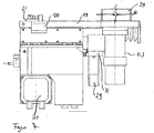
- FIG. 4 is a part of a machine tool with a tool spindle 11 shown.
- this tool spindle is the in the FIGS. 1 to 3 shown cup wheel 7 or another tool clamped.
- a drive of the tool spindle 11 is in FIG. 4 provided with the reference numeral 13.
- the carriage guide 15 is attached indirectly to a plate 19.
- the plate 19 is clamped by means of clamping claws 20 on a machine frame, not shown.
- FIG. 5 shows a different isometry of the tool spindle according to FIG. 4
- Out FIG. 5 is good to see that between the tool spindle 11 and the plate 19 is still a slide guide 27 is provided so that the tool spindle 11 in the direction of the X-axis relative to the machine frame, not shown, is movable. Even with the carriage guide 27, a large part of the same is covered by a bellows 17.
- a planetary gear 31 is flanged, which serves to reduce the speed and to increase the torque of the rotary drive 29.
- the rotary drive 29 is preferably designed as an electric stepper motor.
- FIG. 6 A simplified embodiment of a device for aligning the tool spindle by means of an eccentric is in FIG. 6 and is explained below. No protection is claimed for this device with this patent application.
- FIG. 6 is a machine frame 33, on which the base plate 19 is fixed by means of the clamping claws 20, visible.
- the base plate 19 without tool spindle 11 and the slide guides 15 and 27 are shown in order to better explain the first embodiment of a device according to the invention not for aligning the tool spindle.
- the plate 19 is clamped by means of three clamping claws 20 on the machine frame 33.
- These clamping claws 20 can be loosened if necessary, so that a rotation of the plate 19 about the pivot point formed by the bearing pin 21 is possible.
- the clamping claws 20 exert a clamping force, on the one hand so large that an unwanted rotation of the plate 19 relative to the machine frame 33 does not take place and on the other hand, a rotation of the plate 19 by means of an eccentric is possible without the Spannpratzen 20 to solve.
- FIG. 6 Top right in FIG. 6 one of an eccentric shaft 35 is shown with an eccentric 25.
- the eccentric shaft 35 is rotatably supported in the plate 19, while the eccentric 25 dips into a corresponding slot 37 in the machine frame 33.
- By rotating the eccentric shaft 35 it is possible to rotate the plate 19 about the fixed by the bearing pin 21 pivot point relative to the machine frame 33. This rotational movement is in plan view in the lower part of FIG. 6 indicated by a double arrow 39.
- the eccentric 23 In order to be able to carry out the adjustment or alignment of the tool spindle 11 fully automatically and with the aid of the machine control, in the exemplary embodiment according to FIG FIGS. 4 and 5 the eccentric 23 provided.
- the eccentric 25 does not dive directly into a slot in the machine frame 33, but this slot is in a separate eccentric housing 39 (see FIGS. 4 and 5 ) intended.
- This eccentric housing 39 is screwed to the machine frame, not shown.
- An advantage of this embodiment of a device not according to the invention for aligning a tool spindle is that the rotational movement of the plate 19, which is indeed used ultimately for aligning the tool spindle 11, takes place about an axis which extends perpendicular to the plate 19. In the in the FIGS. 4 and 5 As shown, rotation about the Y-axis takes place while the plate 19 extends substantially in the XZ-plane.
- FIG. 7 shows a plan view of the embodiment according to the FIGS. 4 and 5 , which serves to clarify what has been said.
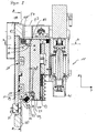
- FIG. 8 shows a section in the YZ plane through the in the FIGS. 4 and 5 illustrated machine tool.
- a first plate 45, a second plate 47 and the carriage guide 27 are arranged in the direction of the X-axis.
- the first plate 45 and the second plate 47 form essential elements of the device according to the invention for aligning a tool spindle 11, which in the following in connection with the FIGS. 8 and 9 is explained in more detail.
- the first plate 45 and the second plate 47 are rotatably connected to each other by a hinge 49.
- the axis of rotation formed by the hinge 49 extends perpendicular to the plane of the drawing, that is, in the direction of the X-axis. This makes it possible, by a guide angle ⁇ relative to the second plate 47 and thus also with respect to the Machine frame (not shown) to rotate in the XZ plane or to pivot.
- the hinge 49 is at the in FIG. 8 in the embodiment shown in section constructed as follows:
- first plate 45 On the first plate 45, a first shoulder 51 is formed. Opposite, a second shoulder 53 is formed on the second plate 47.
- the first plate 45 and the first shoulder 51 on one side and the second plate 47 and the second shoulder 53 on the other side enclose one or more cylindrically shaped prismatic hinge bodies 55 arranged one behind the other.
- the hinge body 55 may be, for example, a hardened cylindrical steel bolt extending in the direction of the X-axis as far as the first plate 45 and the second plate 47 are long.
- hinge bodies 55 it is of course also possible to arrange a plurality of hinge bodies in succession in the direction of the X-axis. Number and length and diameter of the hinge body 55 is to be selected and measured depending on the expected loads of the hinge 49.
- the hinge 49 of the invention is free of play and can form no play between the first plate 45 and the second plate 47 by wear, a plurality of spring elements 57, of which in FIG. 8 only one is visible, arranged over the length of the hinge 49 according to the invention.
- the spring elements 57 comprise a clamping screw 59, of which only the head is visible, and a plurality of disc springs 61.
- the clamping screw is through a through hole (not shown) inserted in the second plate 47 and screwed into an internal thread (not shown) in the first plate 45. Where the clamping screw 59 intersects the hinge body 55, the hinge body 55 is interrupted.
- the clamping screw 59 is rotated so far against the disc springs 61 until the desired bias has been reached. Since the clamping element 45 encloses an angle of approximately 45 ° with the contact surfaces of the hinge body 55 on the first and second plates 45, 47 and the first and second paragraphs 51 and 53, it is ensured that the hinge body 55 always bears against all four contact surfaces and thus the backlash is always guaranteed both in the direction of the Y-axis and in the direction of the Z-axis.
- first plate 45 In order to rotate the first plate 45 relative to the second plate 47, means for rotating the first plate 45 relative to the second plate 47 are provided in the upper region of the first plate 45 and the second plate 47.
- These means for turning comprise a first wedge bar 65 and a second wedge bar 67. The operation of these wedge bars will be described below with reference to FIGS FIG. 9 explained.
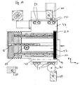
- FIG. 9 makes a cut along the line AA in FIG. 8 In this sectional view, the carriage guide 15 is clearly visible in the direction of the Z-axis. From the FIG. 9 It will be understood that the first wedge bar 65 is embedded in the first plate 45 while the second wedge bar 67 is embedded in the second plate 47.
- the wedge bars each have a base 69 and a wedge surface 71. With their base surfaces 69, 71 are the wedge bars 65 and 67 in the corresponding grooves (without reference numerals) in the first Plate 45 and the second plate 47 on.
- the wedge surfaces (without reference numerals) of the wedge bars 65 and 67 rest on each other, so that the base surfaces of the wedge bars 65 and 67 result in parallel to each other and by a relative movement of the first wedge rod 65 to the second wedge bar 67, the distance of the base surfaces 69 and 71 is variable ,
- the second wedge bar 67 is fixedly connected to the second plate 47, while the first wedge bar 65 is reciprocable by a drive 69 in the direction of the X-axis.
- the rotary drive 73 comprises a stepper motor 75, a coupling 77 and a threaded spindle 79, which cooperates with a corresponding internal thread in the first wedge rod 65.
- At least one spring element 57 is also provided in the region of the means for rotating the first plate.
- This spring element 57 works like the spring elements 57 arranged in the region of the hinges.
- FIG. 10 is a section along the line BB (see FIG. 8 ).
- BB see FIG. 8
- this illustration which is a view from the rear onto the second plate 47, a total of eight spring elements 57 are clearly visible.
- Four of the Spring elements are located in the region of the hinge 49, while the other four spring elements 57 are arranged in the upper part of the second plate 47 in the region of the wedge bars.
- FIG. 11 a section through the drive of the pinion 83 is shown. From the FIG. 11 It can be seen that the rotary drive 29 and the planetary gear 31 via a coupling 85 with a pinion shaft 87 on which the pinion 83 is rotatably attached, are connected. Thus, it is possible to move the tool spindle 11 in the direction of the X-axis by suitable driving of the stepping motor 29. This is necessary, for example, if the diameter of the cup wheel 7 is changed and the cup wheel 7 is to cover the center 8 of the end face 5 of the workpiece (see FIG. 1 ).
- FIG. 12 shows an enlarged view of the pinion drive.
- the device according to the invention for aligning the tool spindle 11 provides a possibility for each installation space situation to pivot the tool spindle.
- the first embodiment which does not correspond to the claimed invention, is based on a bearing pin 21 and an eccentric drive and causes the plate 19 and with it the tool spindle 11 makes a rotational movement about an axis which is perpendicular to the plate 19.
- two plates 45 and 47 are connected together at one edge via a hinge. By rotating these two plates against each other, a rotational movement about an axis of rotation can take place, which runs parallel to the plates.
- Both device can, like the FIGS. 4 to 11 occupy, be combined in a confined space and almost no dead volume. As a result, both the inclination angle ⁇ and the guide angle ⁇ can be set in a machine tool.
Landscapes
- Engineering & Computer Science (AREA)
- Mechanical Engineering (AREA)
- Machine Tool Units (AREA)
- Gripping On Spindles (AREA)
Claims (13)
- Dispositif pour orienter une broche porte-outil (11) comportant une première plaque (19), la broche porte-outil (11) étant fixée à la première plaque (45) au moins de manière indirecte, comportant une deuxième plaque (47), la deuxième plaque (47) étant fixée à un châssis de machine (33) au moins de manière indirecte, la première plaque (45) étant montée rotative par rapport à la deuxième plaque (47) au moyen d'une charnière (49), et comportant des moyens permettant l'entraînement en rotation de la première plaque (45) par rapport à la deuxième plaque (47), caractérisé en ce que les moyens permettant l'entraînement en rotation de la première plaque (45) par rapport à la deuxième plaque (47) comprennent deux barres trapézoïdales (65, 67), en ce que chacune des barres trapézoïdales (65, 67) présente une surface inclinée et une surface de base (69, 71), en ce que les surfaces inclinées des deux barres trapézoïdales (65, 67) sont en regard l'une de l'autre, en ce que la surface de base (69) d'une première barre trapézoïdale (65) prend appui sur la première plaque (45), en ce que la surface de base (71) d'une deuxième barre trapézoïdale (67) prend appui sur la deuxième plaque (47), et en ce que les barres trapézoïdales (65, 67) peuvent coulisser l'une par rapport à l'autre.
- Dispositif selon la revendication 1, caractérisé en ce que l'une des barres trapézoïdales (65, 67) peut coulisser par rapport à l'autre barre trapézoïdale (67, 65) au moyen d'un actionneur.
- Dispositif selon la revendication 2, caractérisé en ce que l'actionneur comprend une broche filetée (79) et en ce que la broche filetée (79) coopère avec un filetage, notamment un taraudage que présente une barre trapézoïdale (65).
- Dispositif selon la revendication 3, caractérisé en ce que la broche filetée (79) peut être entraînée par un moteur électrique, notamment un moteur pas à pas (75) ou un servomoteur triphasé avec commande d'axes numérique.
- Dispositif selon la revendication 4, caractérisé en ce qu'il est prévu, entre la broche filetée (79) et le moteur électrique (75), un démultiplicateur, notamment un engrenage planétaire (31).
- Dispositif selon l'une des revendications précédentes, caractérisé en ce que la première plaque (45) présente au moins un épaulement (51) s'étendant dans la direction de l'axe de rotation de la charnière (49), en ce que la deuxième plaque (47) présente au moins un deuxième épaulement (53) s'étendant dans la direction de l'axe de rotation de la charnière, en ce que la première plaque (45), le ou les premier(s) épaulement(s) (51), la deuxième plaque (47) et le ou les deuxième(s) épaulement(s) (53) entourent au moins un corps de charnière en forme de prisme (55).
- Dispositif selon la revendication 6, caractérisé en ce que le ou les corps de charnière (55) sont de forme cylindrique.
- Dispositif selon l'une quelconque des revendications précédentes, caractérisé en ce que sont prévus des éléments formant ressort (57) et en ce que les forces de rappel élastique tendent à rapprocher la première plaque (45) de la deuxième plaque.
- Dispositif selon la revendication 8, caractérisé en ce que les éléments formant ressort (57) comportent des ressorts de pression, notamment des rondelles-ressorts (61), et des vis de serrage (59), en ce que les vis de serrage (59) traversent la première plaque (45) et la deuxième plaque (47), et en ce que les ressorts de pression (61) prennent appui à une extrémité contre une tête des vis de serrage (59) et à l'autre extrémité contre l'une des plaques (45, 47).
- Dispositif selon l'une des revendications 6 à 9, caractérisé en ce qu'au moins un élément formant ressort (57) est disposé dans la région de la charnière (49), et en ce que ce ou ces élément(s) formant ressort (57) maintiennent la première plaque (45), le ou les premier(s) épaulement(s) (51), la deuxième plaque (47) et le ou les deuxième(s) épaulement(s) (53) en contact avec le ou les corps de charnière en forme de prisme (55).
- Dispositif selon l'une quelconque des revendications précédentes, caractérisé en ce qu'au moins un élément formant ressort (57) est disposé à distance de la charnière, et en ce que ce ou ces élément(s) formant ressort (57) maintiennent la première plaque (45) et la deuxième plaque (47) en contact avec les moyens permettant l'entraînement en rotation de la première plaque (45) par rapport à la deuxième plaque (47).
- Dispositif selon l'une quelconque des revendications précédentes, caractérisé en ce que la broche porte-outil (11) est guidée mobile (27) le long de la plaque (19) dans la direction de l'axe X, et en ce qu'il est prévu un dispositif d'entraînement permettant de déplacer la broche porte-outil (11) dans la direction de l'axe X.
- Dispositif selon l'une quelconque des revendications précédentes, caractérisé en ce que le dispositif d'entraînement permettant de déplacer la broche porte-outil (11) dans la direction de l'axe X comprend une crémaillère (81), un pignon (83), un mécanisme d'entraînement en rotation (29) et/ou un engrenage planétaire (31).
Applications Claiming Priority (2)
| Application Number | Priority Date | Filing Date | Title |
|---|---|---|---|
| DE102006004747A DE102006004747A1 (de) | 2006-02-02 | 2006-02-02 | Vorrichtung zum Einstellen einer Werkzeugspindel |
| EP07001794A EP1815940A3 (fr) | 2006-02-02 | 2007-01-26 | Dispositif destiné au réglage d'une broche d'outil |
Related Parent Applications (1)
| Application Number | Title | Priority Date | Filing Date |
|---|---|---|---|
| EP07001794A Division EP1815940A3 (fr) | 2006-02-02 | 2007-01-26 | Dispositif destiné au réglage d'une broche d'outil |
Publications (2)
| Publication Number | Publication Date |
|---|---|
| EP1878534A1 EP1878534A1 (fr) | 2008-01-16 |
| EP1878534B1 true EP1878534B1 (fr) | 2009-03-11 |
Family
ID=38038603
Family Applications (2)
| Application Number | Title | Priority Date | Filing Date |
|---|---|---|---|
| EP07001794A Withdrawn EP1815940A3 (fr) | 2006-02-02 | 2007-01-26 | Dispositif destiné au réglage d'une broche d'outil |
| EP07021237A Expired - Fee Related EP1878534B1 (fr) | 2006-02-02 | 2007-01-26 | Dispositif pour orienter une broche porte-outil comprenant une charnière |
Family Applications Before (1)
| Application Number | Title | Priority Date | Filing Date |
|---|---|---|---|
| EP07001794A Withdrawn EP1815940A3 (fr) | 2006-02-02 | 2007-01-26 | Dispositif destiné au réglage d'une broche d'outil |
Country Status (2)
| Country | Link |
|---|---|
| EP (2) | EP1815940A3 (fr) |
| DE (2) | DE102006004747A1 (fr) |
Families Citing this family (6)
| Publication number | Priority date | Publication date | Assignee | Title |
|---|---|---|---|---|
| DE202006017178U1 (de) * | 2006-11-10 | 2007-01-25 | Thielenhaus Technologies Gmbh | Werkzeugschlittenanordnung |
| DE102007050482B4 (de) | 2007-10-19 | 2017-08-24 | Thielenhaus Technologies Gmbh | Verfahren und Vorrichtung zur Finishbearbeitung |
| ATE552069T1 (de) | 2010-02-08 | 2012-04-15 | Supfina Grieshaber Gmbh & Co | Rotationsfinishvorrichtung und verfahren zur einrichtung oder zum betrieb einer rotationsfinishvorrichtung |
| CN102821894B (zh) * | 2012-04-03 | 2013-11-27 | 山崎马扎克公司 | 复合加工中心的车削主轴部件 |
| DE102014223101A1 (de) * | 2014-11-12 | 2016-05-12 | Supfina Grieshaber Gmbh & Co. Kg | Werkzeugmaschineneinheit zur Ausrichtung eines Werkzeugs oder eines Werkstücks |
| DE102016014515B4 (de) | 2016-12-07 | 2018-12-27 | Hochschule Magdeburg-Stendal | Vorrichtung zum Rotationsfinishen von Werkstückoberflächen |
Family Cites Families (10)
| Publication number | Priority date | Publication date | Assignee | Title |
|---|---|---|---|---|
| DE1117359B (de) * | 1958-04-16 | 1961-11-16 | Hans Deckel Dr Ing | Aufspanntisch |
| US3276329A (en) * | 1965-07-01 | 1966-10-04 | American Science & Eng Inc | Machine tools |
| US4190948A (en) * | 1978-12-06 | 1980-03-04 | Kearney & Trecker Corporation | Vertical spindle machine tool with tiltable spindle and tiltable automatic tool changer |
| DE7934741U1 (de) * | 1979-12-11 | 1981-05-27 | Werkzeugmaschinenfabrik Adolf Waldrich Coburg Gmbh & Co, 8630 Coburg | Vorrichtung zum zentrieren und indexieren von werkzeugmaschinenteilen, insbesondere winkelfraeskoepfen am spindelschlitten einer fraesmaschine |
| CH667408A5 (de) * | 1985-05-20 | 1988-10-14 | Istema Ind Elektrotechnik Und | Bausatz zur montage von teilen und verwendung desselben. |
| DE3928113C1 (en) * | 1989-08-25 | 1991-01-31 | Maschinenfabrik Ernst Thielenhaus Gmbh, 5600 Wuppertal, De | Precision grinding machine tool holder - has top part swinging on horizontal axis while workpiece holder rotates on vertical axis |
| DE4424310C2 (de) * | 1994-07-09 | 1996-05-02 | Weinig Michael Ag | Maschine zum Bearbeiten von Werkstücken aus Holz, Kunststoff und dergleichen |
| CH692010A5 (de) * | 1997-09-09 | 2002-01-15 | Erowa Ag | Vorrichtung zum Aufspannen und Ausrichten eines Werkzeugs oder Werkstücks. |
| DE19846260A1 (de) * | 1998-10-07 | 2000-04-13 | Schneider Gmbh & Co Kg | Vorrichtung zum Bearbeiten optischer Linsen durch Schleifen und Polieren |
| DE10019788A1 (de) * | 2000-04-20 | 2001-10-31 | Index Werke Kg Hahn & Tessky | Werkzeugmaschine |
-
2006
- 2006-02-02 DE DE102006004747A patent/DE102006004747A1/de not_active Ceased
-
2007
- 2007-01-26 EP EP07001794A patent/EP1815940A3/fr not_active Withdrawn
- 2007-01-26 DE DE502007000502T patent/DE502007000502D1/de active Active
- 2007-01-26 EP EP07021237A patent/EP1878534B1/fr not_active Expired - Fee Related
Also Published As
| Publication number | Publication date |
|---|---|
| DE102006004747A1 (de) | 2007-08-09 |
| EP1815940A3 (fr) | 2007-10-10 |
| EP1815940A2 (fr) | 2007-08-08 |
| DE502007000502D1 (de) | 2009-04-23 |
| EP1878534A1 (fr) | 2008-01-16 |
Similar Documents
| Publication | Publication Date | Title |
|---|---|---|
| EP2688710B1 (fr) | Dispositif de meuleuse a montage pivotant d'une unite de broche porte-meule et procede permettant de faire pivoter une unite de broche porte-meule sur une meuleuse | |
| EP2540438B1 (fr) | Lunette | |
| EP1878534B1 (fr) | Dispositif pour orienter une broche porte-outil comprenant une charnière | |
| EP2338640A1 (fr) | Machine de meulage de pièces optiques, en particuliere de verres à lunettes en plastique | |
| DE102009006797A1 (de) | Linsenbearbeitungsvorrichtung | |
| EP0547554A1 (fr) | Appareil de serrage pour usiner en muti-faces | |
| EP3760352A1 (fr) | Mandrin á compensation pour le serrage de pièces dans centres d'usinage | |
| EP3778118B1 (fr) | Machine-outil pourvue de deux broches de travail | |
| EP1038617B1 (fr) | Porte-outil et machine-outil | |
| EP0962280B1 (fr) | Dispositif d'alignement | |
| DE19527507C1 (de) | Werkstückspannvorrichtung für eine Werkzeugmaschine für die Mehrseitenbearbeitung von Werkstücken | |
| EP2623243B1 (fr) | Machine à affûter des lames de scie circulaires | |
| EP3509781A2 (fr) | Outil d'usinage par enlèvement de copeaux multi-lames et procédé d'usinage d'un chemin laser | |
| EP2062705A1 (fr) | Dispositif et procédé de fabrication de diaphragmes à fentes pour le rayonnement hautement énergétique | |
| DE3701446A1 (de) | Innenrundschleifmaschine | |
| WO2014041130A1 (fr) | Outil d'usinage de pièces par enlèvement de matière | |
| EP1577040B1 (fr) | Dispositif d'usinage de pièces, notamment pour des pièces pourvues de dents | |
| EP3251788B1 (fr) | Dispositif de soutien d'une pièce à usiner | |
| EP1025953A1 (fr) | Machine-outil | |
| EP3524386B1 (fr) | Dispositif de soutien d'une pièce à usiner | |
| EP1559490B1 (fr) | Porte outil | |
| DE4236686C1 (de) | Fräseinrichtung mit einem Werkzeughalter für einen Werkzeugträger einer Drehmaschine | |
| EP1514623B1 (fr) | Machine-outil et porte-outil associé | |
| AT500168B1 (de) | Justiervorrichtung für einen werkzeughalter einer cnc - drehmaschine | |
| EP2686120B1 (fr) | Dispositif de positionnement d'outil sur une presse à cintrer |
Legal Events
| Date | Code | Title | Description |
|---|---|---|---|
| PUAI | Public reference made under article 153(3) epc to a published international application that has entered the european phase |
Free format text: ORIGINAL CODE: 0009012 |
|
| AC | Divisional application: reference to earlier application |
Ref document number: 1815940 Country of ref document: EP Kind code of ref document: P |
|
| AK | Designated contracting states |
Kind code of ref document: A1 Designated state(s): AT BE BG CH CY CZ DE DK EE ES FI FR GB GR HU IE IS IT LI LT LU LV MC NL PL PT RO SE SI SK TR |
|
| AX | Request for extension of the european patent |
Extension state: AL BA HR MK YU |
|
| 17P | Request for examination filed |
Effective date: 20080714 |
|
| GRAP | Despatch of communication of intention to grant a patent |
Free format text: ORIGINAL CODE: EPIDOSNIGR1 |
|
| AKX | Designation fees paid |
Designated state(s): DE FR GB |
|
| GRAS | Grant fee paid |
Free format text: ORIGINAL CODE: EPIDOSNIGR3 |
|
| GRAA | (expected) grant |
Free format text: ORIGINAL CODE: 0009210 |
|
| AC | Divisional application: reference to earlier application |
Ref document number: 1815940 Country of ref document: EP Kind code of ref document: P |
|
| AK | Designated contracting states |
Kind code of ref document: B1 Designated state(s): DE FR GB |
|
| REG | Reference to a national code |
Ref country code: GB Ref legal event code: FG4D Free format text: NOT ENGLISH |
|
| REF | Corresponds to: |
Ref document number: 502007000502 Country of ref document: DE Date of ref document: 20090423 Kind code of ref document: P |
|
| PLBE | No opposition filed within time limit |
Free format text: ORIGINAL CODE: 0009261 |
|
| STAA | Information on the status of an ep patent application or granted ep patent |
Free format text: STATUS: NO OPPOSITION FILED WITHIN TIME LIMIT |
|
| 26N | No opposition filed |
Effective date: 20091214 |
|
| PGFP | Annual fee paid to national office [announced via postgrant information from national office to epo] |
Ref country code: GB Payment date: 20101231 Year of fee payment: 5 |
|
| GBPC | Gb: european patent ceased through non-payment of renewal fee |
Effective date: 20120126 |
|
| PG25 | Lapsed in a contracting state [announced via postgrant information from national office to epo] |
Ref country code: GB Free format text: LAPSE BECAUSE OF NON-PAYMENT OF DUE FEES Effective date: 20120126 |
|
| REG | Reference to a national code |
Ref country code: FR Ref legal event code: PLFP Year of fee payment: 10 |
|
| REG | Reference to a national code |
Ref country code: FR Ref legal event code: PLFP Year of fee payment: 11 |
|
| PGFP | Annual fee paid to national office [announced via postgrant information from national office to epo] |
Ref country code: FR Payment date: 20170124 Year of fee payment: 11 |
|
| PGFP | Annual fee paid to national office [announced via postgrant information from national office to epo] |
Ref country code: DE Payment date: 20180124 Year of fee payment: 12 |
|
| PG25 | Lapsed in a contracting state [announced via postgrant information from national office to epo] |
Ref country code: FR Free format text: LAPSE BECAUSE OF NON-PAYMENT OF DUE FEES Effective date: 20180131 |
|
| REG | Reference to a national code |
Ref country code: FR Ref legal event code: ST Effective date: 20180928 |
|
| REG | Reference to a national code |
Ref country code: DE Ref legal event code: R119 Ref document number: 502007000502 Country of ref document: DE |
|
| PG25 | Lapsed in a contracting state [announced via postgrant information from national office to epo] |
Ref country code: DE Free format text: LAPSE BECAUSE OF NON-PAYMENT OF DUE FEES Effective date: 20190801 |