EP1522355B1 - Procede, systeme et conteneur pour recycler des ressources - Google Patents
Procede, systeme et conteneur pour recycler des ressources Download PDFInfo
- Publication number
- EP1522355B1 EP1522355B1 EP03736245A EP03736245A EP1522355B1 EP 1522355 B1 EP1522355 B1 EP 1522355B1 EP 03736245 A EP03736245 A EP 03736245A EP 03736245 A EP03736245 A EP 03736245A EP 1522355 B1 EP1522355 B1 EP 1522355B1
- Authority
- EP
- European Patent Office
- Prior art keywords
- container
- carbon
- product
- gas
- oxygen
- Prior art date
- Legal status (The legal status is an assumption and is not a legal conclusion. Google has not performed a legal analysis and makes no representation as to the accuracy of the status listed.)
- Expired - Lifetime
Links
- 238000004064 recycling Methods 0.000 title claims abstract description 39
- 238000000034 method Methods 0.000 title claims description 44
- OKTJSMMVPCPJKN-UHFFFAOYSA-N Carbon Chemical compound [C] OKTJSMMVPCPJKN-UHFFFAOYSA-N 0.000 claims abstract description 150
- 239000007789 gas Substances 0.000 claims abstract description 86
- 229910052799 carbon Inorganic materials 0.000 claims abstract description 79
- 239000012298 atmosphere Substances 0.000 claims abstract description 46
- 229910021393 carbon nanotube Inorganic materials 0.000 claims abstract description 30
- 239000002041 carbon nanotube Substances 0.000 claims abstract description 30
- 239000000460 chlorine Substances 0.000 claims abstract description 24
- 229910052801 chlorine Inorganic materials 0.000 claims abstract description 24
- ZAMOUSCENKQFHK-UHFFFAOYSA-N Chlorine atom Chemical compound [Cl] ZAMOUSCENKQFHK-UHFFFAOYSA-N 0.000 claims abstract description 23
- 238000010438 heat treatment Methods 0.000 claims abstract description 20
- XLYOFNOQVPJJNP-UHFFFAOYSA-N water Substances O XLYOFNOQVPJJNP-UHFFFAOYSA-N 0.000 claims abstract description 16
- 239000003575 carbonaceous material Substances 0.000 claims description 24
- 238000004519 manufacturing process Methods 0.000 claims description 24
- 150000001875 compounds Chemical class 0.000 claims description 19
- 238000001816 cooling Methods 0.000 claims description 15
- 239000012530 fluid Substances 0.000 claims description 8
- 239000011261 inert gas Substances 0.000 claims description 6
- 238000006243 chemical reaction Methods 0.000 claims 2
- IJGRMHOSHXDMSA-UHFFFAOYSA-N Atomic nitrogen Chemical compound N#N IJGRMHOSHXDMSA-UHFFFAOYSA-N 0.000 abstract description 97
- 229910052757 nitrogen Inorganic materials 0.000 abstract description 45
- CURLTUGMZLYLDI-UHFFFAOYSA-N Carbon dioxide Chemical compound O=C=O CURLTUGMZLYLDI-UHFFFAOYSA-N 0.000 abstract description 28
- QVGXLLKOCUKJST-UHFFFAOYSA-N atomic oxygen Chemical compound [O] QVGXLLKOCUKJST-UHFFFAOYSA-N 0.000 abstract description 20
- 229910052760 oxygen Inorganic materials 0.000 abstract description 20
- 239000001301 oxygen Substances 0.000 abstract description 20
- 239000001569 carbon dioxide Substances 0.000 abstract description 14
- 229910002092 carbon dioxide Inorganic materials 0.000 abstract description 14
- 150000002013 dioxins Chemical class 0.000 abstract description 12
- 229910052751 metal Inorganic materials 0.000 abstract description 11
- 239000002184 metal Substances 0.000 abstract description 11
- 230000004913 activation Effects 0.000 abstract description 5
- 150000002739 metals Chemical class 0.000 abstract description 4
- -1 inert carbon) Chemical compound 0.000 abstract 1
- 239000002699 waste material Substances 0.000 description 46
- MWUXSHHQAYIFBG-UHFFFAOYSA-N Nitric oxide Chemical compound O=[N] MWUXSHHQAYIFBG-UHFFFAOYSA-N 0.000 description 12
- 230000008569 process Effects 0.000 description 9
- 239000012299 nitrogen atmosphere Substances 0.000 description 8
- 239000010920 waste tyre Substances 0.000 description 8
- 229910001873 dinitrogen Inorganic materials 0.000 description 7
- 238000000605 extraction Methods 0.000 description 7
- 230000008901 benefit Effects 0.000 description 5
- 238000002485 combustion reaction Methods 0.000 description 5
- 238000010924 continuous production Methods 0.000 description 5
- 230000000694 effects Effects 0.000 description 5
- 239000000126 substance Substances 0.000 description 5
- 238000010586 diagram Methods 0.000 description 4
- TXKMVPPZCYKFAC-UHFFFAOYSA-N disulfur monoxide Inorganic materials O=S=S TXKMVPPZCYKFAC-UHFFFAOYSA-N 0.000 description 4
- 239000007788 liquid Substances 0.000 description 4
- XTQHKBHJIVJGKJ-UHFFFAOYSA-N sulfur monoxide Chemical compound S=O XTQHKBHJIVJGKJ-UHFFFAOYSA-N 0.000 description 4
- XEEYBQQBJWHFJM-UHFFFAOYSA-N Iron Chemical compound [Fe] XEEYBQQBJWHFJM-UHFFFAOYSA-N 0.000 description 3
- HEMHJVSKTPXQMS-UHFFFAOYSA-M Sodium hydroxide Chemical compound [OH-].[Na+] HEMHJVSKTPXQMS-UHFFFAOYSA-M 0.000 description 3
- 239000000110 cooling liquid Substances 0.000 description 3
- 229920001971 elastomer Polymers 0.000 description 3
- 238000011049 filling Methods 0.000 description 3
- 229910001385 heavy metal Inorganic materials 0.000 description 3
- 238000009434 installation Methods 0.000 description 3
- 239000000463 material Substances 0.000 description 3
- 229920003023 plastic Polymers 0.000 description 3
- 239000004033 plastic Substances 0.000 description 3
- 230000009467 reduction Effects 0.000 description 3
- 239000011347 resin Substances 0.000 description 3
- 229920005989 resin Polymers 0.000 description 3
- 239000004071 soot Substances 0.000 description 3
- 230000008016 vaporization Effects 0.000 description 3
- 125000000391 vinyl group Chemical group [H]C([*])=C([H])[H] 0.000 description 3
- 229920002554 vinyl polymer Polymers 0.000 description 3
- LFQSCWFLJHTTHZ-UHFFFAOYSA-N Ethanol Chemical compound CCO LFQSCWFLJHTTHZ-UHFFFAOYSA-N 0.000 description 2
- 238000001241 arc-discharge method Methods 0.000 description 2
- 238000003763 carbonization Methods 0.000 description 2
- 238000007599 discharging Methods 0.000 description 2
- 238000010891 electric arc Methods 0.000 description 2
- 230000005611 electricity Effects 0.000 description 2
- 239000000284 extract Substances 0.000 description 2
- 229910052742 iron Inorganic materials 0.000 description 2
- 239000011148 porous material Substances 0.000 description 2
- 230000001681 protective effect Effects 0.000 description 2
- 239000000523 sample Substances 0.000 description 2
- 239000002356 single layer Substances 0.000 description 2
- 239000013076 target substance Substances 0.000 description 2
- 238000009834 vaporization Methods 0.000 description 2
- KVGZZAHHUNAVKZ-UHFFFAOYSA-N 1,4-Dioxin Chemical compound O1C=COC=C1 KVGZZAHHUNAVKZ-UHFFFAOYSA-N 0.000 description 1
- 239000004215 Carbon black (E152) Substances 0.000 description 1
- VEXZGXHMUGYJMC-UHFFFAOYSA-M Chloride anion Chemical compound [Cl-] VEXZGXHMUGYJMC-UHFFFAOYSA-M 0.000 description 1
- 229910000831 Steel Inorganic materials 0.000 description 1
- 230000003213 activating effect Effects 0.000 description 1
- 239000002154 agricultural waste Substances 0.000 description 1
- 239000003570 air Substances 0.000 description 1
- 239000000956 alloy Substances 0.000 description 1
- 229910045601 alloy Inorganic materials 0.000 description 1
- 238000009835 boiling Methods 0.000 description 1
- AXCZMVOFGPJBDE-UHFFFAOYSA-L calcium dihydroxide Chemical compound [OH-].[OH-].[Ca+2] AXCZMVOFGPJBDE-UHFFFAOYSA-L 0.000 description 1
- 239000000920 calcium hydroxide Substances 0.000 description 1
- 229910001861 calcium hydroxide Inorganic materials 0.000 description 1
- 235000011116 calcium hydroxide Nutrition 0.000 description 1
- 230000003197 catalytic effect Effects 0.000 description 1
- 239000000919 ceramic Substances 0.000 description 1
- 230000008859 change Effects 0.000 description 1
- 239000003610 charcoal Substances 0.000 description 1
- 150000001805 chlorine compounds Chemical class 0.000 description 1
- 230000018044 dehydration Effects 0.000 description 1
- 238000006297 dehydration reaction Methods 0.000 description 1
- 230000006866 deterioration Effects 0.000 description 1
- 238000001035 drying Methods 0.000 description 1
- 239000000428 dust Substances 0.000 description 1
- 230000002708 enhancing effect Effects 0.000 description 1
- 230000007613 environmental effect Effects 0.000 description 1
- 239000010763 heavy fuel oil Substances 0.000 description 1
- 239000001307 helium Substances 0.000 description 1
- 229910052734 helium Inorganic materials 0.000 description 1
- SWQJXJOGLNCZEY-UHFFFAOYSA-N helium atom Chemical compound [He] SWQJXJOGLNCZEY-UHFFFAOYSA-N 0.000 description 1
- 231100000086 high toxicity Toxicity 0.000 description 1
- 229930195733 hydrocarbon Natural products 0.000 description 1
- 150000002430 hydrocarbons Chemical class 0.000 description 1
- 238000010348 incorporation Methods 0.000 description 1
- 230000002401 inhibitory effect Effects 0.000 description 1
- 238000002347 injection Methods 0.000 description 1
- 239000007924 injection Substances 0.000 description 1
- 239000011810 insulating material Substances 0.000 description 1
- 229910052746 lanthanum Inorganic materials 0.000 description 1
- 238000000223 laser vaporisation method Methods 0.000 description 1
- 239000002906 medical waste Substances 0.000 description 1
- VNWKTOKETHGBQD-UHFFFAOYSA-N methane Chemical compound C VNWKTOKETHGBQD-UHFFFAOYSA-N 0.000 description 1
- 230000004048 modification Effects 0.000 description 1
- 238000012986 modification Methods 0.000 description 1
- 238000012544 monitoring process Methods 0.000 description 1
- 230000003472 neutralizing effect Effects 0.000 description 1
- 229910052759 nickel Inorganic materials 0.000 description 1
- 239000010815 organic waste Substances 0.000 description 1
- 230000001590 oxidative effect Effects 0.000 description 1
- 239000003208 petroleum Substances 0.000 description 1
- 238000003825 pressing Methods 0.000 description 1
- 230000005855 radiation Effects 0.000 description 1
- 238000011084 recovery Methods 0.000 description 1
- 230000004044 response Effects 0.000 description 1
- 150000003839 salts Chemical class 0.000 description 1
- 238000000926 separation method Methods 0.000 description 1
- 239000010802 sludge Substances 0.000 description 1
- 239000002689 soil Substances 0.000 description 1
- 239000010959 steel Substances 0.000 description 1
- 230000001629 suppression Effects 0.000 description 1
- 239000013077 target material Substances 0.000 description 1
- 238000005979 thermal decomposition reaction Methods 0.000 description 1
- 230000008646 thermal stress Effects 0.000 description 1
- 231100000331 toxic Toxicity 0.000 description 1
- 230000002588 toxic effect Effects 0.000 description 1
- 239000010891 toxic waste Substances 0.000 description 1
- 231100000419 toxicity Toxicity 0.000 description 1
- 230000001988 toxicity Effects 0.000 description 1
Images

Classifications
-
- B—PERFORMING OPERATIONS; TRANSPORTING
- B09—DISPOSAL OF SOLID WASTE; RECLAMATION OF CONTAMINATED SOIL
- B09B—DISPOSAL OF SOLID WASTE NOT OTHERWISE PROVIDED FOR
- B09B3/00—Destroying solid waste or transforming solid waste into something useful or harmless
-
- B—PERFORMING OPERATIONS; TRANSPORTING
- B82—NANOTECHNOLOGY
- B82Y—SPECIFIC USES OR APPLICATIONS OF NANOSTRUCTURES; MEASUREMENT OR ANALYSIS OF NANOSTRUCTURES; MANUFACTURE OR TREATMENT OF NANOSTRUCTURES
- B82Y30/00—Nanotechnology for materials or surface science, e.g. nanocomposites
-
- B—PERFORMING OPERATIONS; TRANSPORTING
- B82—NANOTECHNOLOGY
- B82Y—SPECIFIC USES OR APPLICATIONS OF NANOSTRUCTURES; MEASUREMENT OR ANALYSIS OF NANOSTRUCTURES; MANUFACTURE OR TREATMENT OF NANOSTRUCTURES
- B82Y40/00—Manufacture or treatment of nanostructures
-
- C—CHEMISTRY; METALLURGY
- C01—INORGANIC CHEMISTRY
- C01B—NON-METALLIC ELEMENTS; COMPOUNDS THEREOF; METALLOIDS OR COMPOUNDS THEREOF NOT COVERED BY SUBCLASS C01C
- C01B32/00—Carbon; Compounds thereof
- C01B32/15—Nano-sized carbon materials
- C01B32/158—Carbon nanotubes
- C01B32/16—Preparation
-
- C—CHEMISTRY; METALLURGY
- C01—INORGANIC CHEMISTRY
- C01B—NON-METALLIC ELEMENTS; COMPOUNDS THEREOF; METALLOIDS OR COMPOUNDS THEREOF NOT COVERED BY SUBCLASS C01C
- C01B32/00—Carbon; Compounds thereof
- C01B32/30—Active carbon
- C01B32/312—Preparation
-
- C—CHEMISTRY; METALLURGY
- C10—PETROLEUM, GAS OR COKE INDUSTRIES; TECHNICAL GASES CONTAINING CARBON MONOXIDE; FUELS; LUBRICANTS; PEAT
- C10B—DESTRUCTIVE DISTILLATION OF CARBONACEOUS MATERIALS FOR PRODUCTION OF GAS, COKE, TAR, OR SIMILAR MATERIALS
- C10B47/00—Destructive distillation of solid carbonaceous materials with indirect heating, e.g. by external combustion
- C10B47/28—Other processes
- C10B47/32—Other processes in ovens with mechanical conveying means
- C10B47/46—Other processes in ovens with mechanical conveying means with trucks, containers, or trays
-
- C—CHEMISTRY; METALLURGY
- C10—PETROLEUM, GAS OR COKE INDUSTRIES; TECHNICAL GASES CONTAINING CARBON MONOXIDE; FUELS; LUBRICANTS; PEAT
- C10B—DESTRUCTIVE DISTILLATION OF CARBONACEOUS MATERIALS FOR PRODUCTION OF GAS, COKE, TAR, OR SIMILAR MATERIALS
- C10B53/00—Destructive distillation, specially adapted for particular solid raw materials or solid raw materials in special form
- C10B53/07—Destructive distillation, specially adapted for particular solid raw materials or solid raw materials in special form of solid raw materials consisting of synthetic polymeric materials, e.g. tyres
-
- C—CHEMISTRY; METALLURGY
- C10—PETROLEUM, GAS OR COKE INDUSTRIES; TECHNICAL GASES CONTAINING CARBON MONOXIDE; FUELS; LUBRICANTS; PEAT
- C10G—CRACKING HYDROCARBON OILS; PRODUCTION OF LIQUID HYDROCARBON MIXTURES, e.g. BY DESTRUCTIVE HYDROGENATION, OLIGOMERISATION, POLYMERISATION; RECOVERY OF HYDROCARBON OILS FROM OIL-SHALE, OIL-SAND, OR GASES; REFINING MIXTURES MAINLY CONSISTING OF HYDROCARBONS; REFORMING OF NAPHTHA; MINERAL WAXES
- C10G1/00—Production of liquid hydrocarbon mixtures from oil-shale, oil-sand, or non-melting solid carbonaceous or similar materials, e.g. wood, coal
- C10G1/10—Production of liquid hydrocarbon mixtures from oil-shale, oil-sand, or non-melting solid carbonaceous or similar materials, e.g. wood, coal from rubber or rubber waste
-
- Y—GENERAL TAGGING OF NEW TECHNOLOGICAL DEVELOPMENTS; GENERAL TAGGING OF CROSS-SECTIONAL TECHNOLOGIES SPANNING OVER SEVERAL SECTIONS OF THE IPC; TECHNICAL SUBJECTS COVERED BY FORMER USPC CROSS-REFERENCE ART COLLECTIONS [XRACs] AND DIGESTS
- Y02—TECHNOLOGIES OR APPLICATIONS FOR MITIGATION OR ADAPTATION AGAINST CLIMATE CHANGE
- Y02P—CLIMATE CHANGE MITIGATION TECHNOLOGIES IN THE PRODUCTION OR PROCESSING OF GOODS
- Y02P20/00—Technologies relating to chemical industry
- Y02P20/10—Process efficiency
-
- Y—GENERAL TAGGING OF NEW TECHNOLOGICAL DEVELOPMENTS; GENERAL TAGGING OF CROSS-SECTIONAL TECHNOLOGIES SPANNING OVER SEVERAL SECTIONS OF THE IPC; TECHNICAL SUBJECTS COVERED BY FORMER USPC CROSS-REFERENCE ART COLLECTIONS [XRACs] AND DIGESTS
- Y02—TECHNOLOGIES OR APPLICATIONS FOR MITIGATION OR ADAPTATION AGAINST CLIMATE CHANGE
- Y02P—CLIMATE CHANGE MITIGATION TECHNOLOGIES IN THE PRODUCTION OR PROCESSING OF GOODS
- Y02P20/00—Technologies relating to chemical industry
- Y02P20/141—Feedstock
- Y02P20/143—Feedstock the feedstock being recycled material, e.g. plastics
-
- Y—GENERAL TAGGING OF NEW TECHNOLOGICAL DEVELOPMENTS; GENERAL TAGGING OF CROSS-SECTIONAL TECHNOLOGIES SPANNING OVER SEVERAL SECTIONS OF THE IPC; TECHNICAL SUBJECTS COVERED BY FORMER USPC CROSS-REFERENCE ART COLLECTIONS [XRACs] AND DIGESTS
- Y02—TECHNOLOGIES OR APPLICATIONS FOR MITIGATION OR ADAPTATION AGAINST CLIMATE CHANGE
- Y02W—CLIMATE CHANGE MITIGATION TECHNOLOGIES RELATED TO WASTEWATER TREATMENT OR WASTE MANAGEMENT
- Y02W30/00—Technologies for solid waste management
- Y02W30/20—Waste processing or separation
Definitions
- the present invention relates to a recycling method and system for waste or the like, a method and system of producing carbon materials such as inert carbon, carbon nanotubes, and activated carbon by utilizing such waste, and a suitable container for such methods and systems.
- Waste disposal has in recent years focused to an ever greater extent on the recycling of wastes to produce usable materials.
- the recycling concept is being gradually realized through segregated disposal of waste and the like.
- satisfactory results have not yet been obtained yet because of strict social and economic restrictions related to labor, facilities, cost and other factors related to the requirements for segregated disposal.
- the emission into the air can be controlled for some extent by incinerating at an adequately high temperature, keeping a constant incineration temperature, using a reburning device, or the like, but further suppression of the emission of dioxins still remains as a problem to be solved.
- a near-future waste disposal system must be a system which can reproduce a large volume of useful resources from waste and be built and operated without involving much time and labor, large facilities, or high cost, and is environmentally friendly without producing or releasing carbon dioxide or dioxins.
- the system described in Japanese Patent No. 2651994 for example, is an example known system which can partly respond to such social demands.
- the disclosed system produces activated carbon from scrap tires by heating the scrap tires in a nitrogen atmosphere not containing oxygen. This system does not produce carbon dioxide because the scrap tires being heated are kept isolated from oxygen and metals such as steel wire and the like contained in the waste tires can be recovered in a non-degraded reusable state.
- the disclosed system is a related to the recycling of scrap tires, and does not release carbon dioxide or the like.
- Document US-A-5673635 discloses a process for recycling organic waste where the waste are introduced in a sealed container as well as an insert gas to remove oxygen from the container. The container is then heated, the gas filtered and stored in a vessel.
- This patented system has a furnace called a carbonization chamber or the like as its basic configuration unit, generally requires installation of many chambers or furnaces including a plurality of carbonization chambers and their incidental reserve chambers or the like, and these chambers or-furnaces must be provided in a sealable configuration which avoids all contact with the air. Therefore, it is facility scale (dimensions and weight), operation costs (power and thermal power costs and labor costs), and the like are all disadvantageously great.
- Such a system can produce activated carbon by treating waste, but requires that the waste be treated in an oxygen-free state so as to change the activated carbon into inert carbon in order to obtain inert carbon.
- the inert carbon e.g., bincho charcoal
- the inert carbon has substantially no pores and a high carbon density and provides a high volume of far infrared ray radiated from carbon elements as compared with activated carbon having many pores and a low carbon density.
- the inert carbon is useful for applications employing far infrared radiation (e.g., a method of using it as the content of an infrared pillow, a method of using it as the contents of infrared concrete, etc.).
- the inert carbon is also useful because carbon nanotubes and the like can be produced by activating the inert carbon. Accordingly, there is great demand for a systemwhich canmass-produce inert carbon by directly obtaining the inert carbon.
- the present invention advantageously provides a recycling method and system capable of recycling waste efficiently in small-scale facilities at a low cost using a method which does not release excess or toxic emissions.
- the present invention also advantageously provides a carbon material manufacturing method and system capable of obtaining inert carbon by recycling high-molecular compounds.
- the present invention further advantageously provides a carbon material manufacturing method and system which produce useful carbon materials such as carbon nanotubes (as used in this specification, “carbon nanotubes” broadly refers collectively to single-layer carbon nanotubes, multilayer carbon nanotubes, carbon nanohorns, and the like), quality activated carbon, and the like from inert carbon, from high-molecular compounds at low cost and in large quantities through continuous production.
- useful carbon materials such as carbon nanotubes (as used in this specification, "carbon nanotubes” broadly refers collectively to single-layer carbon nanotubes, multilayer carbon nanotubes, carbon nanohorns, and the like), quality activated carbon, and the like from inert carbon, from high-molecular compounds at low cost and in large quantities through continuous production.
- the present invention also advantageously provides a container which can be used with the above-described recycling method and system, and carbon material manufacturing method and system.
- a container with a built-in heater is used to perform the recycling method in an oxygen-free atmosphere (indicating a general idea of a nitrogen atmosphere, an inert gas atmosphere or the like in this specification).
- the present invention realizes and achieves the effects, which cannot be obtained by heretofore known systems, including reduction in facility scale, cost reduction, improved recycling efficiency, and the like, by changing a unit of treating objects such as scrap tires, rubber, vinyl, plastic, and other petroleum- and resin-based high-molecular compounds from a furnace to a container having a built-in heater while maintaining the various advantages possessed by the preferable systems which treat and incinerate the object waste for disposal.
- the present invention can be applied to a system which is not only for waste disposal but also for separation of a target substance from an object to be treated, and particularly to systems in general which need to obtain the target substance in a state not oxidized, such as inert carbon.
- a target substance such as inert carbon
- carbon materials such as carbon nanotubes and activated carbon can be obtained by an activation treatment to oxidize inert carbon with high-temperature gas (steam, carbon dioxide) or the like.
- Another system of the present invention can produce a large amount of carbon materials such as carbon nanotubes and activated carbon at a low cost by the activation treatment of the obtained inert carbon by continuous production.
- a recycling method has a first step of replacing the atmosphere in a container containing an obj ect to be treated, such as waste, with an oxygen-free atmosphere (e.g., nitrogen atmosphere); a second step of heating the object in the container to a prescribed temperature by a heater built into the container while maintaining the oxygen-free atmosphere in the container to liberate a prescribed gas from the object and guiding the liberated gas as a first product to an outside device of the container while maintaining the first product in a state isolated from the air to obtain the first product in a fluid state; and a third step of cooling the inside of the container to a temperature lower than a temperature at which carbon starts to burn while continuously maintaining the oxygen-free atmosphere in the container and obtaining a residue remaining in the container as a second product.
- an oxygen-free atmosphere e.g., nitrogen atmosphere
- the second step is performed two or more times; a heating temperature of the object in each of the plurality of second steps is determined so that a heating temperature in a subsequent second step is higher than that in a preceding second step and also according to a kind of gas to be liberated as the first product in that step; and a guiding route and a guided destination for acquisition of the first product are separately determined for each of the plurality of second steps.
- the second step performs at least any of a step of obtaining water as the first product, a step of obtaining a fluid containing chlorine as the first product, and a step of obtaining a high-molecular gas or a fluid produced from the high-molecular gas as the first product.
- the first step may be performed with a first device for feeding at least a reducing gas or an inert gas connected to the container through a first pipeline;
- the second step may be performed with the first device connected to the container through the first pipeline and a second device as an outside device of the container connected to the container through a second pipeline; and the container may be sealed when it is necessary to disconnect the pipeline between the container and the first or second device in order to move from one step to the next step.
- a different implementation place or location may be determined for each step, and a pipeline required for implementation of each step at the individual implementation locations extended to the implementation place so as to allow simultaneous treatment of a plurality of containers in an "assembly-line" method by sequentially moving the containers from a preceding step to a following step.
- the implementation places or locations of the individual steps are determined to be a common place to enable the performance of at least the first and second steps without moving the container, and all pipelines required for implementation of the first and second steps are extended to the pertinent place.
- the recycling system according to the invention is preferably provided with the first device, the second device, the first pipeline and the second pipeline.
- the method of manufacturing a carbon material for inert carbon according to the present invention for the above-described recycling method may have a high-molecular compound as the object and produces inert carbon as the second product.
- the obtained activated carbon may be activated with high-temperature steam or the like to obtain carbon nanotubes and activated carbon.
- the container according to the invention is a transportable container provided with a heater.
- the container used for implementation of the recycling method of the invention may be formed to have a covered opening for charging an object to be treated and removing the second product, an inlet to which the first pipeline is connected and an outlet to which the second pipeline is connected and may further be provided with transport assisting structures such as wheels, handles, races or a flat surface used to move the container, and a heater built in the container to heat the object in the container.
- the recycling method and carbon material manufacturing method of the invention can be provided as a similar recycling system and carbon material manufacturing system.
- Waste which can be treated by the method and system of the invention include, for example, various types of industrial and general waste, such as rubber, vinyl, plastic and other petroleum- and resin-based high-molecular compounds, medical wastes, agricultural wastes, car shredder dust, tires (scrap tires etc.), computers, mobile phones, chlorine compounds, sludge, and the like.
- industrial and general waste such as rubber, vinyl, plastic and other petroleum- and resin-based high-molecular compounds, medical wastes, agricultural wastes, car shredder dust, tires (scrap tires etc.), computers, mobile phones, chlorine compounds, sludge, and the like.
- Characteristics of the present invention include the ability to treat waste containing various chemical components; the ability to treat almost all waste without presorting; convenient and power-saving facilities which can treat various types of waste at a low cost; substantially no emission of carbon dioxide, dioxins, nitrogen oxide, sulfur oxide, soot, or heavy metals, and a wide variety of applications (other than in waste treatment including, for example general extraction of non-oxidized substances, and the like.
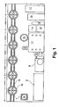
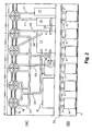
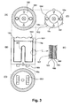
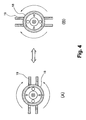
- FIG. 1 The outline of an example treating line and incidental equipment of the recycling system according to this embodiment of the invention is shown in Fig. 1 , the outline of a conduit arrangement is shown in Fig. 2 , an example structure of a container is shown in Fig. 3 , and a method of removing the container from the treatment line is shown in Fig. 4 .
- This system does not comprise a furnace, but does include a container 18, which is transportable and provided with a heater, as a basic unit along the treating line.
- the recycling process performed by the system according to this example is a process to treat multiple containers 18 in parallel by passing the containers 18 in order of steps 1 to 6 as shown in Fig. 1 and Fig. 2 .
- step 1 corresponds to the above-described first step
- steps 2 to 5 correspond to the above-described second step
- step 6 corresponds to the above-described third step.
- nitrogen pipes 21 correspond to the above-described first pipeline
- an oxygen/moisture conduit 22 correspond to the above-described first pipeline
- an oxygen/moisture conduit 22 correspond to the above-described first pipeline
- an oxygen/moisture conduit 22 correspond to the above-described first pipeline
- an oxygen/moisture conduit 22 correspond to the above-described first pipeline
- an oxygen/moisture conduit 22 correspond to the above-described first pipeline
- an oxygen/moisture conduit 22 correspond to the above-described chlorine/miscellaneous gas conduit 23
- miscellaneous gas pipes 24 correspond to the second pipeline.
- the individual pipelines are separately disposed according to gas type such that gas supply/recovery can be performed separately according to gas type, and such that the gas in each pipeline does not come into contact with the outside air.
- waste containing water, chlorine, and high-molecular compounds other than carbon and metal correspond to the above-described object to be treated
- a substance group extracted through the pipeline in steps 2 to 5 corresponds to the above-described first product
- a substance group remaining in the container 18 after step 6 is completed corresponds to the above-described second product.
- the container 18 is comprised of a cylindrical bottomed box container body 181 and a lid 182 as shown in Fig. 3 .
- the top of the container body 181 has an opening for inserting the object waste into the container 18 and for removing the second product from the container 18.
- the lid 182 is also used to close the opening and provide the container 18 with an airtight seal.
- wheels 183 are disposed as transport assisting members on the bottom face of the container body 181 to make the container 18 transportable. The wheels 183 can be used to move the container 18 along a track 19 shown in Fig. 1 and Fig.
- the wheels 183 are, of course, just one example of transport assisting structures that can be provided to ease movement of the container 18.
- handles or races may be disposed instead of or together with the wheels 183 to perform the same function.
- the container 18 can be configured to have a flat bottom surface so that it may be conveyed by a conveyor belt.
- the container body may have a form other than a cylindrical bottomed box type as suits the waste to be treated.
- the container body may have a rectangular bottomed box shape with a side-opening lid.
- the rectangular bottomed box container body with a side-opening lid has an advantage that the container can be inserted with waste by working on the container rails without lifting.
- a heater 185 is incorporated into the side wall, bottom, and a pole 184 installed upright on the bottom of the container body 181.
- An example of a heater built into the side wall is shown in Fig. 3(E) .
- the container body 181 has a structure in which the heater 185, which may be, for example, an infrared carbon ceramic heater or a carbon filament heater, is mounted on the inside surface of a metallic member 186 made of iron or a similar metal.
- a protective net 187 prevents the heater 185 from falling by pressing the heater 185 against the inside surface of the metallic member 186.
- the protective net 187 can also prevent the heater 185 from being soiled by direct contact with the object.
- an insulating material 189 is disposed between the outside surface of the metallic member 186 and an externally positioned exterior material 188.
- a plurality of poles 184 may be provided in appropriate numbers and positions considering the volume of the container body 181 and the like, to ensure uniform heating of all contents of the container body 181.
- Wiring for supplying the heater 185 with power is not shown because appropriate wiring can be designed by an engineer or one skilled in the art according to the disclosure of the present application.
- the heater 185 is not limited to configurations in which it is disposed along the entire wall surface and the overall height.
- an upper limit line of the filled amount of the object may be set slightly above the top of the pole-184 and slightly below the bottom surface of the lid 182, and the heater 185 maybe disposed just below the line.
- 18a indicates a power switch for the heater 185, which may be, for example, incorporated into the container body 181 to activate the supply of electricity to the heater 185 when the container 18 reaches a prescribed position on the track 19.
- the lid 182 is attached to the opening of the container body 181 to separate the contents of the container 18 from the outside air while performing the steps 1 to 6 shown in Fig. 1 and Fig. 2 .
- the lid 182 is designed to have dimensions matching the dimensions of the opening of the container body 181 so that the container 18 will have an airtight seal when the lid 182 is fitted to the top opening of the container body 181.
- a small number (three in the drawing) of projections are formed on the edge of the lid 182 as fixing parts 18b for fixing the lid 182 to the opening of the container body 181.
- the fixing parts 18b engage with recesses formed in the inside wall of the opening of the container 181 to fix the lid 182 to the container body 181 as shown in Fig. 3(B) .
- a small number (two in the drawing) handles 18c are formed on the top surface of the lid 182 so that the lid 182 can be detached from the container body 181, either manually or by use of a lid fitting device 7 of Fig. 1 .
- the lid 182 In the lid 182 is also formed an inlet 18d for introducing nitrogen into the container 18 when it is in a sealed state and an outlet 18e for discharging gases discharged from the contents during heating and the atmosphere expelled from the airtight container 18 by the introduction of nitrogen.
- the inlet 18d and the outlet 18e may alternatively be formed in the container body 181.
- the first and second pipelines are respectively connected to the inlet 18d and the outlet 18e.
- the inlet 18d and the outlet 18e are provided with an appropriate lid or valve (each pipeline is also provided with a lid or a valve in the same manner), so that, when the container 18 is moved from one step to the next step, it is possible to maintain the container 18 in a sealed state even when the pipelines are disconnected from the container 18, to thereby prevent air from entering the container 18 and to prevent gas, such as chlorine, from leaking from the container 18 when the container 18 is separated from the pipelines.
- the lid 182 may also be provided with a microwave generator which can be used for dehydration or the like of raw waste or the like in step 2 and an auxiliary machine mounting section 18f for mounting various types of electrical auxiliary machines.
- Sensors or probes such as a temperature sensor and a pressure sensor, used to control heating by the heater 185 and to control the individual steps can also be incorporated into the lid 182 or the individual pipelines.
- Wiring for control such as wiring within and around the container 182 and also wiring relevant to an electrical control panel 8 to be described later are not shown. Such wiring can be designed by any engineer or anyone skilled in the art according to the disclosure of the present application.
- the bottom face of the lid 182 is provided with a filter 18g to prevent an unnecessary matter from adhering to the sensors/probes and the unnecessary matter from being discharged through the outlet 18e or the like as shown in Fig. 3 (B) .
- Step 1 is a step to replace the atmosphere in the container 18 with an oxygen-free atmosphere by injecting nitrogen into the container. This process is performed in a state with the heater 185 off, in other words, in a state wherein the temperature within the container 18 is room temperature or a normal temperature.
- the nitrogen conduit 21 is connected to the inlet 18d of the airtight container 18 in which waste has been place, and the oxygen/vapor conduit 22 is connected to the outlet 18e, so that there is no connection with the air outside of the container 18.
- a nitrogen gas generating device 9 is a device to generate nitrogen under control by the electrical control panel 8 and is provided with a compressor 10 for compressing the gas.
- the nitrogen gas generating device 9 extracts nitrogen from the compressed air and delivers it to the nitrogen conduit 21.
- nitrogen is advantageous because it can be produced at a low cost by extraction from the atmosphere, and because it causes relatively very little damage.
- Nitrogen delivered into the nitrogen conduit 21 enters the container 18 through the inlet 18d.
- the existing gas, e.g., the air, contained in the container 18 is expelled from the container 18 through the outlet 18e and delivered to the oxygen/vapor conduit 22. Step 1 is continued until the concentration of oxygen in the container 18 falls below a prescribed concentration, or until after elapse of an amount of time sufficient to accomplish such a drop in oxygen concentration.
- step 1 the nitrogen conduit 21 is separated from the inlet 18d, and the oxygen/vapor conduit 22 is separated from the outlet 18e.
- the inlet 18d and the outlet 18e are closed to maintain the airtight state of the container 18, as described above, until they are connected again to the pipelines in step 2. The same process is also applied when the container is moved between other steps.
- the container body 181 Before injection of nitrogen is started, it is necessary to insert the object waste into the container body 181, place the container 18 on the track 19 so that it can be moved to the implementation position of step 1, and to seal the container 18 by fitting the lid 182 to the opening of the container body 181.
- the order and details of the operations can be determined as required. For example, a procedure in which an empty container 18 which is covered with the lid 182 is brought in, the lid 182 is removed to fill the container, and the lid 182 is then replaced may be performed. Alternatively, a procedure in which the container body 181 is first provided without the lid 182, and the container is sealed with lid 182 after the container has been filled with waste may be employed.
- the container body 181 already filled with waste may be provided such that only installation of the lid 182 is required may also be used.
- the operations to fill the container and seal it with the lid 182 can be performed in an ordinary atmosphere, or a method by which the air is discharged from the container 18 to depressurize it and nitrogen is introduced into the container 18 can also be employed.
- the lid mounting device 7 of Fig. 1 is a device for attaching and removing the lid 182 on the track 19 in response to an operation. It is desirable to provide a crushing machine or the like (not shown) for use when the object waste is excessively large in comparison with the size of the container 18.
- step 1 The container 18 having its inside atmosphere replaced with an oxygen-free atmosphere step 1 is moved to the implementation position of step 2.
- the nitrogen conduit 21 is connected to the inlet 18d
- the oxygen/vapor conduit 22 is connected to the outlet 18e
- the heater 185 is turned on.
- the supply of electricity to the heater 185 in step 2 is controlled so as to provide a temperature of 150°Cfor a period of time sufficient to substantially complete extraction of the water content of the waste.
- This control may be made autonomously in the container 18 while receiving feedback from the temperature sensor within the container 18, or while sequentially monitoring output of the temperature sensor by the electrical control panel 8.
- the object is heated to the boiling point of water in the container 18 to vaporize the water content from the waste.
- a microwave generator or the like may be incorporated into the auxiliary machine mounting section 18f for use in conjunction with the heater 185 so as to promote the vaporization of water.
- the vaporized water content namely water vapor liberated from the object, is expelled into the oxygen/vapor conduit 22 as the inside pressure of the container 18 increases with the vaporization or as nitrogen is introduced through the nitrogen conduit 21. Therefore, gas containing the water content, oxygen, nitrogen and the like is delivered to the oxygen/vapor conduit 22.
- This gas has the same components as the normal atmosphere, but with the ratio of nitrogen increased and an increased water content. As such, emission to the atmosphere of this untreated gas has no negative effect on the environment.
- the recovered gas contains recyclable components as well as usable heat
- a gas cooling device 11 used as a heat exchanger.
- 12 is a water tank belonging to the heat exchanger
- 13 is a cooling tower.
- step 3 to liberate chlorine for extraction.
- the container 18 is moved to the implementation position of step 3, the nitrogen conduit 21 is connected to the inlet 18d, and the chlorine/miscellaneous gas conduit 23 is connected to the outlet 18e.
- the heating temperature is controlled to a temperature of about 200 °C to 350°C, the temperature at which chlorine is vaporized and liberated from the object but high-molecular gas is not decomposed by heat, using the heater 185, and this temperature is maintained until all or substantially all chlorine has been extracted.
- the container 18 has an oxygen-free atmosphere and no internal combustion, and the chlorine/miscellaneous gas conduit 23 is not open to the atmosphere, harmful dioxins and the like are not produced from the liberated chlorine.
- Gas which contains chlorine and various miscellaneous gases liberated from the waste is delivered to the chlorine/miscellaneous gas conduit 23 and recovered and cooled by the gas cooling device 11.
- the resulting liquid e.g., chlorine ion water
- Gas which could not be liquefied by the gas cooling device 11, is neutralized by, for example, a demineralizer 11b using sodium hydroxide so to convert to a liquid mainly containing salt water.
- a very small amount of gas (e.g., ethanol-based gas usually existing in the natural world) is rendered harmless by means of a neutralizing machine using slaked lime or the like.
- a device for separating components according to mass differences may also be used as the demineralizer.
- Gas having passed through the demineralizer 11b e.g., miscellaneous gas, can be compressed using, for example, a compressor 14, and stored in a cylinder 15.
- the miscellaneous gas does not contain chlorine, and no dioxins will be produced, even if it the gas is burned by a burner or the like.
- Step 3 is followed by step 4 for extracting hydrocarbon-based high-molecular compounds by vaporizing and liberating.
- the nitrogen conduit 21 is connected to the inlet 18d of the container 18 which is moved to the implementation position of step 4 and the miscellaneous gas conduit 24 is connected to the outlet 18e.
- the temperature within the container is controlled to a temperature at which component high-molecular gases are liberated from the object, specifically about 350°C to 450°C, and this temperature is maintained long enough for substantially complete extraction of the high-molecular gas. Because the container 18 has an oxygen-free atmosphere and no internal combustion in it, and the miscellaneous gas conduit 24 is not open to the atmosphere, carbon dioxide, etc. are not generated from the liberated high-molecular gas.
- the gas containing the high-molecular gas liberated from the object in addition to nitrogen is delivered into the miscellaneous gas conduit 24 and recovered by the gas cooling device 11.
- the gas cooling device 11 cools the recovered gas independent of the gas recovered in other steps to obtain naphtha, which is equivalent to Heavy fuel oil A.
- Step 4 is followed by step 5 for adhering carbon.
- the nitrogen conduit 21 is connected to the inlet 18d of the container 18 which is moved to the implementation position of step 5 and the miscellaneous gas conduit 24 is connected to the outlet 18e.
- the temperature is maintained at about 450°C for a period of time sufficient for the adherence of carbon.
- carbon dioxide and the like are not produced for the same reason as in the above description regarding step 4.
- the high-molecular gas recovered in this step is treated in the same manner as the high-molecular gas recovered in step 4.
- Step 5 is followed by step 6 for cooling the product remaining in the container 18 after the treatment.
- a nitrogen conduit 21 from a nitrogen transport machine 16 is connected to the inlet 18d of the container 18 which is moved to the implementation position of step 6, the nitrogen conduit 21 from a cooling liquid nitrogen tank 17 is connected to the outlet 18e, and the heater 185 is turned off.
- the inside of the container is cooled down to a temperature lower than the temperature at which carbon begins to burn by introducing low-temperature nitrogen gas from the cooling liquid nitrogen tank 17.
- the temperature inside the container has cooled down to, for example, approximately 50°C to 100°C, carbon in the container does not rapidly oxidize, even when the lid 182 is opened to expose the contents to the atmosphere.
- the product remaining in the container 18 when step 6 is completed contains carbon which is not oxidized and metal with unchanged properties and can therefore be reusedin its form at that time or recycled by a relatively simple additional treatment. It is also possible to separate and extract desired metal from the product remaining in the container using mass differences to sort the materials.
- the nitrogen used in this step can also be transported by the nitrogen transport machine 16 for reuse to the gas cooling device 11 through a nitrogen recycling conduit 25. Nitrogen gas may be introduced from the nitrogen gas generating device 9, which may replace the use of liquid nitrogen. Otherwise, the container 18 may be left standing sealed in an airtight state. The inside of the container 18 can be cooled down by simply leaving it for a sufficient time. Exposure to normal temperature is preferable for reducing the thermal stress applied to the container 18.
- the treatment is performed by a thermal decomposition process not involving combustion, so that reusable carbon can be obtained at the end of step 6 without producing carbon dioxide or sulfur oxide.
- heating is performed in an oxygen-free atmosphere and the temperature in the container 18 is not raised beyond approximately 450°C, the metal components in the object waste are not oxidized nor are their properties altered. These metals remain in the container 18 in a reusable state, and no heavy metals are dissipated. Further, no dioxins are produced because the object waste is exposed to temperatures sufficiently high to liberate chlorine and high-molecular compounds.
- the amount of residual dioxins was 10 -3 ng-TEQ/g (TEQ: toxicity equivalence quantity) or less, an amount which is substantially equal to zero. Because the temperature in the container 18 is merely raised to approximately 450°C, nitrogen oxide is net produced, regardless of heating in the atmosphere mainly containing nitrogen. Soot is not emitted because the object in the container is not burnt or stirred, and gases such as chlorine, high-molecular compounds, and the like produced in the treating process can be liquefied by the gas cooling device 11 for recycling. Most of the object waste is recycled, and the reclamation disposal or the like of the residue can be substantially eliminated.
- TEQ toxicity equivalence quantity
- the container 18 having the heater 185 is transportable, it is not necessary to install, maintain, or operate a furnace, and energy required for the treatment is reduced. As a result, advantageous effects such as reductions in the scale of equipment, installation space requirements, cost, and labor can all be obtained simultaneous with improvements in the efficient of recycling. For example, when the system is configured using the containers 18 having an inner diameter of approximately 500 mm, the amount of space required is only approximately 6m ⁇ 2m, even when a relatively large interval I set between the adjacent containers. When the containers 18 have such dimensions, a relatively low power heater 185 can be used to heat the object waste to the target temperatures.
- the implementation location is divided into areas for individual steps, and pipelines are separately disposed for the individual implementation places as shown in Fig. 1 and Fig. 2 .
- the number of pipeline connection ports (the inlet 18d and the outlet 18e in the above description) formed in the container 18 can be reduced, and the container 18 can be configured to be compact, simple, and low cost. Because the container 18 is moved from one step location to another, as in an assembly line, to perform a. series of steps, a plurality of containers 18 can be treated simultaneously, and a waste treatment efficiency can be increased.
- the present invention can be performed by determining a common location for the implementation of the first and second steps. This makes it possible to conduct the individual steps without moving the container, and all pipelines required for the first and second steps can be provided at one location. In a preferred embodiment of the present invention, it is necessary to measure a number of values, which complicates the configuration of the container and arrangement of the pipelines and conduits. Multiple pipeline connection ports may be provided in the container so that different ports are used for each step or each type of gas, or a valve may be formed on the side of the conduit arrangement so that a pipeline may be used in common, in multiple steps. This configuration realizes additional advantages in that it is not necessary to move the container, the space occupied by the treatment line can be reduced, and the like.
- FIG. 5 is an explanatory view showing a configuration of a carbon material manufacturing system according to an example of the embodiment of the invention, and particularly the outline of a treatment line and its incidental equipment.
- Each of the steps 1 to 6 is performed in substantially the same manner as the steps shown in Fig. 1 and Fig. 2 , and the same reference numerals are given to the components of Fig. 5 which are identical to those shown in Figs. 1 to Fig. 3 .
- a high-molecular compound which is an object 27 to be treated is put on a belt conveyor and conveyed to a container filling device 29.
- the container filling device 29 opens a square bottomed box container 18 with a side-opening lid to insert the object into it and closes the lid to seal the container 18.
- the container 18 is a side-opening lid type to allow inserting and discharging of the object 27 from the side of the container.
- Other configurations of forming the nitrogen gas inlet 18d and the gas outlet 18e on the top and having the heater 185 built in the inside wall are the same as those of the circular bottomed container 181 described above.
- the container 18 in which the object 27 is filled is moved to the first step along the track 19 for transporting the container 18.
- step 1 the inside of the container 18 is filled with a nitrogen atmosphere.
- the nitrogen conduit 21 is connected to the inlet 18d, and the oxygen/vapor conduit 22 is connected to the outlet 18e.
- Nitrogen from the nitrogen generating device 9 is introduced into the container 18 through the inlet 18d via the nitrogen conduit 21.
- air oxygen
- the oxygen is discharged to the oxygen/vapor conduit 22 through the outlet 18e.
- the oxygen is removed, and the container 18 is filled with an oxygen-free nitrogen atmosphere.
- the container 18 filled with the nitrogen atmosphere is moved to a second step for drying.
- the nitrogen conduit 21 is connected to the inlet 18d, and the oxygen/vapor conduit 22 is connected to the outlet 18e.
- the built-in heater 185 is turned on to heat the insider of the container to approximately 150°C. This temperature is maintained until the container inside and the object 27 become dry.
- the container 18, the insider of which was dried in step 2 is then moved to step 3 for liberating and extracting chlorine and step 4 for liberating and extracting a high-molecular compound.
- step 3 for liberating and extracting chlorine
- step 4 for liberating and extracting a high-molecular compound.
- This is accomplished by moving the container 18 to the implementation locations of steps 3 and 4, where the nitrogen conduit 21 is connected to the inlet 18d and the chlorine/miscellaneous gas conduit 23 is connected to the outlet 18e.
- the container 18 may be moved, but in the present example the operations of both steps are performed at the same location. Thus, the operation to move the container between steps 3 and 4 can be omitted.
- step 3 the heater is controlled to maintain a heating temperature in a range of 200°C to 350°C in order that the chlorine is vaporized and liberated from the object, but that high-molecular gas is not decomposed by heat. This temperature is maintained for a length of time sufficient for substantially complete extraction of chlorine. No dioxins are produced from the liberated chlorine because the container 18 has an oxygen-free atmosphere, there is no combustion, and the-chlorine/miscellaneous gas conduit 23 is not open to the atmosphere.
- Step 3 is followed by step 4.
- Control is performed such that the nitrogen conduit 21 is kept connected to the inlet 18d of the container 18 and the miscellaneous gas conduit 24 is kept connected to the outlet 18e as in step 3, the heating temperature by the heater 185 is a temperature, specifically 350°C to 450°C, at which high-molecular gases are liberated from the object, and the temperature is maintained for a time sufficient for substantially complete extraction of the high-molecular gases.
- Carbon dioxide or the like is not produced from the liberated high-molecular gases because the container 18 has an oxygen-free atmosphere, combustion is not caused, and the miscellaneous gas conduit 24 is not open to the atmosphere.
- Steps 3 and 4 are followed by step 5 for adhering carbon.
- the nitrogen conduit 21 is connected to the inlet 18d of the container 18 which is moved to the implementation place of step 5, and the miscellaneous gas conduit 24 is connected to the outlet 18e.
- the heater 185 is controlled so that the temperature remains within a range of 450°C to 500°C for a length of time sufficient to adhere carbon. At such a temperature, the object 27 has a high adhesion rate of carbon to provide inert carbon of superior quality. If the temperature becomes higher than that level, the carbon will have a small volume and may become stiff.Because this system operates in a nitrogen atmosphere or oxygen-free atmosphere, inert carbon can be obtained efficiently without an intermediate stage of activated carbon as a carbon material.
- Step 5 is followed by step 6 for cooling the product remaining in the container 18.
- the heater 185 is turned off.
- step 6 the container 18 is kept in a. state isolated from the air and has the oxygen-free atmosphere in it, and low-temperature nitrogen gas is introduced from a cooling liquid nitrogen tank (not shown) to cool the container to a temperature lower than that at which carbon will burn.
- a cooling liquid nitrogen tank not shown
- the lid of the container 18 can be opened without oxidizing the carbon in the container.
- inert carbon (second product) 33 is obtained as a residue of the object 27
- the container 18 containing the inert carbon 33 is moved to an acquisition device 31.
- the acquisition device 31 opens the lid of the container 18, retrieves the inert carbon 33, which is a residue of the object 27, from inside the container interior, and places the obtained inert carbon 33 on the conveyor belt at the exit.
- the container 18, which is now empty because the inert carbon 33 was removed, is put on the track 19 and again moved to the container filling device 29 to allow inserting a fresh object 27.
- the charged container 18 repeats the above-described steps and is refilled with an object by the container inserting device 29.
- the obtained inert carbon can be treated by an inert carbon treating device 35 to produce activated carbon, carbon nanotubes, and other various carbon materials.
- an activation treating device may be used as the inert carbon treating device 35 to treat the activated carbon.
- the inert carbon 33 removed from the acquisition device 31 by the belt conveyor is conveyed into the activation treating device.35.
- the inert carbon 33 placed in the-activation treating device 35 can be activated with high-temperature vapor gas to obtain activated carbon.
- a carbon nanotube manufacturing device is used as the inert carbon treating device 35 to produce carbon nanotubes as a carbon material.
- the manufacturing device may be a device capable of producing carbon nanotubes from the inert carbon, for example, a device using an arc discharge method, a laser vaporization method, a steam-activation method or the like, but such a device is not exclusive.
- a method of producing carbon nanotubes using a carbon nanotube manufacturing device using an arc discharge method as the inert carbon treating device will be described.
- the inside of the carbon nanotube manufacturing device is filled with an inert gas, preferably helium.
- the inert carbon 33 removed by the conveyor belt from the acquisition device 31 of Fig. 5 is conveyed into the carbon nanotube manufacturing device used as the inert carbon treating device 35.
- the inert carbon 33 is set as the anode in the carbon nanotube manufacturing device.
- a current of approximately 100A is passed between the inert carbon 3 and the cathode to cause an arc discharge.
- the inert carbon 33 as the anode is evaporated as carbon vapor by the arc discharge.
- the carbon vapor is directly condensed at the leading end of the cathode to become carbon nanotubes.
- carbon nanotubes are produced.
- the produced carbon nanotubes are often multilayer carbon nanotubes, but it is also possible to produce single-layer carbon nanotubes by including catalytic metals (e.g., Fe, Ni, Co, Y or La and its alloy) in the inert carbon 33 set as the anode.
- the incorporation of the inert carbon treating device 35 into the present invention enables low-cost production of large quantities of high-quality activated carbon or carbon nanotubes.
- the recycling method and system according to the present invention can efficiently perform low-cost recycling of wastes such as high-molecular compounds using small-scale equipment and without creating unnecessary or toxic waste.
- wastes such as high-molecular compounds
- production of carbon dioxide, dioxin, or oxidized compounds during the treatment can be prevented, as can the corresponding environmental (air, soil, water, etc.) pollution.
- the present invention can realize contributions to society and the environment in addition to industrial applicability.
- the carbon material manufacturing method and system of the invention can recycle high-molecular compounds to effectively produce inert carbon from the high-molecular compounds.
- the carbon material manufacturing method and system of the present invention can recycle high-molecular compounds to produce inert carbon and can also produce from the produced inert carbon useful carbon materials such as carbon nanotubes and activated carbon in a large amount at a low cost by continuous production. Creation of a new industry can be expected based on the above large-scale, low-cost productivity. Use of carbon nanotubes, which were heretofore expensive and not commonly used in ordinary-commodities, can be promoted, and their physical properties-such as lightweight and high strength can be easily utilized for producing and enhancing those commodities.
- the container of the invention is easily handled when used for either the recycling method and system or the carbon material manufacturing method and system described above.
Landscapes
- Chemical & Material Sciences (AREA)
- Engineering & Computer Science (AREA)
- Oil, Petroleum & Natural Gas (AREA)
- Organic Chemistry (AREA)
- Materials Engineering (AREA)
- Nanotechnology (AREA)
- Physics & Mathematics (AREA)
- General Physics & Mathematics (AREA)
- Crystallography & Structural Chemistry (AREA)
- Condensed Matter Physics & Semiconductors (AREA)
- Inorganic Chemistry (AREA)
- General Chemical & Material Sciences (AREA)
- Life Sciences & Earth Sciences (AREA)
- Wood Science & Technology (AREA)
- Chemical Kinetics & Catalysis (AREA)
- Manufacturing & Machinery (AREA)
- Combustion & Propulsion (AREA)
- Composite Materials (AREA)
- Environmental & Geological Engineering (AREA)
- Processing Of Solid Wastes (AREA)
- Carbon And Carbon Compounds (AREA)
- Separation, Recovery Or Treatment Of Waste Materials Containing Plastics (AREA)
- Supplying Of Containers To The Packaging Station (AREA)
Claims (12)
- Procédé de recyclage, comprenant :une première étape consistant à remplacer l'atmosphère dans un récipient (18) contenant un objet à traiter, par une atmosphère dépourvue d'oxygène ;une deuxième étape consistant à chauffer l'objet dans le récipient à une température prédéterminée en utilisant un dispositif de chauffage (185) préinstallé dans le récipient tout en maintenant l'atmosphère dépourvue d'oxygène dans le récipient afin de libérer un gaz spécifique de l'objet, et guider le gaz libéré en tant que premier produit jusqu'à un dispositif extérieur du récipient tout en maintenant le premier produit dans un état isolé de l'air afin d'obtenir le premier produit dans un état fluide ; etune troisième étape consistant à refroidir l'intérieur du récipient jusqu'à une température inférieure à la température à laquelle le carbone brûle tout en maintenant de manière continue l'atmosphère dépourvue d'oxygène dans le récipient et obtenir un résidu restant dans le récipient en tant que deuxième produit.
- Procédé de recyclage selon la revendication 1, dans lequel :la deuxième étape est réalisée deux fois ou plus;une température de chauffage de l'objet dans chacune de la pluralité des deuxièmes étapes est déterminée de sorte que la température de chauffage dans une étape suivante est supérieure à celle de la deuxième étape précédente, et selon le gaz à libérer en tant que premier produit dans cette étape; etun acheminement de guidage et une destination guidée pour l'acquisition du premier produit sont déterminés séparément pour chacune de la pluralité des deuxièmes étapes.
- Procédé de recyclage selon la revendication 1, dans lequel la deuxième étape est l'une quelconque parmi une étape consistant à obtenir de l'eau en tant que premier produit, une étape consistant à obtenir un fluide contenant du chlore en tant que premier produit, et une étape consistant à obtenir un gaz à poids moléculaire élevé ou un fluide produit à partir du gaz à poids moléculaire élevé en tant que premier produit.
- Procédé de recyclage selon la revendication 1, dans lequel :la première étape est réalisée avec un premier dispositif pour alimenter au moins un gaz de réduction ou un gaz inerte raccordé au récipient par une première conduite ;la deuxième étape est réalisée avec le premier dispositif raccordé au récipient par la première conduite et un deuxième dispositif en tant que dispositif extérieur du récipient raccordé au récipient par une deuxième conduite ; etle récipient est placé dans un état étanche lorsqu'il faut déconnecter la conduite entre le récipient et le premier ou deuxième dispositif afin de déplacer le récipient d'une étape à l'étape suivante.
- Procédé de recyclage selon la revendication 4, dans lequel un emplacement de mise en oeuvre différent est déterminé pour chaque étape, et une conduite requise pour la mise en oeuvre de chaque étape aux emplacements de mise en oeuvre individuels est étendue jusqu'à l'emplacement de mise en oeuvre afin de permettre le traitement simultané d'une pluralité de récipients selon un procédé de chaîne d'assemblage en déplaçant en séquence les récipients d'une étape à l'étape suivante.
- Procédé de recyclage selon la revendication 4, dans lequel les emplacements de mise en oeuvre d'au moins les première et deuxième étapes sont conçus pour être un emplacement commun afin de permettre de réaliser au moins les première et deuxième étapes sans déplacer le récipient, et toutes les conduites nécessaires pour les première et deuxième étapes sont étendues jusqu'audit emplacement commun.
- Système de recyclage, comprenant :des moyens de conversion pour remplacer l'atmosphère dans un récipient contenant un objet à traiter, par une atmosphère dépourvue d'oxygène ;des premiers moyens d'obtention de produit pour chauffer le produit dans le récipient jusqu'à une température prédéterminée en utilisant un dispositif de chauffage installé dans le récipient tout en maintenant l'atmosphère dépourvue d'oxygène dans le récipient afin de libérer un gaz prédéterminé de l'objet et guider le gaz libéré, en tant que premier produit jusqu'à un dispositif externe du récipient tout en maintenant le gaz libéré dans un état isolé de l'air afin d'obtenir le premier produit dans un état fluide ; etdes deuxièmes moyens d'obtention de produit pour refroidir l'intérieur du récipient jusqu'à une température inférieure à la température à laquelle le carbone brûle tout en maintenant de manière continue l'atmosphère dépourvue d'oxygène dans le récipient et obtenir un résidu restant dans le récipient en tant que deuxième produit.
- Système de recyclage selon la revendication 7, dans lequel :les moyens de conversion sont des moyens pour convertir l'atmosphère dans le récipient en une atmosphère dépourvue d'oxygène en utilisant un premier dispositif pour alimenter au moins un gaz de réduction ou un gaz inerte raccordé au récipient par une première conduite ;les premiers moyens d'obtention de produit sont des moyens pour obtenir le premier produit par le deuxième dispositif avec le premier dispositif raccordé au récipient par la première conduite et le deuxième dispositif en tant que dispositif extérieur du récipient raccordé au récipient par une deuxième conduite ; etle récipient est placé dans un état étanche lorsque la conduite entre le récipient et le premier ou deuxième dispositif est déconnectée.
- Procédé de fabrication d'un matériau en carbone comprenant:une première étape consistant à remplacer l'atmosphère dans un récipient contenant un composé à poids moléculaire élevé, par une atmosphère dépourvue d'oxygène ;une deuxième étape consistant à chauffer un objet à traiter dans le récipient jusqu'à une température prédéterminée en utilisant un dispositif de chauffage installé dans le récipient tout en maintenant l'atmosphère dépourvue d'oxygène dans le récipient afin de libérer un gaz prédéterminé de l'objet et guider le gaz libéré en tant que premier produit jusqu'à un dispositif extérieur du récipient tout en maintenant le gaz libéré dans un état isolé de l'air afin d'obtenir le premier produit dans un état fluide ; etune troisième étape consistant à refroidir l'intérieur du récipient jusqu'à une température inférieure à la température à laquelle le carbone brûle tout en maintenant de manière continue l'atmosphère dépourvue d'oxygène dans le récipient et obtenir le carbone inerte en tant que deuxième produit qui est un résidu restant dans le récipient.
- Procédé de fabrication d'un matériau en carbone selon la revendication 9, dans lequel des nanotubes de carbone sont produits à partir du carbone inerte obtenu à la troisième étape.
- Procédé de fabrication d'un matériau en carbone selon la revendication 9, dans lequel le charbon actif est produit à partir du carbone inerte obtenu à la troisième étape.
- Récipient utilisé pour réaliser un procédé de recyclage, dans lequel :le récipient est formé pour avoir une ouverture recouverte à travers laquelle on peut insérer un objet à traiter et à travers laquelle on peut récupérer un deuxième produit, une entrée à laquelle une première conduite est raccordée, et une sortie à laquelle une deuxième conduite est raccordée, et en outre prévu avec :une structure d'assistance de transport destinée à être utilisée lors du déplacement du récipient, etun dispositif de chauffage installé à l'intérieur du récipient pour chauffer l'objet dans le récipient.
Applications Claiming Priority (3)
| Application Number | Priority Date | Filing Date | Title |
|---|---|---|---|
| JP2002217136 | 2002-07-25 | ||
| JP2002217136 | 2002-07-25 | ||
| PCT/JP2003/008028 WO2004011165A1 (fr) | 2002-07-25 | 2003-06-25 | Procede, systeme et conteneur pour recycler des ressources |
Publications (4)
| Publication Number | Publication Date |
|---|---|
| EP1522355A1 EP1522355A1 (fr) | 2005-04-13 |
| EP1522355A4 EP1522355A4 (fr) | 2005-12-07 |
| EP1522355B1 true EP1522355B1 (fr) | 2011-11-30 |
| EP1522355B9 EP1522355B9 (fr) | 2012-02-29 |
Family
ID=31184596
Family Applications (1)
| Application Number | Title | Priority Date | Filing Date |
|---|---|---|---|
| EP03736245A Expired - Lifetime EP1522355B9 (fr) | 2002-07-25 | 2003-06-25 | Procede, systeme et conteneur pour recycler des ressources |
Country Status (12)
| Country | Link |
|---|---|
| US (1) | US7604791B2 (fr) |
| EP (1) | EP1522355B9 (fr) |
| JP (1) | JP4047331B2 (fr) |
| KR (1) | KR100572241B1 (fr) |
| CN (1) | CN1253255C (fr) |
| AT (1) | ATE535321T1 (fr) |
| AU (1) | AU2003243971A1 (fr) |
| ES (1) | ES2378148T3 (fr) |
| HK (1) | HK1071866A1 (fr) |
| MY (1) | MY144391A (fr) |
| TW (1) | TWI230101B (fr) |
| WO (1) | WO2004011165A1 (fr) |
Families Citing this family (13)
| Publication number | Priority date | Publication date | Assignee | Title |
|---|---|---|---|---|
| KR100652474B1 (ko) | 2004-12-31 | 2006-12-01 | 한국전기연구원 | 폐타이어 재활용 장치 및 재활용 방법 |
| US20110052102A1 (en) * | 2005-09-19 | 2011-03-03 | Sven Stiers | Drain connector for substance processing receptacle |
| WO2007035592A2 (fr) * | 2005-09-19 | 2007-03-29 | Advanced Technology Materials, Inc. | Raccord d'ecoulement pour receptacle de traitement de substance |
| JP2007111603A (ja) * | 2005-10-19 | 2007-05-10 | Toshiba Corp | 廃棄物熱分解処理システムおよび方法 |
| EP2014729A1 (fr) | 2007-07-09 | 2009-01-14 | Sicpa Holding S.A. | Encre d'impression d' intaglio avec un agent de séchage contenant Vanadium |
| ITTO20070923A1 (it) * | 2007-12-20 | 2009-06-21 | Torino Politecnico | Procedimento di riciclo di materiali plastici di scarto con produzione di nanotubi di carbonio. |
| CN103703104A (zh) * | 2011-07-19 | 2014-04-02 | 株式会社万世 | 有机物碳化处理装置与碳化处理方法 |
| KR101176765B1 (ko) * | 2012-03-05 | 2012-08-28 | 유성종 | 폐기물 열처리 장치 |
| TW201341075A (zh) * | 2012-04-12 | 2013-10-16 | Gianhon Environmental Technology Co Ltd | 有機固體廢棄物快速資源化處理方法與設備 |
| WO2014008371A2 (fr) * | 2012-07-03 | 2014-01-09 | Plasmaten, Llc | Systèmes et procédés de conversion de matière organique en produits utiles |
| US9502723B2 (en) | 2013-11-22 | 2016-11-22 | Hamilton Sundstrand Corporation | Method of operating a fuel cell in confined space |
| JP2016155086A (ja) * | 2015-02-25 | 2016-09-01 | 農業生産法人株式会社 アグリジャパン | 再資源化設備 |
| CN109266365B (zh) * | 2018-09-05 | 2021-12-31 | 任慷平 | 成分分离式炭素化系统 |
Family Cites Families (13)
| Publication number | Priority date | Publication date | Assignee | Title |
|---|---|---|---|---|
| US5319176A (en) * | 1991-01-24 | 1994-06-07 | Ritchie G. Studer | Plasma arc decomposition of hazardous wastes into vitrified solids and non-hazardous gasses |
| US6172275B1 (en) * | 1991-12-20 | 2001-01-09 | Kabushiki Kaisha Toshiba | Method and apparatus for pyrolytically decomposing waste plastic |
| US5591312A (en) * | 1992-10-09 | 1997-01-07 | William Marsh Rice University | Process for making fullerene fibers |
| JP2651994B2 (ja) * | 1993-09-28 | 1997-09-10 | 株式会社會田金型製作所 | 廃タイヤから活性炭を製造する装置 |
| US5673635A (en) | 1995-06-12 | 1997-10-07 | L.E. Maxwitat | Process for the recycling of organic wastes |
| GB2303859A (en) | 1995-07-31 | 1997-03-05 | Combined Recycling & Power Ltd | Tyre pyrolysis method and apparatus |
| JP3405870B2 (ja) * | 1995-10-30 | 2003-05-12 | 株式会社デポ・ジャパン | 有機物炭化処理装置及び有機物炭化処理車両 |
| JPH101679A (ja) * | 1996-06-18 | 1998-01-06 | Masami Shibazuka | 有機廃棄物の炭化方法および炭化装置 |
| JP3946292B2 (ja) * | 1996-10-25 | 2007-07-18 | 株式会社ツシマ総業 | 炭素素材の製造装置 |
| JP3670469B2 (ja) | 1997-11-26 | 2005-07-13 | 株式会社東芝 | ポリ塩化ビニル含有廃プラスチック処理装置 |
| TW394749B (en) * | 1998-03-05 | 2000-06-21 | Deng Jian Lang | Method of manufacturing active carbon by using carbon black |
| JP2000319661A (ja) * | 1999-05-07 | 2000-11-21 | Sohachi Kosugi | 木と塩化ビニールの炭化方法及び装置 |
| US6244198B1 (en) | 1999-11-30 | 2001-06-12 | Bcde Group Waste Management Ltd., Oy | Method and equipment for pyrolytic treatment of organic material |
-
2003
- 2003-06-25 KR KR1020047007588A patent/KR100572241B1/ko not_active IP Right Cessation
- 2003-06-25 AT AT03736245T patent/ATE535321T1/de active
- 2003-06-25 ES ES03736245T patent/ES2378148T3/es not_active Expired - Lifetime
- 2003-06-25 CN CNB03801355XA patent/CN1253255C/zh not_active Expired - Fee Related
- 2003-06-25 EP EP03736245A patent/EP1522355B9/fr not_active Expired - Lifetime
- 2003-06-25 WO PCT/JP2003/008028 patent/WO2004011165A1/fr active IP Right Grant
- 2003-06-25 JP JP2004524102A patent/JP4047331B2/ja not_active Expired - Lifetime
- 2003-06-25 AU AU2003243971A patent/AU2003243971A1/en not_active Abandoned
- 2003-06-25 US US10/483,853 patent/US7604791B2/en not_active Expired - Fee Related
- 2003-07-14 TW TW092119119A patent/TWI230101B/zh not_active IP Right Cessation
- 2003-07-24 MY MYPI20032795A patent/MY144391A/en unknown
-
2005
- 2005-06-02 HK HK05104668A patent/HK1071866A1/xx not_active IP Right Cessation
Also Published As
| Publication number | Publication date |
|---|---|
| KR20040055809A (ko) | 2004-06-26 |
| CN1253255C (zh) | 2006-04-26 |
| MY144391A (en) | 2011-09-15 |
| TW200402335A (en) | 2004-02-16 |
| TWI230101B (en) | 2005-04-01 |
| JP4047331B2 (ja) | 2008-02-13 |
| US7604791B2 (en) | 2009-10-20 |
| EP1522355A1 (fr) | 2005-04-13 |
| EP1522355A4 (fr) | 2005-12-07 |
| US20040235655A1 (en) | 2004-11-25 |
| ES2378148T3 (es) | 2012-04-09 |
| HK1071866A1 (en) | 2005-08-05 |
| JPWO2004011165A1 (ja) | 2005-11-24 |
| CN1578706A (zh) | 2005-02-09 |
| EP1522355B9 (fr) | 2012-02-29 |
| WO2004011165A1 (fr) | 2004-02-05 |
| ATE535321T1 (de) | 2011-12-15 |
| KR100572241B1 (ko) | 2006-04-24 |
| AU2003243971A1 (en) | 2004-02-16 |
Similar Documents
| Publication | Publication Date | Title |
|---|---|---|
| US20090121798A1 (en) | High power microwave waste management | |
| EP1522355B1 (fr) | Procede, systeme et conteneur pour recycler des ressources | |
| US7832344B2 (en) | Method and apparatus of treating waste | |
| US8312821B2 (en) | Waste-tire recycling system | |
| US9599337B2 (en) | Method for treating solid waste based on a gradient composed of two distinct thermal sources | |
| US5245113A (en) | Decontamination of PCB contaminated solids | |
| KR20140016451A (ko) | 열분해장치 | |
| CN104907319A (zh) | 垃圾处理装置 | |
| CN113000557A (zh) | 布朗气热解危固废物处置技术系统及其应用方法 | |
| CN108800139B (zh) | 一种生活垃圾全自动化处理系统及方法 | |
| US20100043684A1 (en) | Refuse Processing and Energy Recovery System and Method | |
| CN213446975U (zh) | 一种垃圾碳化热解模块化处理设备 | |
| EP2132488A1 (fr) | Procédé pour l'élimination écologique de mélanges air/solvant avec une installation à piles à combustible et une unité de récupération | |
| JP5395062B2 (ja) | 廃棄物を予備加熱して廃棄物を焼却する方法及びプラント | |
| JP2007196229A (ja) | 処理装置 | |
| CN204799669U (zh) | 垃圾处理装置 | |
| JP2006336955A (ja) | 医療系廃棄物の処理方法およびその処理設備 | |
| KR101377425B1 (ko) | 폐 알루미늄 병뚜껑으로부터 알루미늄을 회수하기 위한 사전처리 장치 및 방법 | |
| RU2576711C1 (ru) | Устройство технологической линии утилизации твердых бытовых отходов с применением термической деструкции | |
| JP2007152350A (ja) | 処理装置及び処理方法 | |
| JP2001276791A (ja) | 廃棄物処理システム及び廃棄物処理方法 | |
| KR20220042858A (ko) | 열분해 기반의 친환경 폐기물 처리 장비 | |
| KR20230100352A (ko) | 과열 수증기를 이용한 탄화 장치 및 이를 이용한 열분해유 생산 방법 | |
| JP2003213033A (ja) | ゴム組成物の処理方法,処理装置,および処理システム | |
| CZ308259B6 (cs) | Zařízení pro termický rozklad a způsob provádění termického rozkladu |
Legal Events
| Date | Code | Title | Description |
|---|---|---|---|
| PUAI | Public reference made under article 153(3) epc to a published international application that has entered the european phase |
Free format text: ORIGINAL CODE: 0009012 |
|
| 17P | Request for examination filed |
Effective date: 20050125 |
|
| AK | Designated contracting states |
Kind code of ref document: A1 Designated state(s): AT BE BG CH CY CZ DE DK EE ES FI FR GB GR HU IE IT LI LU MC NL PT RO SE SI SK TR |
|
| AX | Request for extension of the european patent |
Extension state: AL LT LV MK |
|
| DAX | Request for extension of the european patent (deleted) | ||
| A4 | Supplementary search report drawn up and despatched |
Effective date: 20051025 |
|
| RIC1 | Information provided on ipc code assigned before grant |
Ipc: 7B 09B 3/00 A Ipc: 7C 10B 7/14 B Ipc: 7C 10B 53/00 B Ipc: 7C 10G 1/10 B |
|
| RIN1 | Information on inventor provided before grant (corrected) |
Inventor name: SATO, KUNIMICHI Inventor name: YANAGIHARA, MASAFUMI,C/O EEN CO., LTD. Inventor name: UENO, SYUJI,JAPAN RADIO CO., LTD. |
|
| GRAP | Despatch of communication of intention to grant a patent |
Free format text: ORIGINAL CODE: EPIDOSNIGR1 |
|
| GRAS | Grant fee paid |
Free format text: ORIGINAL CODE: EPIDOSNIGR3 |
|
| GRAA | (expected) grant |
Free format text: ORIGINAL CODE: 0009210 |
|
| AK | Designated contracting states |
Kind code of ref document: B1 Designated state(s): AT BE BG CH CY CZ DE DK EE ES FI FR GB GR HU IE IT LI LU MC NL PT RO SE SI SK TR |
|
| REG | Reference to a national code |
Ref country code: GB Ref legal event code: FG4D Ref country code: CH Ref legal event code: EP |
|
| REG | Reference to a national code |
Ref country code: IE Ref legal event code: FG4D |
|
| REG | Reference to a national code |
Ref country code: DE Ref legal event code: R096 Ref document number: 60339274 Country of ref document: DE Effective date: 20120209 |
|
| REG | Reference to a national code |
Ref country code: NL Ref legal event code: VDEP Effective date: 20111130 |
|
| REG | Reference to a national code |
Ref country code: ES Ref legal event code: FG2A Ref document number: 2378148 Country of ref document: ES Kind code of ref document: T3 Effective date: 20120409 |
|
| PG25 | Lapsed in a contracting state [announced via postgrant information from national office to epo] |
Ref country code: SE Free format text: LAPSE BECAUSE OF FAILURE TO SUBMIT A TRANSLATION OF THE DESCRIPTION OR TO PAY THE FEE WITHIN THE PRESCRIBED TIME-LIMIT Effective date: 20111130 Ref country code: NL Free format text: LAPSE BECAUSE OF FAILURE TO SUBMIT A TRANSLATION OF THE DESCRIPTION OR TO PAY THE FEE WITHIN THE PRESCRIBED TIME-LIMIT Effective date: 20111130 Ref country code: GR Free format text: LAPSE BECAUSE OF FAILURE TO SUBMIT A TRANSLATION OF THE DESCRIPTION OR TO PAY THE FEE WITHIN THE PRESCRIBED TIME-LIMIT Effective date: 20120301 Ref country code: PT Free format text: LAPSE BECAUSE OF FAILURE TO SUBMIT A TRANSLATION OF THE DESCRIPTION OR TO PAY THE FEE WITHIN THE PRESCRIBED TIME-LIMIT Effective date: 20120330 Ref country code: BE Free format text: LAPSE BECAUSE OF FAILURE TO SUBMIT A TRANSLATION OF THE DESCRIPTION OR TO PAY THE FEE WITHIN THE PRESCRIBED TIME-LIMIT Effective date: 20111130 Ref country code: SI Free format text: LAPSE BECAUSE OF FAILURE TO SUBMIT A TRANSLATION OF THE DESCRIPTION OR TO PAY THE FEE WITHIN THE PRESCRIBED TIME-LIMIT Effective date: 20111130 |
|
| PG25 | Lapsed in a contracting state [announced via postgrant information from national office to epo] |
Ref country code: CY Free format text: LAPSE BECAUSE OF FAILURE TO SUBMIT A TRANSLATION OF THE DESCRIPTION OR TO PAY THE FEE WITHIN THE PRESCRIBED TIME-LIMIT Effective date: 20111130 |
|
| PG25 | Lapsed in a contracting state [announced via postgrant information from national office to epo] |
Ref country code: DK Free format text: LAPSE BECAUSE OF FAILURE TO SUBMIT A TRANSLATION OF THE DESCRIPTION OR TO PAY THE FEE WITHIN THE PRESCRIBED TIME-LIMIT Effective date: 20111130 Ref country code: BG Free format text: LAPSE BECAUSE OF FAILURE TO SUBMIT A TRANSLATION OF THE DESCRIPTION OR TO PAY THE FEE WITHIN THE PRESCRIBED TIME-LIMIT Effective date: 20120229 Ref country code: SK Free format text: LAPSE BECAUSE OF FAILURE TO SUBMIT A TRANSLATION OF THE DESCRIPTION OR TO PAY THE FEE WITHIN THE PRESCRIBED TIME-LIMIT Effective date: 20111130 Ref country code: EE Free format text: LAPSE BECAUSE OF FAILURE TO SUBMIT A TRANSLATION OF THE DESCRIPTION OR TO PAY THE FEE WITHIN THE PRESCRIBED TIME-LIMIT Effective date: 20111130 Ref country code: CZ Free format text: LAPSE BECAUSE OF FAILURE TO SUBMIT A TRANSLATION OF THE DESCRIPTION OR TO PAY THE FEE WITHIN THE PRESCRIBED TIME-LIMIT Effective date: 20111130 |
|
| PG25 | Lapsed in a contracting state [announced via postgrant information from national office to epo] |
Ref country code: RO Free format text: LAPSE BECAUSE OF FAILURE TO SUBMIT A TRANSLATION OF THE DESCRIPTION OR TO PAY THE FEE WITHIN THE PRESCRIBED TIME-LIMIT Effective date: 20111130 |
|
| REG | Reference to a national code |
Ref country code: AT Ref legal event code: MK05 Ref document number: 535321 Country of ref document: AT Kind code of ref document: T Effective date: 20111130 |
|
| PLBE | No opposition filed within time limit |
Free format text: ORIGINAL CODE: 0009261 |
|
| STAA | Information on the status of an ep patent application or granted ep patent |
Free format text: STATUS: NO OPPOSITION FILED WITHIN TIME LIMIT |
|
| 26N | No opposition filed |
Effective date: 20120831 |
|
| REG | Reference to a national code |
Ref country code: DE Ref legal event code: R097 Ref document number: 60339274 Country of ref document: DE Effective date: 20120831 |
|
| PG25 | Lapsed in a contracting state [announced via postgrant information from national office to epo] |
Ref country code: AT Free format text: LAPSE BECAUSE OF FAILURE TO SUBMIT A TRANSLATION OF THE DESCRIPTION OR TO PAY THE FEE WITHIN THE PRESCRIBED TIME-LIMIT Effective date: 20111130 Ref country code: MC Free format text: LAPSE BECAUSE OF NON-PAYMENT OF DUE FEES Effective date: 20120630 |
|
| REG | Reference to a national code |
Ref country code: CH Ref legal event code: PL |
|
| REG | Reference to a national code |
Ref country code: CH Ref legal event code: PL |
|
| REG | Reference to a national code |
Ref country code: IE Ref legal event code: MM4A |
|
| PG25 | Lapsed in a contracting state [announced via postgrant information from national office to epo] |
Ref country code: IE Free format text: LAPSE BECAUSE OF NON-PAYMENT OF DUE FEES Effective date: 20120625 Ref country code: CH Free format text: LAPSE BECAUSE OF NON-PAYMENT OF DUE FEES Effective date: 20120630 Ref country code: LI Free format text: LAPSE BECAUSE OF NON-PAYMENT OF DUE FEES Effective date: 20120630 |
|
| PG25 | Lapsed in a contracting state [announced via postgrant information from national office to epo] |
Ref country code: FI Free format text: LAPSE BECAUSE OF FAILURE TO SUBMIT A TRANSLATION OF THE DESCRIPTION OR TO PAY THE FEE WITHIN THE PRESCRIBED TIME-LIMIT Effective date: 20111130 |
|
| PG25 | Lapsed in a contracting state [announced via postgrant information from national office to epo] |
Ref country code: LU Free format text: LAPSE BECAUSE OF NON-PAYMENT OF DUE FEES Effective date: 20120625 |
|
| PG25 | Lapsed in a contracting state [announced via postgrant information from national office to epo] |
Ref country code: HU Free format text: LAPSE BECAUSE OF FAILURE TO SUBMIT A TRANSLATION OF THE DESCRIPTION OR TO PAY THE FEE WITHIN THE PRESCRIBED TIME-LIMIT Effective date: 20030625 |
|
| REG | Reference to a national code |
Ref country code: FR Ref legal event code: PLFP Year of fee payment: 14 |
|
| PGFP | Annual fee paid to national office [announced via postgrant information from national office to epo] |
Ref country code: ES Payment date: 20160622 Year of fee payment: 14 |
|
| PGFP | Annual fee paid to national office [announced via postgrant information from national office to epo] |
Ref country code: FR Payment date: 20160621 Year of fee payment: 14 Ref country code: TR Payment date: 20160617 Year of fee payment: 14 |
|
| PGFP | Annual fee paid to national office [announced via postgrant information from national office to epo] |
Ref country code: IT Payment date: 20160621 Year of fee payment: 14 |
|
| PGFP | Annual fee paid to national office [announced via postgrant information from national office to epo] |
Ref country code: GB Payment date: 20170626 Year of fee payment: 15 |
|
| REG | Reference to a national code |
Ref country code: FR Ref legal event code: ST Effective date: 20180228 |
|
| PG25 | Lapsed in a contracting state [announced via postgrant information from national office to epo] |
Ref country code: IT Free format text: LAPSE BECAUSE OF NON-PAYMENT OF DUE FEES Effective date: 20170625 Ref country code: FR Free format text: LAPSE BECAUSE OF NON-PAYMENT OF DUE FEES Effective date: 20170630 |
|
| PGFP | Annual fee paid to national office [announced via postgrant information from national office to epo] |
Ref country code: DE Payment date: 20180628 Year of fee payment: 16 |
|
| REG | Reference to a national code |
Ref country code: ES Ref legal event code: FD2A Effective date: 20181107 |
|
| GBPC | Gb: european patent ceased through non-payment of renewal fee |
Effective date: 20180625 |
|
| PG25 | Lapsed in a contracting state [announced via postgrant information from national office to epo] |
Ref country code: ES Free format text: LAPSE BECAUSE OF NON-PAYMENT OF DUE FEES Effective date: 20170626 |
|
| PG25 | Lapsed in a contracting state [announced via postgrant information from national office to epo] |
Ref country code: GB Free format text: LAPSE BECAUSE OF NON-PAYMENT OF DUE FEES Effective date: 20180625 |
|
| REG | Reference to a national code |
Ref country code: DE Ref legal event code: R119 Ref document number: 60339274 Country of ref document: DE |
|
| PG25 | Lapsed in a contracting state [announced via postgrant information from national office to epo] |
Ref country code: DE Free format text: LAPSE BECAUSE OF NON-PAYMENT OF DUE FEES Effective date: 20200101 |
|
| PG25 | Lapsed in a contracting state [announced via postgrant information from national office to epo] |
Ref country code: TR Free format text: LAPSE BECAUSE OF NON-PAYMENT OF DUE FEES Effective date: 20170625 |