EP1522324B1 - Verfahren und vorrichtung zur herstellung eines multiplen dosierspenders für ein pulverförmiges medikament - Google Patents
Verfahren und vorrichtung zur herstellung eines multiplen dosierspenders für ein pulverförmiges medikament Download PDFInfo
- Publication number
- EP1522324B1 EP1522324B1 EP03764214A EP03764214A EP1522324B1 EP 1522324 B1 EP1522324 B1 EP 1522324B1 EP 03764214 A EP03764214 A EP 03764214A EP 03764214 A EP03764214 A EP 03764214A EP 1522324 B1 EP1522324 B1 EP 1522324B1
- Authority
- EP
- European Patent Office
- Prior art keywords
- container
- filter
- inner cylinder
- medicine
- powdered medicine
- Prior art date
- Legal status (The legal status is an assumption and is not a legal conclusion. Google has not performed a legal analysis and makes no representation as to the accuracy of the status listed.)
- Expired - Lifetime
Links
- 239000003814 drug Substances 0.000 title claims description 203
- 238000000034 method Methods 0.000 title claims description 42
- 238000003780 insertion Methods 0.000 claims description 23
- 230000037431 insertion Effects 0.000 claims description 21
- 238000007689 inspection Methods 0.000 claims description 12
- 238000002347 injection Methods 0.000 claims description 8
- 239000007924 injection Substances 0.000 claims description 8
- 230000008878 coupling Effects 0.000 claims description 5
- 238000010168 coupling process Methods 0.000 claims description 5
- 238000005859 coupling reaction Methods 0.000 claims description 5
- 229920006311 Urethane elastomer Polymers 0.000 claims description 4
- 238000007664 blowing Methods 0.000 claims description 2
- 238000004519 manufacturing process Methods 0.000 description 10
- 230000002950 deficient Effects 0.000 description 6
- 239000011347 resin Substances 0.000 description 4
- 229920005989 resin Polymers 0.000 description 4
- 238000005507 spraying Methods 0.000 description 4
- 229920001971 elastomer Polymers 0.000 description 3
- 238000005259 measurement Methods 0.000 description 2
- 238000012545 processing Methods 0.000 description 2
- 238000010079 rubber tapping Methods 0.000 description 2
- 230000035939 shock Effects 0.000 description 2
- 206010044565 Tremor Diseases 0.000 description 1
- 239000006096 absorbing agent Substances 0.000 description 1
- 125000003118 aryl group Chemical group 0.000 description 1
- 230000000712 assembly Effects 0.000 description 1
- 238000000429 assembly Methods 0.000 description 1
- 230000000994 depressogenic effect Effects 0.000 description 1
- 239000006185 dispersion Substances 0.000 description 1
- 239000000428 dust Substances 0.000 description 1
- 239000003094 microcapsule Substances 0.000 description 1
- 230000000149 penetrating effect Effects 0.000 description 1
- 230000002093 peripheral effect Effects 0.000 description 1
- 239000000843 powder Substances 0.000 description 1
- 239000007921 spray Substances 0.000 description 1
- 238000003756 stirring Methods 0.000 description 1
- 239000000126 substance Substances 0.000 description 1
- 238000012546 transfer Methods 0.000 description 1
Images


Classifications
-
- A—HUMAN NECESSITIES
- A61—MEDICAL OR VETERINARY SCIENCE; HYGIENE
- A61M—DEVICES FOR INTRODUCING MEDIA INTO, OR ONTO, THE BODY; DEVICES FOR TRANSDUCING BODY MEDIA OR FOR TAKING MEDIA FROM THE BODY; DEVICES FOR PRODUCING OR ENDING SLEEP OR STUPOR
- A61M13/00—Insufflators for therapeutic or disinfectant purposes, i.e. devices for blowing a gas, powder or vapour into the body
-
- G—PHYSICS
- G01—MEASURING; TESTING
- G01G—WEIGHING
- G01G17/00—Apparatus for or methods of weighing material of special form or property
-
- A—HUMAN NECESSITIES
- A61—MEDICAL OR VETERINARY SCIENCE; HYGIENE
- A61J—CONTAINERS SPECIALLY ADAPTED FOR MEDICAL OR PHARMACEUTICAL PURPOSES; DEVICES OR METHODS SPECIALLY ADAPTED FOR BRINGING PHARMACEUTICAL PRODUCTS INTO PARTICULAR PHYSICAL OR ADMINISTERING FORMS; DEVICES FOR ADMINISTERING FOOD OR MEDICINES ORALLY; BABY COMFORTERS; DEVICES FOR RECEIVING SPITTLE
- A61J7/00—Devices for administering medicines orally, e.g. spoons; Pill counting devices; Arrangements for time indication or reminder for taking medicine
-
- A—HUMAN NECESSITIES
- A61—MEDICAL OR VETERINARY SCIENCE; HYGIENE
- A61M—DEVICES FOR INTRODUCING MEDIA INTO, OR ONTO, THE BODY; DEVICES FOR TRANSDUCING BODY MEDIA OR FOR TAKING MEDIA FROM THE BODY; DEVICES FOR PRODUCING OR ENDING SLEEP OR STUPOR
- A61M15/00—Inhalators
- A61M15/0065—Inhalators with dosage or measuring devices
- A61M15/0066—Inhalators with dosage or measuring devices with means for varying the dose size
-
- A—HUMAN NECESSITIES
- A61—MEDICAL OR VETERINARY SCIENCE; HYGIENE
- A61M—DEVICES FOR INTRODUCING MEDIA INTO, OR ONTO, THE BODY; DEVICES FOR TRANSDUCING BODY MEDIA OR FOR TAKING MEDIA FROM THE BODY; DEVICES FOR PRODUCING OR ENDING SLEEP OR STUPOR
- A61M2202/00—Special media to be introduced, removed or treated
- A61M2202/06—Solids
- A61M2202/064—Powder
-
- Y—GENERAL TAGGING OF NEW TECHNOLOGICAL DEVELOPMENTS; GENERAL TAGGING OF CROSS-SECTIONAL TECHNOLOGIES SPANNING OVER SEVERAL SECTIONS OF THE IPC; TECHNICAL SUBJECTS COVERED BY FORMER USPC CROSS-REFERENCE ART COLLECTIONS [XRACs] AND DIGESTS
- Y10—TECHNICAL SUBJECTS COVERED BY FORMER USPC
- Y10T—TECHNICAL SUBJECTS COVERED BY FORMER US CLASSIFICATION
- Y10T29/00—Metal working
- Y10T29/49—Method of mechanical manufacture
- Y10T29/49826—Assembling or joining
Definitions
- the present invention relates to an apparatus and a method of producing powered medicine multi-dose administering devices and, particularly, to a method and apparatus for producing powdered medicine multi-dose administering devices which are capable of administering the powdered medicine any number of times.
- a powdered medicine multi-dose (many times) administering device contains a medicine, in an amount for a plurality of times of administration, in a container and measures and administers the medicine in an amount for a single administration each time.
- the steps are automatically carried out for assembling the parts and for filling the devices with the powdered medicine of a predetermined amount enough for a plurality of times of administration, and the devices, after being assembled, are all inspected.
- the powdered medicine multi-dose administering devices have heretofore been produced by assembling individual parts and filling the devices with the powdered medicine separately from each other. Therefore, the assembling operation and the operation for filling the medicine have not been automatically carried out and, hence, cumbersome operations must be carried out through many steps.
- WO 01 93962 describes a powdered medicine multi-dose administering device in which a hole is formed in the bottom surface of a medicine storage chamber capable of storing a powdered medicine of an amount of many times of administering operation, the hole being located at a position where a pump unit can be communicated with the exterior via a pipe. At the administering position, the powdered medicine in a medicine container unit is injected out of the device together with the air through the pipe, while the hole is kept away from being brought into contact with opening means.
- WO 0041755 describes a powdered medicine multi-dose administering device has a medicine container unit for containing a unit-dose of medicine under the lower surface of the medicine storage chamber storing the medicine in a multi-dose amount.
- a medicine guiding unit moves between a filling position and an administering position while maintaining a contact with the bottom surface.
- the medicine container unit is opened to the medicine storage chamber and is filled with the medicine.
- the powdered medicine in the medicine container unit is swept and metered.
- the medicine in the medicine container unit is injected by the action of the pump unit through a filter and a pipe.
- the manual work for assembling the powdered medicine multi-dosage administering devices of the above prior art is not only low productively but also permits the defective products to be assembled due to mistakes at a rate of several percent.
- performance inspection by human hand is so slow that it is impossible to inspect all of the products thus, inviting a problem in that defective products may occur in the products.
- a method of producing a powdered medicine multi-dose administering device which includes a container capable of storing a multi-dose amount of powdered medicine and having, in the bottom portion thereof, a hole for containing a single-dose amount of the medicine and filter-fitting portions, a filter fitted into the filter-fitting portion, an inner cylinder capable of being rotated between a filling position and an administering position while maintaining contact with the inner bottom surface of the container, an inner closure having a center hole for rotatably supporting an upper part of the inner cylinder and for closing an opening at the upper end of the container being fitted to the inner periphery of the opening at the upper part of the container, and a nozzle coupled to the upper end of the inner cylinder, so as to transmit the rotation, rotatably fitted to the outer periphery of the opening at the upper part of the container and having a medicine blow-out passage, wherein, at the filling position, the powdered medicine in the container is
- the method includes a step of inserting the second filter in the second filter-fitting portion prior to inserting the first filter in the first filter-fitting portion.
- the container In the step of inserting the first and second filters, the container is installed with its bottom portion faced upward. Then, the first and second filters can be inserted in the container, downward, from the upper side.
- the insertion is conducted while applying insertion guides to the first and second filter-fitting portions, respectively. This enables the filters to be smoothly inserted even when there is almost no clearance between the filters and the filter-fitting portions.
- the up-and-down direction of the filter is confirmed while, at the time of inserting the second filter in the second filter-fitting portion, the up-and-down direction of the filter is not confirmed.
- the first filter has a protruded or recessed shape on the side of the powdered medicine-containing hole to adjust the volume of the medicine-containing hole thereby to finely adjust the single-dose amount. Therefore, the first filter is inserted after the up-and-down direction thereof is confirmed.
- the first filter In inserting the first filter in the first filter-fitting portion, the first filter is false-inserted in a first step and is, then, press-inserted in a next step.
- the depth of insertion of the second filter is measured and after the first filter is press-inserted in the first filter-fitting portion, the depth of press-insertion of the first filter is measured.
- the container After the first and second filters have been inserted in the first and second filter-fitting portions, the container is turned upside down. In the subsequent steps, therefore, the operation can be carried out with the side of the opening of the container faced upward.
- the step of inserting the first and second filters is executed while the container is being conveyed by a first conveyer, and the step after the container is turned upside down is executed while the container is being conveyed by a second conveyer.
- the position of the container in the rotational direction is determined by utilizing a protrusion provided at a central portion on the inner bottom surface of the container.
- the position of the container in the rotational direction is determined by utilizing the first and second filter-fitting portions that are protruding outward from the bottom portion of the container body.
- the interior of the container is cleaned by injecting compressed air into the container and sucking the air prior to inserting the inner cylinder in the container.
- the position of the inner cylinder in the rotational direction is determined by utilizing a non-circular portion (one of the concrete examples may be a pentagonal shape which is not an orthopentagonal shape, such as a "home-base” shape) formed at a portion coupled to the nozzle at the upper end of the inner cylinder.
- a non-circular portion one of the concrete examples may be a pentagonal shape which is not an orthopentagonal shape, such as a "home-base” shape
- the depth of insertion of the inner cylinder is measured. Further, after the inner cylinder is inserted in the container, the container is cleaned again by supplying air therein while holding the interior of the container body by the inner cylinder.
- the container In the step of filling the container with the powdered medicine, the container is filled with the powdered medicine through a ring-like opening between the opening at the upper end of the container and the inner cylinder by utilizing a funnel for filling.
- the container In the step of filling the container with the powdered medicine, the container is vibrated. Then, a medicine storage chamber defined in the container is densely filled with the powdered medicine.
- the inner closure In the step of inserting the inner closure in the container, the inner closure is secured and fitted to the inner periphery of the opening at the upper part of the container and, at the same time, the rotary shaft portion at the upper part of the inner cylinder is fitted to the center hole of the inner closure in a non-fixed manner. Then, the inner closure is secured to the container to close the opening at the upper end of the container while rotatably supporting the inner cylinder.
- the inner closure In the step of inserting the inner closure in the container, the inner closure is false-inserted in the container in a first step and is, then, press-inserted in the container in a next step.
- the inner closure In press-inserting the inner closure in the container, the inner closure is press-inserted in the container while holding the upper end of the inner cylinder that is protruded upward beyond the inner closure.
- the position of the inner cylinder is corrected at the same time. After the inner closure is fitted into the container and the inner cylinder, the depth of insertion of the inner closure is measured.
- the nozzle In the step of inserting the nozzle in the container, the nozzle is fitted in a non-fixed manner to the outer periphery of the opening at the upper part of the container body and, at the same time, a non-circular hole of the nozzle is coupled to the upper end of the inner cylinder in a manner to transmit rotation. Then, the nozzle is supported so as to rotate relative to the container. By turning the nozzle, further, the inner cylinder, too, rotates in the container at the same time.
- a pin is inserted in the noncircular hole of the nozzle that corresponds to the noncircular portion at the upper end of the inner cylinder prior to inserting the nozzle, thereby to determine the position of the nozzle in the direction of rotation. After the nozzle is inserted in the container, the depth of insertion of the nozzle is measured.
- the invention further provides a method of assembling a powdered medicine administering device which permits an inner cylinder to move between a medicine filling position and a blow-out position upon turning a nozzle, comprising the steps of:
- the present invention further provides a method of producing a powdered medicine multi-dose administering device, comprising the steps of:
- the inner cylinder is set at the administering position, and the step of inspecting the assembly comprises the steps of:
- the assembly After the initial load of the assembly is measured, the assembly is transferred onto the index table, and the individual steps in the step of inspection are executed while the index table is being turned.
- a rotary cylinder is used in the above two steps of turning the nozzle relative to the container body, and an urethane rubber is arranged at the chuck portion of the rotary cylinder that comes in contact with the nozzle. This prevents the chuck from coming into local contact, and the rubber is not abraded.
- This disclosure further describes an apparatus for automatically producing a powdered medicine multi-dose administering device, comprising:
- Figs. 1 to 9 are the steps of producing a powdered medicine multi-dose (many times) administering device of the present invention.
- Fig. 7 is a view illustrating an assembly of the powdered medicine multi-dose administering device that is completed
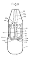
- Fig. 8 is a view illustrating the administering device that is completed, and to which a pump and a cap are attached
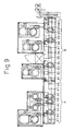
- Fig. 9 is a view illustrating an apparatus for production.
- Fig. 1 illustrates a step of inserting two filters in the container body.
- the container body 10 is made of a suitable resin in nearly a cylindrical shape with its one end open and having a closed bottom portion at the other end.
- the container 10 contains a powdered medicine in a predetermined amount enough for a plurality of times of administration.
- two filters 12 and 13 are inserted in the bottom portion.
- the container 10 is turned upside down so that the filters can be easily and reliably inserted; i.e., the container 10 is placed with its bottom portion facing upward.
- Two holes 10a and 10b are formed in the bottom wall of the container 10. These holes 10a and 10b are formed at positions of an equal distance from the center line of the container in the radial direction, and are maintaining a predetermined angle relative to the center line. This angle corresponds to a rotational angle ⁇ ( Fig. 6 ) along which the inner cylinder 15 turns between the filling position and the administering position that will be described later. Ring-like filter-fitting portions 11a and 11b are provided on the container on the outer sides of the holes 10a and 10b so that the filters 12 and 13 can be fitted thereto.
- One hole 10a has a size corresponding to a single-dose amount of the powdered medicine, and specifies the medicine-containing hole. Here, the capacity of the medicine-containing hole 10a can be finely adjusted depending upon the shape of the filter 12.
- a protrusion 14 is formed on the inside of the bottom of the container 10 along the center line. In the step of inserting the filters 12 and 13, the position of the container 10 in the rotational direction is determined by utilizing the protrusion 14.
- the filter 12 corresponding to the medicine-containing hole 10a is a dense filter, and has a protruded or recessed portion for finely adjusting the capacity of the hole 10a.
- the dense filter 12 as illustrated, possesses a protrusion.
- the dense filter 12 may have a recess. Therefore, the filter must be inserted in the fitting portion 11a while defining the up-and-down insertion direction such that the protrusion or the recess faces the side of the measuring hole 10a.
- the filter 13 fitted to the other hole 10b which is the air hole is a coarse filter. The volume of the hole 10b need not be adjusted. Therefore, the limitation of up-and-down direction is not imposed on the filter 13 that is inserted in the fitting portion 11b.
- the coarse filter 13 is inserted, first, in the fitting portion 11b. Then, the dense filter 12 is inserted in the fitting portion 11a.
- the up-and-down direction of the dense filter 12 is checked by using a sensor such as a micro-gauge. When the up-and-down direction of the dense filter 12 is reversed, this filter is not used, or this filter is used upon turning the same in the up-and-down direction (inverting the concave/convex direction).
- the filters 12 and 13 to be inserted are of a column shape. However, as there is almost no clearance relative to the fitting portions 11a and 11b, a guide (not shown) is used at the time of insertion. Further, the depth of insertion of the filter is checked by using a cylinder sensor and a photo sensor.
- the step of inserting the filters of Fig. 1 is conducted on a conveyer A.
- the conveyer A moves the workpiece linearly and intermittently, so that the processings are executed at stations A1 to A8.
- a stage A1 is idle and, at a stage A2, the container 10 is transferred onto the conveyer A by utilizing the XY-axis cylinder. The position of the container 10 that is transferred is detected by a cylinder sensor and a photo sensor.
- a stage A3 is idle, and the coarse filter 13 is inserted at a stage A4.
- the dense filter 12 is provisionally inserted and, at a stage A6, the dense filter 12 is tightly press-inserted and the depth of insertion is detected by a cylinder sensor and a photo sensor.
- the depth of insertion of the dense filter 12 is confirmed by a digital gauge, and the presence of the coarse filter 13 is also detected.
- the workpiece of container is transferred onto a second conveyer B.
- the workpiece (container 10) is turned upside down.
- the second conveyer B moves the workpiece linearly and intermittently, so that the processings are executed at stations B1 to B12.
- the work (container) is transferred onto the second conveyer B and, at a stage B2, air is injected and simultaneously sucked to clean the interior of the container 10.
- Fig. 2 illustrates a step (stage B3) of inserting the inner cylinder in the body.
- the inner cylinder 15 for introducing the powdered medicine is integrally constituted, of resin, of a bottom portion 15a having a diameter nearly same as or slightly smaller than the inner bottom wall surface of the container 10, and a cylindrical portion 15b having a medicine introduction passage 18 extending therein in the up-and-down direction.
- the cylindrical portion 15b has, at its upper portion, a sectional portion 15c of a noncircular shape (e.g., a home base-like pentagonal shape of which the two neighboring angles become 90 degrees) for transmitting the rotation, and a rotary shaft portion 15d.
- a noncircular shape e.g., a home base-like pentagonal shape of which the two neighboring angles become 90 degrees
- a hole 16 that rotatably fits to the central protrusion 14 of the container 10.
- a through opening 17 is formed on one side and, on the other side, a medicine introduction passage 18 is opened at the bottom surface.
- the opening 17 is penetrating through the bottom portion 15a, in the up-and-down direction, and it assumes a shape that is widened upward as shown in Fig. 6 to enable the medicine-containing hole 10a to be easily filled with the powdered medicine contained in the container 10.
- the medicine introduction passage 18 has its lower end opened in the lower surface of the bottom portion 15a, and extends upward and in an inclined manner from this opening portion up to the center axis of the cylindrical portion 15b and, further, extends upward along the center axis and is opened at the upper end of the noncircular portion 15c.
- the position of the inner cylinder 15 in the rotational direction is determined by utilizing the noncircular portion 15c at the upper end thereof.
- the depth of insertion of the inner cylinder 15 in the container body 10 is checked by the cylinder sensor and the photo sensor.
- the interior of the container body 10 is cleaned with the air at a stage B4 while being held by the inner cylinder 15.
- a stage B5 is idle, and the powdered medicine is filled at a stage B6.
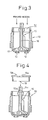
- Fig. 3 illustrates a step (stage B6) for filling the container body with the powdered medicine of a predetermined amount for a plurality of times of administration.
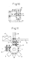
- the powdered medicine must be filled through a ring-like opening 52 between the container 10 and the inner cylinder 15 and, hence, a filling funnel 50 is used as shown in Fig. 10 .
- the filling funnel 50 has a ring-like medicine outlet 51 corresponding to the ring-like opening 52 of the workpiece (container body) 10.
- the container 10 is vibrated.
- the filling funnel 50 has a double structure to prevent the positional deviation of the inner cylinder 15 due to vibration, to prevent dispersion, and to prevent the adhesion of the powdered medicine on the inner cylinder 15 at the time of filling.
- a shutter is used to close the ring-like medicine outlet 51 thereby to collect the dust from local area.
- the solid line represents a state where the filling funnel 50 is retreated upward and a broken line represents a filling state where the filling funnel 50 is lowered down to a position where it comes in contact with the container 10.
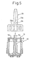
- Fig. 4 illustrates a step for inserting the inner closure in the container body.
- the inner closure 19 is integrally molded by using a resin, and includes a nearly circular closure portion for the container 10 and a cylindrical portion that fits to the upper inner wall surface of the container 10. At a central position of the closure portion, there is formed a hole 19a to which will be rotatably fitted a portion of the rotary shaft 15d of the inner cylinder 15. Further, a protrusion 19b is provided at a position spaced away from the center hole 19a in the radial direction to protrude outward beyond the closure portion so as to be fitted to a arch-shaped slit 20b ( Fig. 5 ) for limiting the angle of rotation of the nozzle 20 that will be described later.
- the inner closure 19 is inserted in two stages. Namely, in the production apparatus of Fig. 9 , a stage B7 is idle, and a stage B8 is for provisionally inserting the inner closure 19 (first stage). In the first stage, the inner closure 19 is provisionally inserted by utilizing the XY-axis cylinder. The inner closure 19 is positioned in the rotational direction by chucking the protrusion 19b of the inner closure 19 that is air-adsorbed. To prevent the positional deviation and movement of the inner cylinder 15 when the inner closure 19 is inserted, the inner cylinder 15 is inserted in a fixed manner while holding the upper end of the noncircular portion 15c of the inner cylinder 15. The depth of insertion is checked by using the cylinder sensor and the photo sensor. The holder portion of the inner cylinder 15, i.e., the pentagonal portion at the upper end is of a tapered structure, and the inner cylinder 15 is corrected for its position simultaneously when it is being inserted.
- stage B9 of inserting the inner closure 19 the inner closure 19 is press-inserted in the container 10 by utilizing a short-axis cylinder.
- the inner cylinder 15 is inserted while being held to prevent the positional deviation and shakiness of the inner cylinder 15.
- the depth of insertion is checked by the cylinder sensor and the photo sensor.
- the position of the inner cylinder 15 is also corrected at the same time by utilizing the holder portion of the inner cylinder 15.
- Fig. 5 is a view illustrating a step for inserting the nozzle.
- a stage B10 is idle and a stage B11 is for inserting the nozzle.
- the nozzle 20 is integrally constituted of a resin and includes a portion forming a passage 20a for the powdered medicine and a cylindrical portion which rotatably fits to the upper peripheral surface of the container 10, and has a arch-shaped slit 20b that fits to the protrusion 19b of the inner closure 19. Further, the nozzle 20 has a noncircular hole 20c that fits to the noncircular portion 15c at the upper end of the inner cylinder 15. This transmits the rotation of the nozzle 20 to the inner cylinder 15.
- the nozzle 20 is inserted by utilizing the XY-axis cylinder.
- the nozzle 20 is positioned in the rotational direction by inserting a noncircular pin (not shown) in the noncircular hole 20c of the nozzle 20 that is air-adsorbed.
- the depth of insertion of the nozzle 20 in the container 10 is checked by the cylinder sensor and the photo sensor.
- an assembled product of the powdered medicine multi-dose administering device is completed as shown in Fig. 7 , and is transferred to an inspection machine at the next step from the second conveyer B in the stage B12 of Fig. 9 .
- the product is discharged prior to being transferred to the inspection machine.
- Fig. 11 is a view illustrating a step of inspecting the assembly filled with the medicine.
- the assemblies are, first, placed in pairs on an electronic balance 30 by utilizing the XY-axis cylinder.
- the electronic balance 30 is provided with a windbreak.
- the assembled products are placed in pairs on a rotary index table 32 (first stage) by utilizing the XY-axis cylinder.
- first stage a rotary index table 32
- pairs of assembled products are successively sent to the first to seventh stages (I to VII) where they are inspection processed.
- the assembled products are positioned in the rotational direction by utilizing the protrusion of the filter-fitting portion.
- the nozzle 20 is turned counterclockwise by a predetermined angle by utilizing the rotary cylinder.
- the rotational torque is measured by using a load cell.
- the chuck portions that come in contact with the nozzle are made of a tubular urethane rubber of a circular shape that are arranged maintaining a predetermined distance to prevent the local contact with the product and to suppress the wear of the rubber.
- the nozzle 20 and the inner cylinder 15 are at the filling position where the opening 17 of the inner cylinder 15 is communicated with the medicine-containing hole 10a, and the medicine-containing hole 10 is filled with the powdered medicine in the container 10 due to its own weight.
- the product is vibrated up and down (by tapping) by a roller cam driven by a servo motor.
- This enables the medicine-containing hole 10a to be reliably filled with the powdered medicine of a predetermined amount.
- shock absorbers are placed on and under the vibrating portion.
- the nozzle 20 is turned clockwise by utilizing the rotary cylinder.
- the rotational torque is measured by using the load cell.
- the chuck portions that come in contact with the nozzle are made of a tubular urethane rubber of a circular shape that are arranged maintaining a predetermined distance to prevent the local contact with the product and to suppress the wear of rubber. Due to the rotation, the nozzle 20 and the inner cylinder 15 of the assembly are at the administering positions, and the medicine-containing hole 10a is in a state of being communicated with the medicine passages 18 and 20a.
- the air is sucked from the end of the nozzle 20 and, at the same time, the compressed air is injected, as a pulse, through the filter 12 to spray the powdered medicine.
- This state of spraying is inspected as being the practically established state using the pump 21 ( Fig. 8 ) of the powdered medicine multi-dose administering device.
- a sixth stage is idle and, at the seventh and last stage, the assembled products are placed on the electronic balance 34 by utilizing the XY-axis cylinder, and the weight is measured after the spraying.
- the electronic balance 34 is installed on a vibration-proof plate and is provided with a windbreak.
- the assembled products are placed on the index table by utilizing the XY-axis cylinder.
- the amount sprayed is calculated from the difference of weights before and after the spraying.
- the measured results are displayed on the control board/display unit 40.
- the acceptable products of which the one time of spraying amount is within a predetermined range e.g., 15 mg ⁇ 1.5 mg
- the acceptable products of which the one time of spraying amount is within a predetermined range are discharged to a takeout port through an acceptable product discharge chute 36 and the assembled products that are determined to be defective are discharged through a defective product discharge chute 38.
- a powdered medicine multi-dose (many times) administering device is completed as shown in Fig. 8 .
- the cap 22 is removed.
- the device is in the state of after an administration and the inner cylinder 15 is at the administering position. Therefore, the medicine-containing hole 10a in the bottom surface of the container 10 is opened to the medicine passage 18 in the inner cylinder 15 and is communicated with the exterior.
- the nozzle 20 is turned counterclockwise by a predetermined angle.
- This rotational angle is limited because the protrusion 19b of the inner closure 19 has been engaged with the arch-shaped slit 20b of the nozzle 20.
- the inner cylinder 15 coupled to the nozzle 20 so as to transmit the rotation and is turned counterclockwise by the same angle ⁇ as that of the nozzle 20 as shown in Fig. 6 .
- Blades 15f work to stir the powdered medicine in the container as the inner cylinder 15 is turned, and the amount of medicine does not deviate.
- the opening 17 in the inner cylinder 15 is positioned on the medicine-containing hole 11a which, therefore, is filled with the powdered medicine in the container 10, due to its own weight, through the opening 17.
- the single-dose amount of the powdered medicine is adjusted by the protrusion or recess of the filter 12 as described earlier.
- the interior of the pump 21 is communicated with the exterior through the filter 13, hole 10b and passages 18, 20a. At the time of filling the medicine-containing hole 10a with the powdered medicine through the opening 17, therefore, the air escapes therethrough, and the medicine is smoothly filled.
- the nozzle 20 is returned clockwise by the predetermined angle ⁇ .
- the inner cylinder 15, too, is turned clockwise by the same angle ⁇ .
- the medicine-containing hole 10a is once swept by the bottom surface of the inner cylinder 15 to measure the single-dose amount of the powdered medicine.
- the administering position is reached where the medicine passage 18 of the inner cylinder 15 is brought to a position where it is communicated with the medicine-containing hole 10a.
- the pump 21 is depressed to blow the air into the powdered medicine-containing hole 10a through the filter 12, whereby the powdered medicine is injected to the exterior through the medicine passage 18 in the inner cylinder and through the medicine injection passage 20a of the nozzle 20, and the powdered medicine is applied to a diseased part.
- the hole 10b is closed by the lower surface of the inner cylinder 15. Therefore, the pressure produced by the pump 21 is effectively used for blowing out the medicine.
- an apparatus and a method of automatically assembling the parts of the powdered medicine multi-dose administering device automatically filling the powdered medicine and of automatically conducting the inspection after the assembly. That is, through the steps of production and assembly, the workpieces are transferred onto a known straight-forward conveyer and a rotary index table, and the individual parts are assembled on a completely automated line that includes an XY-axis cylinder and a rotary cylinder.
- the production efficiency is greatly enhanced. Further, mistakes are prevented owing to correct inspection, and the occurrence of defective products is minimized.
Landscapes
- Health & Medical Sciences (AREA)
- Life Sciences & Earth Sciences (AREA)
- Engineering & Computer Science (AREA)
- Veterinary Medicine (AREA)
- Public Health (AREA)
- General Health & Medical Sciences (AREA)
- Animal Behavior & Ethology (AREA)
- Heart & Thoracic Surgery (AREA)
- Biomedical Technology (AREA)
- Hematology (AREA)
- Anesthesiology (AREA)
- Pulmonology (AREA)
- Bioinformatics & Cheminformatics (AREA)
- Biophysics (AREA)
- Physics & Mathematics (AREA)
- General Physics & Mathematics (AREA)
- Basic Packing Technique (AREA)
- Medical Preparation Storing Or Oral Administration Devices (AREA)
Claims (31)
- Verfahren zur Herstellung einer Mehrfachdosisverabreichungsvorrichtung für ein pulverförmiges Arzneimittel, umfassend:einen Behälter (10), welcher dazu in der Lage ist, eine Mehrfachdosismenge pulverförmigen Arzneimittels zu speichern, und welcher aufweist:ein Loch (10a) zum Aufnehmen einer Einzeldosismenge des Arzneimittels und einen Filterpassbereich (11a), welche in dem Bodenbereich des Behälters bereitgestellt sind,ein erstes Filter (12), welches in den ersten Filterpassbereich eingepasst ist,ein zweites Loch (10b) und einen zweiten Filterpassbereich (11b), welche in dem Bodenbereich des Behälters bereitgestellt sind,ein zweites Filter (13), welches gröber ist als das erste Filter (12) und an den zweiten Filterpassbereich (11b) angepasst ist,einen Innenzylinder (15), welcher zwischen einer Füllposition und einer Verabreichungsposition rotierbar ist, während Kontakt mit der inneren Bodenoberfläche des Behälters aufrechterhalten wird,wobei ein Innenverschluss (19) mit einem Zentrumsloch zum rotierbaren Halten eines oberen Teils des Innenzylinders und zum Verschließen einer Öffnung an dem oberen Ende des Behälters an die innere Peripherie der Öffnung an dem oberen Teil des Behälters angepasst ist, undeine Düse (20), welche an das obere Ende des Innenzylinders gekoppelt ist, um die Rotation zu übertragen, und an die äußere Peripherie der Öffnung an dem oberen Teil des Behälters rotierbar angepasst ist und einen Arzneimittelabgabedurchlass (20a) aufweist,wobei in der Füllposition das pulverförmige Arzneimittel in dem Behälter dem Arzneimittelaufnahmeloch (10a) durch eine Öffnung (17) in dem Innenzylinder hindurch zugeführt wird und das zweite Filter und das zweite Loch mit einem Arzneimitteldurchlass (18) in dem Innenzylinder in Verbindung stehen, und wobei in der Verabreichungsposition Luft durch das erste Filter hindurch in das Arzneimittelaufnahmeloch (10a) geblasen wird, so dass das Arzneimittel in dem Arzneimittelaufnahmeloch durch den Arzneimitteldurchlass (18) des Innenzylinders und durch den Arzneimittelabgabedurchlass (20a) der Düse hindurch nach außen abgegeben wird;wobei das Verfahren zur Herstellung einer Mehrfachdosisverabreichungsvorrichtung für ein pulverförmiges Arzneimittel die Schritte umfasst:Einfügen des zweiten Filters (13) in den zweiten Filterpassbereich (11b);Einfügen des ersten Filters (12) in den ersten Filterpassbereich (11a);Einfügen des Innenzylinders (15) in den Behälterkörper (10);Befüllen des Behälters mit dem pulverförmigen Arzneimittel;Einfügen des Innenverschlusses (19) in den Behälter und Anpassen desselben an den Innenzylinder; undAnpassen der Düse (20) an den Behälter, um sie an den Innenzylinder zu koppeln.
- Verfahren zur Herstellung einer Mehrfachdosisverabreichungsvorrichtung für ein pulverförmiges Arzneimittel nach Anspruch 1, wobei in dem Schritt des Einfügens des ersten und des zweiten Filters (12, 13) der Behälter (10) so installiert wird, dass sein Bodenbereich nach oben gewandt ist.
- Verfahren zur Herstellung einer Mehrfachdosisverabreichungsvorrichtung für ein pulverförmiges Arzneimittel nach Anspruch 1, wobei in dem Schritt des Einfügens des ersten und des zweiten Filters (12, 13) das Einfügen durchgeführt wird, während Einfügeführungen auf den ersten bzw. zweiten Filterpassbereich (11a, 11b) angewendet werden.
- Verfahren zur Herstellung einer Mehrfachdosisverabreichungsvorrichtung für ein pulverförmiges Arzneimittel nach Anspruch 1, wobei zur Zeit des Einfügens des ersten Filters (12) in den ersten Filterpassbereich (11a) die Auf-und-Ab-Richtung des Filters bestätigt wird, während zur Zeit des Einfügens des zweiten Filters (13) in den zweiten Filterpassbereich (11b) die Auf-und-Ab-Richtung des Filters nicht bestätigt wird.
- Verfahren zur Herstellung einer Mehrfachdosisverabreichungsvorrichtung für ein pulverförmiges Arzneimittel nach Anspruch 1, wobei beim Einfügen des ersten Filters (12) in den ersten Filterpassbereich (11a) das erste Filter in einem ersten Schritt provisorisch eingefügt wird und dann in einem nächsten Schritt eingepresst wird.
- Verfahren zur Herstellung einer Mehrfachdosisverabreichungsvorrichtung für ein pulverförmiges Arzneimittel nach Anspruch 1, wobei das zweite Filter (13) in den zweiten Filterpassbereich (11b) eingefügt wird, dann die Einfügetiefe des zweiten Filters gemessen wird und das erste Filter (12) in den ersten Filterpassbereich (11a) eingepresst wird, dann die Einpresstiefe des ersten Filters (12) gemessen wird.
- Verfahren zur Herstellung einer Mehrfachdosisverabreichungsvorrichtung für ein pulverförmiges Arzneimittel nach Anspruch 1, wobei nach dem Einfügen des ersten und des zweiten Filters (12, 13) in den ersten und zweiten Filterpassbereich (11a, 11b) der Behälter (10) umgedreht wird.
- Verfahren zur Herstellung einer Mehrfachdosisverabreichungsvorrichtung für ein pulverförmiges Arzneimittel nach Anspruch 7, wobei die Schritte des Einfügens des ersten und des zweiten Filters (12, 13) ausgeführt werden, während der Behälter (10) mittels eines ersten Förderers gefördert wird, und wobei die Schritte nach dem Umdrehen des Behälters (10) ausgeführt werden, während der Behälter (10) mittels eines zweiten Förderers gefördert wird.
- Verfahren zur Herstellung einer Mehrfachdosisverabreichungsvorrichtung für ein pulverförmiges Arzneimittel nach Anspruch 8, wobei bei der Übergabe des Behälters (10) auf den ersten Förderer die Position des Behälters (10) in der Rotationsrichtung bestimmt wird durch Verwendung eines Vorsprungs (14), welcher an einer zentralen Position an der inneren Bodenoberfläche des Behälters bereitgestellt ist.
- Verfahren zur Herstellung einer Mehrfachdosisverabreichungsvorrichtung für ein pulverförmiges Arzneimittel nach Anspruch 8, wobei bei der Übergabe des Behälters (10) auf den zweiten Förderer die Position des Behälters (10) in der Rotationsrichtung bestimmt wird durch Verwendung des ersten und des zweiten Filterpassbereichs (11a, 11b), die von dem Bodenbereich des Behälters (10) nach außen ragen.
- Verfahren zur Herstellung einer Mehrfachdosisverabreichungsvorrichtung für ein pulverförmiges Arzneimittel nach Anspruch 8, wobei nach der Übergabe des Behälters (10) auf den zweiten Förderer das Innere des Behälters gereinigt wird durch Injizieren der komprimierten Luft in den Behälter und Absaugen der Luft vor dem Einfügen des Innenzylinders (15) in den Behälter.
- Verfahren zur Herstellung einer Mehrfachdosisverabreichungsvorrichtung für ein pulverförmiges Arzneimittel nach Anspruch 1, wobei beim Einfügen des Innenzylinders (15) in den Behälter die Position des Innenzylinders in der Rotationsrichtung bestimmt wird durch Verwendung eines nicht-kreisförmigen Bereichs, welcher an einem Bereich gebildet ist, der an die Düse an dem oberen Ende des Innenzylinders (15) gekoppelt ist.
- Verfahren zur Herstellung einer Mehrfachdosisverabreichungsvorrichtung für ein pulverförmiges Arzneimittel nach Anspruch 1, wobei nach dem Einfügen des Innenzylinders (15) in den Behälter die Einfügetiefe des Innenzylinders gemessen wird.
- Verfahren zur Herstellung einer Mehrfachdosisverabreichungsvorrichtung für ein pulverförmiges Arzneimittel nach Anspruch 1, wobei nach dem Einfügen des Innenzylinders (15) in den Behälter der Behälter gereinigt wird durch Zuführen von Luft in denselben hinein, während das Innere des Behälters mittels des Innenzylinders gehalten wird.
- Verfahren zur Herstellung einer Mehrfachdosisverabreichungsvorrichtung für ein pulverförmiges Arzneimittel nach Anspruch 1, wobei in dem Schritt des Befüllens des Behälters mit dem pulverförmigen Arzneimittel der Behälter mit dem pulverförmigen Arzneimittel über eine ringartige Öffnung zwischen der Öffnung an dem oberen Ende des Behälters und dem Innenzylinder (15) durch die Verwendung eines Fülltrichters befüllt wird.
- Verfahren zur Herstellung einer Mehrfachdosisverabreichungsvorrichtung für ein pulverförmiges Arzneimittel nach Anspruch 1, wobei in dem Schritt des Befüllens des Behälters mit dem pulverförmigen Arzneimittel der Behälter vibriert wird.
- Verfahren zur Herstellung einer Mehrfachdosisverabreichungsvorrichtung für ein pulverförmiges Arzneimittel nach Anspruch 1, wobei in dem Schritt des Einfügens des Innenverschlusses (19) in den Behälter der Innenverschluss an die innere Peripherie der Öffnung an dem oberen Teil des Behälters fest angepasst wird und gleichzeitig der Rotationswellenbereich (15d) an dem oberen Teil des Innenzylinders an das Zentrumsloch des Innenverschlusses auf nicht-feste Weise angepasst wird.
- Verfahren zur Herstellung einer Mehrfachdosisverabreichungsvorrichtung für ein pulverförmiges Arzneimittel nach Anspruch 17, wobei in dem Schritt des Einfügens des Innenverschlusses (19) in den Behälter der Innenverschluss in einem ersten Schritt provisorisch in den Behälter eingefügt wird und dann in einem nächsten Schritt in den Behälter eingepresst wird.
- Verfahren zur Herstellung einer Mehrfachdosisverabreichungsvorrichtung für ein pulverförmiges Arzneimittel nach Anspruch 18, wobei beim Einpressen des Innenverschlusses (19) in den Behälter der Innenverschluss in den Behälter eingepresst wird, während das obere Ende des Innenzylinders (15), welches über den Innenverschluss hinaus nach oben ragt, gehalten wird.
- Verfahren zur Herstellung einer Mehrfachdosisverabreichungsvorrichtung für ein pulverförmiges Arzneimittel nach Anspruch 19, wobei beim Halten des oberen Endes des Innenzylinders (15) gleichzeitig die Position des Innenzylinders korrigiert wird durch Verwendung des nicht-kreisförmigen Wellenbereichs (15c) an dem oberen Ende des Innenzylinders.
- Verfahren zur Herstellung einer Mehrfachdosisverabreichungsvorrichtung für ein pulverförmiges Arzneimittel nach Anspruch 1, wobei nach dem Einpassen des Innenverschlusses (19) in den Behälter und Anpassen desselben an den Innenzylinder die Einfügetiefe des Innenverschlusses gemessen wird.
- Verfahren zur Herstellung einer Mehrfachdosisverabreichungsvorrichtung für ein pulverförmiges Arzneimittel nach Anspruch 20, wobei in dem Schritt des Einfügens der Düse (20) in den Behälter die Düse auf nicht-feste Weise an die äußere Peripherie der Öffnung an dem oberen Teil des Behälterkörpers angepasst wird und gleichzeitig ein nichtkreisförmiges Loch (20c) der Düse an den nicht-kreisförmigen Wellenbereich (15c) an dem oberen Ende des Innenzylinders auf rotations-übertragende Weise angepasst wird.
- Verfahren zur Herstellung einer Mehrfachdosisverabreichungsvorrichtung für ein pulverförmiges Arzneimittel nach Anspruch 22, wobei in dem Schritt des Einfügens der Düse (20) in den Behälter ein Stift in das zu dem nicht-kreisförmigen Bereich an dem oberen Ende des Innenzylinders (15) korrespondierende nicht-kreisförmige Loch (20c) der Düse vor dem Einfügen der Düse eingefügt wird, um dadurch die Position der Düse in der Rotationsrichtung zu bestimmen.
- Verfahren zur Herstellung einer Mehrfachdosisverabreichungsvorrichtung für ein pulverförmiges Arzneimittel nach Anspruch 1, wobei nach dem Einfügen der Düse (20) in den Behälter die Einfügetiefe der Düse gemessen wird.
- Verfahren nach Anspruch 1, wobei die Mehrfachdosisverabreichungsvorrichtung für ein pulverförmiges Arzneimittel zusammengebaut wird durch:Inkorporieren eines ersten und eines zweiten Filters (12, 13) an der Außenseite eines Bodenbereichs eines Behälters (10) mit nach oben positioniertem Bodenbereich, wobei das zweite Filter (13) gröber ist als das erste Filter (12);Umdrehen des Behälters, so dass das offene Ende des Behälters nach oben gewandt ist;Einfügen des Innenzylinders (15) in den Behälter über die offenendige Seite des Behälters;Befüllen des Behälters mit einer vorbestimmten Menge an pulverförmigem Arzneimittel über die offenendige Seite des Behälters;Sichern und Anpassen des Innenverschlusses (19) an das offene Ende des Behälters sowie an den Innenzylinder, so dass der Innenzylinder von dem Behälter teilweise nach außen ragt; undrotierbares Anpassen der Düse (20) an das offene Ende des Behälters, während sie an den Innenverschluss (19) in einer die Rotation übertragenden Weise gekoppelt wird.
- Verfahren zur Herstellung einer Mehrfachdosisverabreichungsvorrichtung für ein pulverförmiges Arzneimittel nach Anspruch 1, ferner umfassend den Schritt:Prüfen der so erhaltenen Anordnung nach Anpassen der Düse an den Behälter.
- Verfahren zur Herstellung einer Mehrfachdosisverabreichungsvorrichtung für ein pulverförmiges Arzneimittel nach Anspruch 26, wobei in einem Zustand, in dem die Anordnung erhalten ist, der Innenzylinder (15) in die Verabreichungsposition gesetzt ist und der Schritt des Prüfens der Anordnung die folgenden Unterschritte umfasst:einen ersten Mess-Unterschritt des Messens der Anfangsladung der Anordnung;Drehen der Düse (20) um einen vorbestimmten Winkel relativ zu dem Behälterkörper, um den Innenzylinder in die Füllposition zu bringen;Vibrieren der Anordnung;Drehen der Düse in der entgegengesetzten Richtung um einen vorbestimmten Winkel relativ zu dem Behälterkörper, um den Innenzylinder in die Verabreichungsposition zu bringen;Absaugen der Luft vom Ende der Düse (20), während die komprimierte Luft durch das Filter hindurch injiziert wird, so dass eine Einzeldosismenge des pulverförmigen Arzneimittels in dem Arzneimittelaufnahmeloch (10a) aus der Düse injiziert wird; undeinen zweiten Mess-Unterschritt des Messens der Ladung der Anordnung nach der Injektion und Berechnen der Injektionsmenge aus der Gewichtsdifferenz zwischen der Zeit vor und nach der Injektion; und wobeider erste und der zweite Mess-Unterschritt mittels einer elektronischen Waage, welche mit einem Windschutz versehen ist, durchgeführt werden.
- Verfahren zur Herstellung einer Mehrfachdosisverabreichungsvorrichtung für ein pulverförmiges Arzneimittel nach Anspruch 27, wobei nach dem Messen der Anfangsladung der Anordnung die Anordnung auf den Indextisch übergeben wird und die einzelnen Unterschritte in dem Schritt des Prüfens durchgeführt werden, während der Indextisch gedreht wird.
- Verfahren zur Herstellung einer Mehrfachdosisverabreichungsvorrichtung für ein pulverförmiges Arzneimittel nach Anspruch 27, wobei in den vorstehenden zwei Unterschritten des Drehens der Düse relativ zu dem Behälterkörper ein Rotationszylinder verwendet wird und ein Urethankautschuk an dem Spannbereich des Rotationsylinders, der mit der Düse in Kontakt kommt, angeordnet ist.
- Anordnung einer Mehrfachdosisverabreichungsvorrichtung für ein pulverförmiges Arzneimittel, umfassend:einen Behälterkörper (10), welcher dazu in der Lage ist, eine Mehrfachdosismenge eines pulverförmigen Arzneimittels zu speichern, und welcher in seinem Bodenbereich ein erstes Loch (10a) zum Aufnehmen einer Einzeldosismenge des Arzneimittels und einen Filterpassbereich (11a) aufweist;ein erstes Filter (12), welches in den ersten Filterpassbereich eingepasst ist, einen Innenzylinder (15), welcher zwischen einer Füllposition und einer Verabreichungsposition rotierbar ist, während Kontakt mit der inneren Bodenoberfläche des Behälters aufrechterhalten wird;wobei ein Innenverschluss (19) mit einem Zentrumsloch zum rotierbaren Halten eines oberen Teils des Innenzylinders und zum Verschließen einer Öffnung an dem oberen Ende des Behälters an die innere Peripherie der Öffnung an dem oberen Teil des Behälters angepasst ist,eine Düse (20), welche an das obere Ende des Innenzylinders gekoppelt ist, um die Rotation zu übertragen, und welche an die äußere Peripherie der Öffnung an dem oberen Teil des Behälters rotierbar angepasst ist und einen Arzneimittelabgabedurchlass (20a) aufweist;wobei in der Füllposition das pulverförmige Arzneimittel in dem Behälter dem Arzneimittelaufnahmeloch (10a) durch eine Öffnung (17) in dem Innenzylinder hindurch zugeführt wird und in der Verabreichungsposition die Luft durch das erste Filter hindurch in das Arzneimittelaufnahmeloch (10a) geblasen wird, so dass das Arzneimittel in dem Arzneimittelaufnahmeloch durch einen Arzneimitteldurchlass (18) des Innenzylinders und durch den Arzneimittelabgabedurchlass (20a) der Düse hindurch nach außen abgegeben wird; undwobei ein zweites Loch (10b) und ein zweiter Filterpassbereich (11b) in dem Bodenbereich des Behälters bereitgestellt sind, wobei ein zweites Filter (13), welches gröber ist als das erste Filter (12), an den zweiten Filterpassbereich (11b) angepasst ist, und wobei das zweite Filter und das zweite Loch mit dem Arzneimitteldurchlass (18) in dem Innenzylinder bei der Füllposition in Verbindung stehen.
- Mehrfachdosisverabreichungsvorrichtung für ein pulverförmiges Arzneimittel, welche umfasst:eine Anordnung nach Anspruch 30 undeine Pumpe (21), welche dazu in der Lage ist, Luft durch das erste Filter (12) hindurch in das erste Loch (10a) zu blasen;wobei in der Füllposition das pulverförmige Arzneimittel in dem Behälter dem Arzneimittelaufnahmeloch (10a) durch eine Öffnung (17) in dem Innenzylinder hindurch zugeführt wird und in der Verabreichungsposition die Luft durch das erste Filter hindurch in das Arzneimittelaufnahmeloch (10a) geblasen wird, so dass das Arzneimittel in dem Arzneimittelaufnahmeloch durch einen Arzneimitteldurchlass (18) des Innenzylinders und durch den Arzneimittelabgabedurchlass (20a) der Düse hindurch nach außen abgegeben wird; undwobei ein zweites Loch (10b) und ein zweiter Filterpassbereich (11b) in dem Bodenbereich des Behälters bereitgestellt sind, wobei ein zweites Filter (13), welches gröber ist als das erste Filter (12), an den zweiten Filterpassbereich (11b) angepasst ist, und wobei das zweite Filter und das zweite Loch mit dem Arzneimitteldurchlass (18) in dem Innenzylinder bei der Füllposition in Verbindung stehen.
Applications Claiming Priority (3)
| Application Number | Priority Date | Filing Date | Title |
|---|---|---|---|
| JP2002207371 | 2002-07-16 | ||
| JP2002207371 | 2002-07-16 | ||
| PCT/JP2003/009036 WO2004007007A1 (ja) | 2002-07-16 | 2003-07-16 | 粉末薬剤多回投与器の製造方法および装置 |
Publications (3)
| Publication Number | Publication Date |
|---|---|
| EP1522324A1 EP1522324A1 (de) | 2005-04-13 |
| EP1522324A4 EP1522324A4 (de) | 2006-12-20 |
| EP1522324B1 true EP1522324B1 (de) | 2012-10-10 |
Family
ID=30112818
Family Applications (1)
| Application Number | Title | Priority Date | Filing Date |
|---|---|---|---|
| EP03764214A Expired - Lifetime EP1522324B1 (de) | 2002-07-16 | 2003-07-16 | Verfahren und vorrichtung zur herstellung eines multiplen dosierspenders für ein pulverförmiges medikament |
Country Status (13)
| Country | Link |
|---|---|
| US (1) | US7611078B2 (de) |
| EP (1) | EP1522324B1 (de) |
| JP (2) | JP4064965B2 (de) |
| KR (1) | KR100984647B1 (de) |
| CN (1) | CN1330390C (de) |
| AU (1) | AU2003248075B2 (de) |
| BR (1) | BRPI0305513B1 (de) |
| CA (1) | CA2460466C (de) |
| ES (1) | ES2393473T3 (de) |
| MX (1) | MXPA04002092A (de) |
| NZ (1) | NZ531756A (de) |
| WO (1) | WO2004007007A1 (de) |
| ZA (1) | ZA200401837B (de) |
Families Citing this family (7)
| Publication number | Priority date | Publication date | Assignee | Title |
|---|---|---|---|---|
| DE102006053421A1 (de) * | 2006-11-13 | 2008-05-15 | Epcos Ag | Vibrationsgenerator |
| PE20100117A1 (es) | 2008-05-23 | 2010-03-03 | Otsuka Pharma Co Ltd | Inhalador de polvo |
| DK2425214T3 (da) * | 2009-04-29 | 2013-08-12 | Wilco Ag | Fremgangsmåde til test af doseringsapparater og indretning dertil. |
| US20170348496A1 (en) * | 2014-12-17 | 2017-12-07 | Norton (Waterford) Limited | Can and Actuator Assembly |
| DE102015119617A1 (de) * | 2015-11-13 | 2017-05-18 | Alfred Von Schuckmann | Handbetätigbarer Inhalator |
| JP7261382B2 (ja) * | 2018-08-06 | 2023-04-20 | 大日本印刷株式会社 | 液体計量装置および液体計量装置付き容器 |
| KR102271888B1 (ko) * | 2020-12-07 | 2021-07-01 | 주식회사 프리코 | 공유공간 관리 시스템 |
Family Cites Families (14)
| Publication number | Priority date | Publication date | Assignee | Title |
|---|---|---|---|---|
| US4224979A (en) * | 1977-10-31 | 1980-09-30 | Mcneil Corporation | Automatic foundry system |
| US4487696A (en) * | 1978-08-14 | 1984-12-11 | Ferrara Louis T | Blood separator and dispenser |
| US5238153A (en) * | 1991-02-19 | 1993-08-24 | Pilkington Visioncare Inc. | Dispenser for dispersing sterile solutions |
| US5423216A (en) * | 1992-12-24 | 1995-06-13 | Shin-Etsu Chemical Co., Ltd. | Apparatus for automatically determining bulk specific gravity of powdery product |
| WO1994026338A1 (fr) | 1993-05-12 | 1994-11-24 | Teijin Limited | Dispositif et procede de distribution de medicaments en poudre en doses multiples |
| US5605257A (en) * | 1996-03-04 | 1997-02-25 | Beard; Walter C. | Sterile liquid squeeze-bottle-type dispenser |
| US6325475B1 (en) * | 1996-09-06 | 2001-12-04 | Microfab Technologies Inc. | Devices for presenting airborne materials to the nose |
| JP3883653B2 (ja) * | 1997-07-16 | 2007-02-21 | 帝人株式会社 | 粉末薬剤マルチドーズ投与デバイス |
| DE60030362T2 (de) | 1999-01-14 | 2007-06-21 | Teijin Ltd. | Gerät zur verabreichung einer konstanten pulvermenge |
| JP3671789B2 (ja) * | 2000-01-13 | 2005-07-13 | 株式会社村田製作所 | 部品の取扱装置および取扱方法 |
| WO2001060695A1 (en) * | 2000-02-18 | 2001-08-23 | Glaxo Group Limited | System and method for check-weighing the content of a blister |
| US6415526B1 (en) * | 2000-04-28 | 2002-07-09 | Smithkline Beecham Corporation | Apparatus and method for measuring alignment of metered dose inhaler valves |
| US6824080B2 (en) * | 2000-06-12 | 2004-11-30 | Teijin Limited | Powdered medicine multi-dose administering device |
| EP1315533A4 (de) * | 2000-08-15 | 2007-06-27 | Univ Kentucky Res Found | Programmierbare mehrdosenvorrichtung für intranasale medikamentenverabreichung |
-
2003
- 2003-07-16 EP EP03764214A patent/EP1522324B1/de not_active Expired - Lifetime
- 2003-07-16 CA CA2460466A patent/CA2460466C/en not_active Expired - Fee Related
- 2003-07-16 MX MXPA04002092A patent/MXPA04002092A/es active IP Right Grant
- 2003-07-16 KR KR1020047003818A patent/KR100984647B1/ko not_active Expired - Fee Related
- 2003-07-16 AU AU2003248075A patent/AU2003248075B2/en not_active Ceased
- 2003-07-16 CN CNB038010682A patent/CN1330390C/zh not_active Expired - Fee Related
- 2003-07-16 BR BRPI0305513-2A patent/BRPI0305513B1/pt not_active IP Right Cessation
- 2003-07-16 JP JP2004521222A patent/JP4064965B2/ja not_active Expired - Fee Related
- 2003-07-16 NZ NZ531756A patent/NZ531756A/en not_active IP Right Cessation
- 2003-07-16 WO PCT/JP2003/009036 patent/WO2004007007A1/ja not_active Ceased
- 2003-07-16 ES ES03764214T patent/ES2393473T3/es not_active Expired - Lifetime
-
2004
- 2004-03-05 ZA ZA200401837A patent/ZA200401837B/en unknown
- 2004-03-16 US US10/489,662 patent/US7611078B2/en not_active Expired - Fee Related
-
2007
- 2007-08-13 JP JP2007211052A patent/JP4892706B2/ja not_active Expired - Fee Related
Also Published As
| Publication number | Publication date |
|---|---|
| MXPA04002092A (es) | 2005-02-17 |
| ES2393473T3 (es) | 2012-12-21 |
| CA2460466C (en) | 2010-07-06 |
| US7611078B2 (en) | 2009-11-03 |
| HK1070007A1 (en) | 2005-06-10 |
| EP1522324A4 (de) | 2006-12-20 |
| KR100984647B1 (ko) | 2010-10-01 |
| CA2460466A1 (en) | 2004-01-22 |
| AU2003248075B2 (en) | 2008-06-05 |
| JP4064965B2 (ja) | 2008-03-19 |
| BR0305513A (pt) | 2004-09-28 |
| JPWO2004007007A1 (ja) | 2005-11-10 |
| JP4892706B2 (ja) | 2012-03-07 |
| ZA200401837B (en) | 2004-09-07 |
| US20040237276A1 (en) | 2004-12-02 |
| EP1522324A1 (de) | 2005-04-13 |
| WO2004007007A1 (ja) | 2004-01-22 |
| JP2007289782A (ja) | 2007-11-08 |
| BRPI0305513B1 (pt) | 2015-07-28 |
| AU2003248075A1 (en) | 2004-02-02 |
| KR20050025294A (ko) | 2005-03-14 |
| CN1330390C (zh) | 2007-08-08 |
| CN1556718A (zh) | 2004-12-22 |
| NZ531756A (en) | 2007-11-30 |
Similar Documents
| Publication | Publication Date | Title |
|---|---|---|
| US20220225661A1 (en) | Systems and methods for automated production of cigarettes | |
| JP4892706B2 (ja) | 粉末薬剤多回投与器およびその組立体 | |
| KR101898877B1 (ko) | 분말형 충전물의 계량 장치 | |
| JPH0458340B2 (de) | ||
| CN218859269U (zh) | 定量出粉装置 | |
| HK1070007B (en) | Method and device of producing multiple doser for powdered medicine | |
| US20090162148A1 (en) | Feed Device for Conveying a Powdery Medium from a Powder Container into a Powder Conduit | |
| CN113000795B (zh) | 型芯成型装置 | |
| EP2947177A1 (de) | Beschichtungsvorrichtung für harzbehälter und herstellungssystem für harzbehälter | |
| JPH06345189A (ja) | 粉末秤量充填装置及びカプセル充填機 | |
| CN222330046U (zh) | 一种密封分装倒料自动化装置 | |
| CN113000796B (zh) | 型芯成型装置 | |
| JPS6111151Y2 (de) | ||
| CN210473884U (zh) | 一种用于弹性体的抗粘剂添加装置 | |
| KR20040042842A (ko) | 약제 피더 | |
| JP4258928B2 (ja) | 充填機の充填重量検査装置 | |
| CN120515310A (zh) | 一种具有防尘装置的高精度小料配方机 | |
| CN117902179A (zh) | 一种粉料存储斗 | |
| JPS5924449Y2 (ja) | 傾動可能な加工槽を有する遊星旋回式加工機 | |
| KR101207974B1 (ko) | 충전물 투입장치 제어방법 | |
| KR20000021561U (ko) | 액상물 포장기의 포장재 이송장치 | |
| JP2000254940A (ja) | 竪型射出成形機のパージング及び計量装置 | |
| JPWO1996006009A1 (ja) | 粉末充填装置 |
Legal Events
| Date | Code | Title | Description |
|---|---|---|---|
| PUAI | Public reference made under article 153(3) epc to a published international application that has entered the european phase |
Free format text: ORIGINAL CODE: 0009012 |
|
| 17P | Request for examination filed |
Effective date: 20040310 |
|
| AK | Designated contracting states |
Kind code of ref document: A1 Designated state(s): AT BE BG CH CY CZ DE DK EE ES FI FR GB GR HU IE IT LI LU MC NL PT RO SE SI SK TR |
|
| AX | Request for extension of the european patent |
Extension state: AL LT LV MK |
|
| REG | Reference to a national code |
Ref country code: HK Ref legal event code: DE Ref document number: 1070007 Country of ref document: HK |
|
| DAX | Request for extension of the european patent (deleted) | ||
| A4 | Supplementary search report drawn up and despatched |
Effective date: 20061122 |
|
| RIC1 | Information provided on ipc code assigned before grant |
Ipc: G01G 15/00 20060101ALI20061116BHEP Ipc: A61M 15/00 20060101AFI20061116BHEP |
|
| 17Q | First examination report despatched |
Effective date: 20100602 |
|
| GRAP | Despatch of communication of intention to grant a patent |
Free format text: ORIGINAL CODE: EPIDOSNIGR1 |
|
| GRAS | Grant fee paid |
Free format text: ORIGINAL CODE: EPIDOSNIGR3 |
|
| GRAA | (expected) grant |
Free format text: ORIGINAL CODE: 0009210 |
|
| AK | Designated contracting states |
Kind code of ref document: B1 Designated state(s): AT BE BG CH CY CZ DE DK EE ES FI FR GB GR HU IE IT LI LU MC NL PT RO SE SI SK TR |
|
| REG | Reference to a national code |
Ref country code: GB Ref legal event code: FG4D |
|
| REG | Reference to a national code |
Ref country code: CH Ref legal event code: EP Ref country code: AT Ref legal event code: REF Ref document number: 578658 Country of ref document: AT Kind code of ref document: T Effective date: 20121015 |
|
| REG | Reference to a national code |
Ref country code: CH Ref legal event code: NV Representative=s name: BUGNION S.A. |
|
| REG | Reference to a national code |
Ref country code: IE Ref legal event code: FG4D |
|
| RAP2 | Party data changed (patent owner data changed or rights of a patent transferred) |
Owner name: TEIJIN LIMITED |
|
| REG | Reference to a national code |
Ref country code: DE Ref legal event code: R096 Ref document number: 60342318 Country of ref document: DE Effective date: 20121206 |
|
| REG | Reference to a national code |
Ref country code: ES Ref legal event code: FG2A Ref document number: 2393473 Country of ref document: ES Kind code of ref document: T3 Effective date: 20121221 |
|
| REG | Reference to a national code |
Ref country code: NL Ref legal event code: T3 |
|
| PG25 | Lapsed in a contracting state [announced via postgrant information from national office to epo] |
Ref country code: SI Free format text: LAPSE BECAUSE OF FAILURE TO SUBMIT A TRANSLATION OF THE DESCRIPTION OR TO PAY THE FEE WITHIN THE PRESCRIBED TIME-LIMIT Effective date: 20121010 |
|
| REG | Reference to a national code |
Ref country code: AT Ref legal event code: MK05 Ref document number: 578658 Country of ref document: AT Kind code of ref document: T Effective date: 20121010 |
|
| PG25 | Lapsed in a contracting state [announced via postgrant information from national office to epo] |
Ref country code: SE Free format text: LAPSE BECAUSE OF FAILURE TO SUBMIT A TRANSLATION OF THE DESCRIPTION OR TO PAY THE FEE WITHIN THE PRESCRIBED TIME-LIMIT Effective date: 20121010 Ref country code: FI Free format text: LAPSE BECAUSE OF FAILURE TO SUBMIT A TRANSLATION OF THE DESCRIPTION OR TO PAY THE FEE WITHIN THE PRESCRIBED TIME-LIMIT Effective date: 20121010 |
|
| PG25 | Lapsed in a contracting state [announced via postgrant information from national office to epo] |
Ref country code: BE Free format text: LAPSE BECAUSE OF FAILURE TO SUBMIT A TRANSLATION OF THE DESCRIPTION OR TO PAY THE FEE WITHIN THE PRESCRIBED TIME-LIMIT Effective date: 20121010 Ref country code: CY Free format text: LAPSE BECAUSE OF FAILURE TO SUBMIT A TRANSLATION OF THE DESCRIPTION OR TO PAY THE FEE WITHIN THE PRESCRIBED TIME-LIMIT Effective date: 20121010 Ref country code: GR Free format text: LAPSE BECAUSE OF FAILURE TO SUBMIT A TRANSLATION OF THE DESCRIPTION OR TO PAY THE FEE WITHIN THE PRESCRIBED TIME-LIMIT Effective date: 20130111 Ref country code: PT Free format text: LAPSE BECAUSE OF FAILURE TO SUBMIT A TRANSLATION OF THE DESCRIPTION OR TO PAY THE FEE WITHIN THE PRESCRIBED TIME-LIMIT Effective date: 20130211 |
|
| REG | Reference to a national code |
Ref country code: HK Ref legal event code: GR Ref document number: 1070007 Country of ref document: HK |
|
| PG25 | Lapsed in a contracting state [announced via postgrant information from national office to epo] |
Ref country code: AT Free format text: LAPSE BECAUSE OF FAILURE TO SUBMIT A TRANSLATION OF THE DESCRIPTION OR TO PAY THE FEE WITHIN THE PRESCRIBED TIME-LIMIT Effective date: 20121010 |
|
| PG25 | Lapsed in a contracting state [announced via postgrant information from national office to epo] |
Ref country code: SK Free format text: LAPSE BECAUSE OF FAILURE TO SUBMIT A TRANSLATION OF THE DESCRIPTION OR TO PAY THE FEE WITHIN THE PRESCRIBED TIME-LIMIT Effective date: 20121010 Ref country code: BG Free format text: LAPSE BECAUSE OF FAILURE TO SUBMIT A TRANSLATION OF THE DESCRIPTION OR TO PAY THE FEE WITHIN THE PRESCRIBED TIME-LIMIT Effective date: 20130110 Ref country code: CZ Free format text: LAPSE BECAUSE OF FAILURE TO SUBMIT A TRANSLATION OF THE DESCRIPTION OR TO PAY THE FEE WITHIN THE PRESCRIBED TIME-LIMIT Effective date: 20121010 Ref country code: DK Free format text: LAPSE BECAUSE OF FAILURE TO SUBMIT A TRANSLATION OF THE DESCRIPTION OR TO PAY THE FEE WITHIN THE PRESCRIBED TIME-LIMIT Effective date: 20121010 Ref country code: EE Free format text: LAPSE BECAUSE OF FAILURE TO SUBMIT A TRANSLATION OF THE DESCRIPTION OR TO PAY THE FEE WITHIN THE PRESCRIBED TIME-LIMIT Effective date: 20121010 |
|
| PLBE | No opposition filed within time limit |
Free format text: ORIGINAL CODE: 0009261 |
|
| STAA | Information on the status of an ep patent application or granted ep patent |
Free format text: STATUS: NO OPPOSITION FILED WITHIN TIME LIMIT |
|
| PG25 | Lapsed in a contracting state [announced via postgrant information from national office to epo] |
Ref country code: RO Free format text: LAPSE BECAUSE OF FAILURE TO SUBMIT A TRANSLATION OF THE DESCRIPTION OR TO PAY THE FEE WITHIN THE PRESCRIBED TIME-LIMIT Effective date: 20121010 |
|
| 26N | No opposition filed |
Effective date: 20130711 |
|
| REG | Reference to a national code |
Ref country code: DE Ref legal event code: R097 Ref document number: 60342318 Country of ref document: DE Effective date: 20130711 |
|
| PG25 | Lapsed in a contracting state [announced via postgrant information from national office to epo] |
Ref country code: MC Free format text: LAPSE BECAUSE OF FAILURE TO SUBMIT A TRANSLATION OF THE DESCRIPTION OR TO PAY THE FEE WITHIN THE PRESCRIBED TIME-LIMIT Effective date: 20121010 |
|
| REG | Reference to a national code |
Ref country code: IE Ref legal event code: MM4A |
|
| PG25 | Lapsed in a contracting state [announced via postgrant information from national office to epo] |
Ref country code: IE Free format text: LAPSE BECAUSE OF NON-PAYMENT OF DUE FEES Effective date: 20130716 |
|
| PG25 | Lapsed in a contracting state [announced via postgrant information from national office to epo] |
Ref country code: TR Free format text: LAPSE BECAUSE OF FAILURE TO SUBMIT A TRANSLATION OF THE DESCRIPTION OR TO PAY THE FEE WITHIN THE PRESCRIBED TIME-LIMIT Effective date: 20121010 |
|
| REG | Reference to a national code |
Ref country code: DE Ref legal event code: R082 Ref document number: 60342318 Country of ref document: DE Representative=s name: HOEGER, STELLRECHT & PARTNER PATENTANWAELTE MB, DE |
|
| PG25 | Lapsed in a contracting state [announced via postgrant information from national office to epo] |
Ref country code: HU Free format text: LAPSE BECAUSE OF FAILURE TO SUBMIT A TRANSLATION OF THE DESCRIPTION OR TO PAY THE FEE WITHIN THE PRESCRIBED TIME-LIMIT; INVALID AB INITIO Effective date: 20030716 Ref country code: LU Free format text: LAPSE BECAUSE OF NON-PAYMENT OF DUE FEES Effective date: 20130716 |
|
| PGFP | Annual fee paid to national office [announced via postgrant information from national office to epo] |
Ref country code: NL Payment date: 20150716 Year of fee payment: 13 |
|
| PGFP | Annual fee paid to national office [announced via postgrant information from national office to epo] |
Ref country code: CH Payment date: 20150715 Year of fee payment: 13 |
|
| REG | Reference to a national code |
Ref country code: FR Ref legal event code: PLFP Year of fee payment: 14 |
|
| REG | Reference to a national code |
Ref country code: CH Ref legal event code: PL |
|
| REG | Reference to a national code |
Ref country code: NL Ref legal event code: MM Effective date: 20160801 |
|
| PG25 | Lapsed in a contracting state [announced via postgrant information from national office to epo] |
Ref country code: NL Free format text: LAPSE BECAUSE OF NON-PAYMENT OF DUE FEES Effective date: 20160801 Ref country code: CH Free format text: LAPSE BECAUSE OF NON-PAYMENT OF DUE FEES Effective date: 20160731 Ref country code: LI Free format text: LAPSE BECAUSE OF NON-PAYMENT OF DUE FEES Effective date: 20160731 |
|
| REG | Reference to a national code |
Ref country code: FR Ref legal event code: PLFP Year of fee payment: 15 |
|
| REG | Reference to a national code |
Ref country code: FR Ref legal event code: PLFP Year of fee payment: 16 |
|
| PGFP | Annual fee paid to national office [announced via postgrant information from national office to epo] |
Ref country code: FR Payment date: 20180730 Year of fee payment: 16 Ref country code: IT Payment date: 20180730 Year of fee payment: 16 Ref country code: ES Payment date: 20180803 Year of fee payment: 16 Ref country code: DE Payment date: 20180924 Year of fee payment: 16 |
|
| PGFP | Annual fee paid to national office [announced via postgrant information from national office to epo] |
Ref country code: GB Payment date: 20180727 Year of fee payment: 16 |
|
| REG | Reference to a national code |
Ref country code: DE Ref legal event code: R082 Ref document number: 60342318 Country of ref document: DE Representative=s name: HOEGER, STELLRECHT & PARTNER PATENTANWAELTE MB, DE |
|
| REG | Reference to a national code |
Ref country code: DE Ref legal event code: R119 Ref document number: 60342318 Country of ref document: DE |
|
| GBPC | Gb: european patent ceased through non-payment of renewal fee |
Effective date: 20190716 |
|
| PG25 | Lapsed in a contracting state [announced via postgrant information from national office to epo] |
Ref country code: DE Free format text: LAPSE BECAUSE OF NON-PAYMENT OF DUE FEES Effective date: 20200201 Ref country code: GB Free format text: LAPSE BECAUSE OF NON-PAYMENT OF DUE FEES Effective date: 20190716 |
|
| PG25 | Lapsed in a contracting state [announced via postgrant information from national office to epo] |
Ref country code: FR Free format text: LAPSE BECAUSE OF NON-PAYMENT OF DUE FEES Effective date: 20190731 |
|
| PG25 | Lapsed in a contracting state [announced via postgrant information from national office to epo] |
Ref country code: IT Free format text: LAPSE BECAUSE OF NON-PAYMENT OF DUE FEES Effective date: 20190716 |
|
| REG | Reference to a national code |
Ref country code: ES Ref legal event code: FD2A Effective date: 20201130 |
|
| PG25 | Lapsed in a contracting state [announced via postgrant information from national office to epo] |
Ref country code: ES Free format text: LAPSE BECAUSE OF NON-PAYMENT OF DUE FEES Effective date: 20190717 |