EP1521216B1 - Verfahren und System zur Erzeugung gemischt realer und virtueller Bilder. - Google Patents
Verfahren und System zur Erzeugung gemischt realer und virtueller Bilder. Download PDFInfo
- Publication number
- EP1521216B1 EP1521216B1 EP04255974A EP04255974A EP1521216B1 EP 1521216 B1 EP1521216 B1 EP 1521216B1 EP 04255974 A EP04255974 A EP 04255974A EP 04255974 A EP04255974 A EP 04255974A EP 1521216 B1 EP1521216 B1 EP 1521216B1
- Authority
- EP
- European Patent Office
- Prior art keywords
- image
- real space
- orientation
- mixed reality
- superimposing
- Prior art date
- Legal status (The legal status is an assumption and is not a legal conclusion. Google has not performed a legal analysis and makes no representation as to the accuracy of the status listed.)
- Expired - Lifetime
Links
Images


Classifications
-
- G—PHYSICS
- G06—COMPUTING OR CALCULATING; COUNTING
- G06T—IMAGE DATA PROCESSING OR GENERATION, IN GENERAL
- G06T19/00—Manipulating three-dimensional [3D] models or images for computer graphics
- G06T19/006—Mixed reality
-
- G—PHYSICS
- G06—COMPUTING OR CALCULATING; COUNTING
- G06T—IMAGE DATA PROCESSING OR GENERATION, IN GENERAL
- G06T7/00—Image analysis
- G06T7/30—Determination of transform parameters for the alignment of images, i.e. image registration
-
- H—ELECTRICITY
- H04—ELECTRIC COMMUNICATION TECHNIQUE
- H04N—PICTORIAL COMMUNICATION, e.g. TELEVISION
- H04N13/00—Stereoscopic video systems; Multi-view video systems; Details thereof
- H04N13/20—Image signal generators
- H04N13/204—Image signal generators using stereoscopic image cameras
- H04N13/239—Image signal generators using stereoscopic image cameras using two two-dimensional [2D] image sensors having a relative position equal to or related to the interocular distance
-
- H—ELECTRICITY
- H04—ELECTRIC COMMUNICATION TECHNIQUE
- H04N—PICTORIAL COMMUNICATION, e.g. TELEVISION
- H04N13/00—Stereoscopic video systems; Multi-view video systems; Details thereof
- H04N13/20—Image signal generators
- H04N13/275—Image signal generators from three-dimensional [3D] object models, e.g. computer-generated stereoscopic image signals
- H04N13/279—Image signal generators from three-dimensional [3D] object models, e.g. computer-generated stereoscopic image signals the virtual viewpoint locations being selected by the viewers or determined by tracking
-
- H—ELECTRICITY
- H04—ELECTRIC COMMUNICATION TECHNIQUE
- H04N—PICTORIAL COMMUNICATION, e.g. TELEVISION
- H04N13/00—Stereoscopic video systems; Multi-view video systems; Details thereof
- H04N13/30—Image reproducers
- H04N13/332—Displays for viewing with the aid of special glasses or head-mounted displays [HMD]
- H04N13/344—Displays for viewing with the aid of special glasses or head-mounted displays [HMD] with head-mounted left-right displays
Definitions
- the present invention relates to a mixed reality technique for generating a mixed reality space image by superimposing a virtual space image onto a real space image.
- a mixed reality system that presents mixed reality is implemented as a system which presents, to an observer, a mixed reality space image formed by superimposing an image of a virtual space (a virtual object generated by rendering a three-dimensional (3D) model) by computer graphics (CG), text information, and the like onto an image of a real space captured by an image sensing device such as a video camera or the like.
- a mixed reality space image formed by superimposing an image of a virtual space (a virtual object generated by rendering a three-dimensional (3D) model) by computer graphics (CG), text information, and the like onto an image of a real space captured by an image sensing device such as a video camera or the like.
- This conventional mixed reality system superimposes an annotation that explains components of the CG model and miniature onto the miniature.
- Japanese Application No. 2002-95535 U.S. Patent Pub. No. US2003/185461 A1
- a technique for realizing natural display in consideration of the depth (occlusion) so as to prevent an observer's hand from being occluded by a CG model if the observer's hand is located in front of the CG model (i.e., so as not to display the CG model on the region of the hand of the observer).
- Such annotation often includes information required for the observer to experience mixed reality. If the annotation is occluded, it is inconvenient for the observer. Especially, when comments about the types and operation methods of buttons to be operated by the observer are displayed as an annotation, this problem becomes conspicuous.
- the present invention provides a mixed reality space imaging generation method, and a mixed reality space imaging generating apparatus according to the independent claims.
- An embodiment of the present invention provides a mixed reality space image generation method and apparatus, which can selectively process an object to be displayed in consideration of occlusion and an object which is not to undergo such control, of virtual space images.
- This embodiment will explain a digital mock-up system that exploits an MR (Mixed Reality) technique as a mixed reality system that utilizes a mixed reality space image generation apparatus.
- MR Mated Reality
- a digital mock-up system superimposes and presents a three-dimensional computer graphics (3DCG) image that represents a concrete shape and outer appearance of a given industrial product onto a simple mock-up (model) of that product using the MR technique.
- the system user can actually pick up and touch the mock-up while observing the mock-up superimposed with the 3DCG image of the product, and can virtually operate it.
- the mock-up incorporates a position and orientation sensor.
- 3DCG data is generated in correspondence with the position and orientation of the mock-up detected from the measurement values of that sensor, and is superimposed on the mock-up. For this reason, the user can experience as if he or she were picking up a product represented by the concrete 3DCG image superimposed on the mock-up, although he or she handles the simple mock-up in practice.
- the digital mock-up system of this embodiment has a function of displaying annotations (component names, functions, how to use, and the like) associated with an industrial product to be experienced.
- FIG. 1 is a block diagram showing the system arrangement of the digital mock-up system of this embodiment.
- a PC 101 is a control unit which controls the entire system, and comprises a video capture device A 102, video capture device B 103, graphic device (display control unit) 104, position and orientation measurement unit 105, object region extraction unit 106, 3DCG model generation unit 107, annotation generation unit 108, image composition unit 109, and object color information registration unit 110.
- a video see-through HMD (head-mounted display) 32 has a left-eye camera 33, a right-eye camera 34, a video display unit 35 such as an LCD or the like, and a position and orientation sensor 36 for detecting the viewpoint position and orientation of an observer.
- the left-eye camera 33 senses a video from the perspective of the left-eye position of the observer.
- the sensed video is captured by the video capture device A 102.
- the right-eye camera 34 senses a video from the perspective of the right-eye position of the observer.
- the sensed video is captured by the video capture device B 103.
- the video display unit 35 is a display device that presents a mixed reality space image output from the display control unit 104 to the observer.
- the position and orientation sensor 36 detects the viewpoint position and orientation of the observer, and transmits them to the position and orientation measurement unit 105.
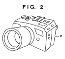
- a mock-up 11 is a full-scale model of a camera in this embodiment, as shown in Fig. 2 , and the observer can freely pick it up.
- This mock-up 11 is a full-scale model of a camera as an industrial product, but it has a solid-color outer appearance and roughly imitates only the outer shape.
- the weight of the mock-up 11 is substantially equal to that of the actual product to offer a feeling upon operating the actual product to the observer.
- the mock-up 11 incorporates a position and orientation sensor 12.
- the position and orientation sensor 12 is fixed or incorporated at a predetermined position in the mock-up 11, and the positional relationship between the mock-up 11 and position and orientation sensor 12 is constant. For this reason, the position and orientation of the mock-up can be calculated from position/orientation information of the position and orientation sensor 12.
- the position and orientation information measured by the position and orientation sensor 12 is transmitted to the position and orientation measurement unit 105 of the PC 101.
- the position and orientation measurement unit 105 receives position and orientation information from the position and orientation sensor 36 fixed to the HMD, and the position and orientation sensor 12 incorporated in the mock-up.
- the position and orientation measurement unit 105 executes processes such as coordinate conversion and the like of the received position and orientation information to calculate the viewpoint position and orientation of the observer and the position and orientation of the mock-up 11 on a world coordinate system, and transits them to the 3DCG model generation unit 107.
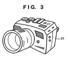
- the 3DCG model generation unit 107 generates 3DCG models (e.g., a CG camera 21 shown in Fig. 3 ) to be respectively observed from the viewpoints of the right and left eyes of the observer on the basis of the two pieces of received position and orientation information.
- the unit 107 transmits the generated 3DCG models viewed from the right and left viewpoints to the image composition unit 109.
- Fig. 3 illustrates the superimposed state of the CG camera 21 onto the mock-up 11 using the MR technique.
- the CG camera 21 is a 3DCG model of the camera and has a real size.
- the CG camera 21 has the same shape and size as those of the mock-up 11, and they exactly overlap each other when the CG camera 21 is superimposed to match the position and orientation of the mock-up 11.
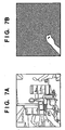
- the object region extraction unit 106 compares color information of each pixel of each of actually captured images ( Fig. 7A ) captured by the video capture devices A 102 and B 103 with color information of an object, which is registered in advance in the object color information registration unit 110, and determines that a pixel which has a color that matches or is close to the registered color information belongs to an object region. Such determination process is repeated for respective pixels, and right and left object region images are transmitted to the image composition unit 109 in the form of a binary image ( Fig. 7B ), which is generated so that a pixel included in the object is 1 and a pixel which is not included in the object is 0 as the determination result.
- a binary image Fig. 7B
- the object is an observer's hand
- the object color information registration unit 110 registers information associated with a flesh color sampled in advance.
- step S1101 actually captured images from the video camera devices B 103 and A 102 are respectively transferred to right- and left-eye frame buffers (not shown) as image memories for image display.
- step S1102 the object region images generated by the object region extraction unit 106 are transferred to right- and left-eye stencil buffers (not shown) as image memories for a mask process.
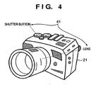
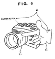
- the annotation generation unit 108 generates annotations 41 shown in, e.g., Fig. 4 as CG images, and overwrites them on the received right- and left-eye superimposed images to point to predetermined positions (shutter button and lens in Fig. 4 ) of the 3DCG image.
- the annotations 41 are text data which are located on the 3D virtual space and have given positional relationships with the CG camera 21, and their positions and orientations change in conjunction with the CG camera 21 as if they were components of the CG camera 21. Since the annotations are overwritten finally, the observer can visually observe the annotations even when the annotations overlap the object region.
- An exemplary method of displaying the annotations 41 to point to correct positions of the 3DCG image is now described. First, acquiring the position and orientation information of the mock-up and the observer from the position and orientation measurement unit 105. Next, determining annotation display positions based on these position and orientation information and positional relationship between the annotations 41 and the CG camera 21. Then, overwriting a text corresponding to the annotations 41 on the determined display positions of an image output from the image composition unit 109.
- a displayed image e.g., as shown in Fig. 6 can be easily generated with a simple structure.
- acquiring image coordinate positions of the shutter button and lens in the 3DCG image from the 3DCG model generation unit 107 and then generating annotations to point to these image coordinate positions, and the like can be adopted.
- the annotation generation unit 108 transmits the mixed reality space images overwritten with the annotations to the display control unit 104.
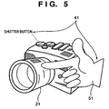
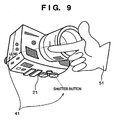
- Fig. 5 shows the display state upon displaying annotations shown in Fig. 4 using the conventional method.
- Fig. 5 shows a display example in which the observer's hand is extracted as an object region which is used as a mask, so as to prevent the observer's hand from being occluded by the CG camera 21.
- the CG camera 21 is occluded by the observer's hand 51 to express a state wherein the CG camera 21 is located at the far side of the hand position.
- the annotation 41 for the lens is occluded and cannot be read.
- the annotations are overwritten finally, even when the object region (i.e., the observer's hand) is located at the position shown in Fig. 5 , the annotation is displayed on the hand, and the observer can read that annotation. That is, the observer can read the annotation independently of the location of the object region while making natural display in consideration of the depth.
- the display control unit 104 transmits right- and left-eye mixed reality space images to the video display unit 35 of the video see-through HMD 32, and the video display unit 35 receives and displays these images.
- the annotations are always displayed on a plane (display plane) perpendicular to a straight line from the viewpoint of the observer to the mock-up in the same direction as the orientation of the observer. In this manner, the annotations are readably displayed for the observer irrespective of the orientations of the mock-up and observer.
- the position and orientation sensor 12 provided to the mock-up 11 may detect its direction, and annotation display may be made in accordance with the detected direction of the mock-up 11. For example, in this embodiment, when the front surface of the camera (a surface that the object faces) faces the observer, annotations for the range viewed from the front surface side can be displayed; when the back surface faces the observer, annotations for the range viewed from the back surface side can be displayed.
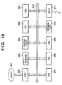
- Fig. 10 is a block diagram showing an example of the arrangement of a computer which can be used as the PC 101 in this embodiment.
- a display 201 displays information of data which is being processed by an application program, various message menus, and the like, and comprises a CRT (Cathode Ray Tube), LCD (Liquid Crystal Display), or the like.
- a CRTC 202 as a display controller makes screen display control of the display 201.
- a keyboard 203 and pointing device 204 are used to input characters, and to designate icons, buttons, and the like on a GUI (Graphical User Interface).
- a CPU 205 controls the overall computer.
- a ROM (Read Only Memory) 206 stores programs to be executed by the CPU 205, parameters, and the like.
- a RAM (Random Access Memory) 207 is used as a work area when the CPU 205 executes various programs, a temporary save area in an error process, and the like.
- a hard disk drive (HDD) 208 and removable media drive (RMD) 209 serve as external storage devices.
- the removable media drive is a device for reading/writing information from/on or reading information from a removable recording medium.
- the removable media drive may comprise a flexible disk drive, optical disk drive, magnetooptical disk drive, or memory card reader, or may comprise a removable HDD or the like.
- programs e.g., application programs, and error processing programs
- an OS other application programs such as a browser and the like, data, libraries, and the like are stored in one or more of the ROM 206, HDD 208, and (recording medium of) RMD 209 according to their purposes.
- An expansion slot 210 is an expansion card slot complying with, e.g., the PCI (Peripheral Component Interconnect) bus standard, and can connect various expansion boards such as a video capture board, sound board, GPIB board, and the like.
- PCI Peripheral Component Interconnect
- a network interface 211 is used to connect the computer to a computer network.
- a bus 212 includes an address bus, data bus, and control bus, and interconnects the aforementioned units.
- the computer also has a serial interface such as RS-232C, RS-422, USB (Universal Serial Bus), IEEE1394, or the like, and a parallel interface such as IEEE1284 or the like and can connect external devices such as a modem, printer, and the like.
- Such general-purpose computer can communicate with another device on the computer network or public telephone network using the OS, required driver software, and the like, and a router (including a dial-up router) connected as needed via the network interface 211 or a modem, TA, or the like connected via the serial interface.
- a router including a dial-up router
- the video capture devices A 102 and B 103, and the position and orientation measurement unit 105 are implemented as, e.g., a video capture board and an interface board with the position and orientation sensors 12 and 36, which are connected to the expansion slot, and their control programs.
- the object region extraction unit 106, 3DCG model generation unit 107, annotation generation unit 108, and image composition unit 109 can be implemented when the CPU 105 executes software.
- the display control unit 104 is implemented by the CRTC 201.
- the mixed reality system including the HMD and mock-up has been explained to help easy understanding, but they are not always required.
- Components associated with acquisition of a real space image, display of a mixed reality space image, and position and orientation measurements of the mock-up and observer's viewpoint are not indispensable, and acquisition and display processes of such images and information may be done by an external apparatus.
- the object region is detected by comparing a color registered in the object color information registration unit with each pixel in the image.
- a color region which is different from the color of the mock-up may be extracted from a mock-up portion in the actually captured image and may be determined as an object region, or an object region may be obtained by the aforementioned method using a color of that region as the object color information.
- the aforementioned embodiment includes a mock-up system exploiting mixed reality.
- the present invention is not limited to an application that displays a virtual space image which represents the outer appearance of a real object, but it can be applied to arbitrary other applications and mixed reality systems in which virtual space images to be displayed include those to be displayed in consideration of the depth (occlusion) and those which need not undergo such control. Therefore, a virtual space image which is to be displayed without considering any occlusion is not limited to an annotation but may be an arbitrary virtual space image.
- the object is the observer's hand, but may be an instrument to be operated by the observer, other body regions, or a real object other than the observer.
- the PC 101 is configured by a single device.
- the equivalent functions may be implemented by a system including a plurality of devices.
- an embodiment includes a case wherein the equivalent functions are achieved by supplying a software program that implements the functions of the aforementioned embodiments directly from a recording medium or using wired/wireless communications to a system or apparatus having a computer that can execute the program, and executing the supplied program by the computer of that system or apparatus.
- the program code itself supplied to and installed in the computer to implement the functional processes and a carrier (such as a storage medium or signal) carrying the program code constitute embodiments of the present invention.
- program is not particularly limited, and an object code, a program to be executed by an interpreter, script data to be supplied to an OS, and the like may be used as along as they have the program function.
- the storage medium for supplying the program for example, magnetic recording media such as a flexible disk, hard disk, magnetic tape, and the like, optical/magnetooptical storage media such as an MO, CD-ROM, CD-R, CD-RW, DVD-ROM, DVD-R, DVD-RW, and the like, a nonvolatile semiconductor memory, and so forth may be used.
- a server on a computer network may store a data file (program data file), a compressed file including an automatic installation function, or the like, and the program data file may be downloaded to a client computer which establishes connection to the server.
- the program data file may be segmented into a plurality of segment files, which may be allocated on different servers.
- the server apparatus makes a plurality of users download the program data file for implementing the functional process of an embodiment on a computer.
- a storage medium such as a CD-ROM or the like, which stores the encrypted program may be delivered to the user, the user who has cleared a predetermined condition may be allowed to download key information that is used to decrypt the program from a home page via the Internet, and the encrypted program may be executed using that key information to be installed on a computer, thus implementing an embodiment.
- the functions of the aforementioned embodiments may be implemented not only by executing the readout program code by the computer but also by some or all of actual processing operations executed by an OS or the like running on the computer on the basis of an instruction of that program.
- the functions of the aforementioned embodiments may be implemented by some or all of actual processes executed by a CPU or the like arranged in a function extension board or a function extension unit, which is inserted in or connected to the computer, after the program read out from the recording medium is written in a memory of the extension board or unit.
Landscapes
- Engineering & Computer Science (AREA)
- Multimedia (AREA)
- Signal Processing (AREA)
- Physics & Mathematics (AREA)
- General Physics & Mathematics (AREA)
- Theoretical Computer Science (AREA)
- Computer Graphics (AREA)
- Computer Hardware Design (AREA)
- General Engineering & Computer Science (AREA)
- Software Systems (AREA)
- Computer Vision & Pattern Recognition (AREA)
- Processing Or Creating Images (AREA)
Claims (7)
- Verfahren zum Generieren eines Mixedrealityraumbilds, erzeugt durch Überlagern eines Virtuellraumbilds auf ein erstes Realraumbild, welches durch Aufnehmen eines ersten Realraumobjekts (11) mit Hilfe einer Bildaufnahmeeinrichtung (33, 34) erhalten wird, umfassend:einen Erfassungsschritt (105) zum Erfassen einer Position und Orientierung des ersten Realraumobjekts (11) im Realraum und einer Position und Orientierung der Aufnahmeeinrichtung (33, 34) im Realraum;einen ersten Generierschritt (107) zum Generieren eines ersten virtuellen Bilds (21), welches in Form, Größe und Orientierung mit dem ersten Realraumobjekt in dessen Erscheinungsform im ersten Realraumbild übereinstimmt, wobei die Positionen und Orientierungen des ersten Objekts und der Bildaufnahmeeinrichtung berücksichtigt werden;einen zweiten Generierschritt (108) zum Generieren eines Kommentierungsbilds, welches eine Kommentierung des ersten Objekts wiedergibt;einen Extraktionsschritt (106), um aus dem ersten Realraumbild eine einem zweiten Objekt (51) im Realraum entsprechende Bildzone zu bestimmen;einen ersten Bildüberlagerungsschritt (109) zum Überlagern (S1103) des ersten virtuellen Bilds (21) auf das erste Realraumbild an Pixelstellen, die nicht in der Bildzone enthalten sind; undeinen zweiten Bildüberlagerungsschritt (108) zum Überlagern des Kommentierungsbilds auf das im ersten Bildüberlagerungsschritt generierte Überlagerungsbild, wobei die Position, an der das Kommentierungsbild eingerichtet wird, abhängt von der Position und der Orientierung des ersten Realraumobjekts (11).
- Verfahren nach Anspruch 1, dadurch gekennzeichnet, dass das zweite Objekt eine Hand eines Betrachters des Mixedrealityraumbilds ist.
- Verfahren nach Anspruch 1, wobei das erste Objekt ein Modell ist.
- Vorrichtung zum Generieren eines Mixedrealityraumbilds, erzeugt durch Überlagern von Virtuellraumbildern auf ein erstes Realraumbild, welches erhalten wird durch Verwendung einer Aufnahmeeinrichtung, um ein erstes Realraumobjekt (11) aufzunehmen, umfassend:eine Positions- und Orientierungsmesseinheit (105) zum Erfassen einer Position und Orientierung des ersten Realraumobjekts (11) im Realraum und einer Position und Orientierung der Aufnahmeeinrichtung (33, 34) im Realraum,einen ersten Generator (107), der ein erstes virtuelles Bild (21) generiert, welches in Form, Größe und Orientierung mit dem ersten Realraumobjekt in dessen Erscheinungsform im ersten Realraumbild übereinstimmt, wobei die Positionen und Orientierung des ersten Objekts und der Bildaufnahmeeinrichtung berücksichtigt werden;einen zweiten Generator (108) zum Generieren eines Kommentierungsbilds, welches eine Kommentierung des ersten Objekts wiedergibt;eine Objektzonen-Extraktionseinheit (106) zum Bestimmen einer Bildzone entsprechend einem zweiten Objekt (51) im Realraum aus dem ersten Realraumbild,ein erstes Bildüberlagerungsmittel (109) zum Überlagern (S1103) des ersten virtuellen Bilds (21) auf das erste Realraumbild an Pixelstellen, die nicht in der Bildzone enthalten sind, um ein Überlagerungsbild zu erzeugen; undein zweites Bildüberlagerungsmittel (108) zum Überlagern des Kommentierungsbilds auf das vom ersten Überlagerungsmittel generierte Überlagerungsbild, wobei die Position, an der das Kommentierungsbild eingerichtet wird, abhängt von der Position und der Orientierung des ersten Realraumobjekts (11).
- Vorrichtung nach Anspruch 4, umfassend:eine am Kopf zu tragende Anzeigeeinrichtung zum Anzeigen des vom zweiten Bildüberlagerungsmittel ausgegebenen Bilds, wobei die Aufnahmeeinrichtung sich an der am Kopf zu tragenden Anzeigeeinrichtung befindet.
- Vorrichtung nach Anspruch 4, wobei das zweite Objekt eine Hand eines Betrachters des Mixedrealityraumbilds ist.
- System zum Generieren eines Mixedrealityraumbilds, umfassend die Vorrichtung nach Anspruch 4 und ein Modell als das erste Realraumobjekt.
Applications Claiming Priority (2)
| Application Number | Priority Date | Filing Date | Title |
|---|---|---|---|
| JP2003341629 | 2003-09-30 | ||
| JP2003341629A JP4401728B2 (ja) | 2003-09-30 | 2003-09-30 | 複合現実空間画像生成方法及び複合現実感システム |
Publications (2)
| Publication Number | Publication Date |
|---|---|
| EP1521216A1 EP1521216A1 (de) | 2005-04-06 |
| EP1521216B1 true EP1521216B1 (de) | 2012-01-11 |
Family
ID=34309073
Family Applications (1)
| Application Number | Title | Priority Date | Filing Date |
|---|---|---|---|
| EP04255974A Expired - Lifetime EP1521216B1 (de) | 2003-09-30 | 2004-09-29 | Verfahren und System zur Erzeugung gemischt realer und virtueller Bilder. |
Country Status (4)
| Country | Link |
|---|---|
| US (1) | US7589747B2 (de) |
| EP (1) | EP1521216B1 (de) |
| JP (1) | JP4401728B2 (de) |
| CN (1) | CN100479530C (de) |
Families Citing this family (61)
| Publication number | Priority date | Publication date | Assignee | Title |
|---|---|---|---|---|
| US7834890B2 (en) | 2003-10-17 | 2010-11-16 | Canon Kabushiki Kaisha | Information processing method and image processing method |
| JP4522129B2 (ja) * | 2004-03-31 | 2010-08-11 | キヤノン株式会社 | 画像処理方法および画像処理装置 |
| JP4227561B2 (ja) * | 2004-06-03 | 2009-02-18 | キヤノン株式会社 | 画像処理方法、画像処理装置 |
| DE102005009437A1 (de) * | 2005-03-02 | 2006-09-07 | Kuka Roboter Gmbh | Verfahren und Vorrichtung zum Einblenden von AR-Objekten |
| JP4726194B2 (ja) * | 2005-04-01 | 2011-07-20 | キヤノン株式会社 | キャリブレーション方法及び装置 |
| JP4667111B2 (ja) * | 2005-04-21 | 2011-04-06 | キヤノン株式会社 | 画像処理装置、画像処理方法 |
| EP1720131B1 (de) * | 2005-05-03 | 2009-04-08 | Seac02 S.r.l. | Augmented-Reality-System mit Identifizierung der realen Markierung des Objekts |
| US9648907B2 (en) * | 2005-05-31 | 2017-05-16 | Philip Morris Usa Inc. | Virtual reality smoking system |
| CN100590660C (zh) * | 2005-07-15 | 2010-02-17 | 佳能株式会社 | 图像处理设备和设计方法 |
| JP4914123B2 (ja) | 2005-07-15 | 2012-04-11 | キヤノン株式会社 | 画像処理装置及び方法 |
| US8797352B2 (en) * | 2005-08-09 | 2014-08-05 | Total Immersion | Method and devices for visualising a digital model in a real environment |
| US7606392B2 (en) * | 2005-08-26 | 2009-10-20 | Sony Corporation | Capturing and processing facial motion data |
| JP4958497B2 (ja) * | 2006-08-07 | 2012-06-20 | キヤノン株式会社 | 位置姿勢測定装置及び位置姿勢測定方法、複合現実感提示システム、コンピュータプログラム及び記憶媒体 |
| EP1887526A1 (de) * | 2006-08-11 | 2008-02-13 | Seac02 S.r.l. | Videosystem mit digital erweiterter Realität |
| JP4909176B2 (ja) * | 2007-05-23 | 2012-04-04 | キヤノン株式会社 | 複合現実感提示装置及びその制御方法、コンピュータプログラム |
| JP4989383B2 (ja) * | 2007-09-10 | 2012-08-01 | キヤノン株式会社 | 情報処理装置、情報処理方法 |
| US8769437B2 (en) | 2007-12-12 | 2014-07-01 | Nokia Corporation | Method, apparatus and computer program product for displaying virtual media items in a visual media |
| US9354853B2 (en) * | 2008-07-02 | 2016-05-31 | Hewlett-Packard Development Company, L.P. | Performing administrative tasks associated with a network-attached storage system at a client |
| EP3220616B1 (de) | 2008-07-15 | 2019-09-04 | Immersion Corporation | Systeme und verfahren zur haptischen nachrichtenübertragung |
| US20100214243A1 (en) * | 2008-07-15 | 2010-08-26 | Immersion Corporation | Systems and Methods For Interpreting Physical Interactions With A Graphical User Interface |
| JP2010033367A (ja) * | 2008-07-29 | 2010-02-12 | Canon Inc | 情報処理装置及び情報処理方法 |
| JP5332576B2 (ja) * | 2008-12-11 | 2013-11-06 | 富士ゼロックス株式会社 | 情報処理装置、情報処理システム及びプログラム |
| JP4848001B2 (ja) * | 2008-12-18 | 2011-12-28 | 株式会社ソニー・コンピュータエンタテインメント | 画像処理装置および画像処理方法 |
| JP5232619B2 (ja) * | 2008-12-18 | 2013-07-10 | 株式会社ソニー・コンピュータエンタテインメント | 検査装置および検査方法 |
| JP5793426B2 (ja) * | 2009-01-29 | 2015-10-14 | イマージョン コーポレーションImmersion Corporation | グラフィカルユーザインターフェースとの物理的相互作用を解釈するためのシステムと方法 |
| US8405658B2 (en) * | 2009-09-14 | 2013-03-26 | Autodesk, Inc. | Estimation of light color and direction for augmented reality applications |
| KR101082285B1 (ko) * | 2010-01-29 | 2011-11-09 | 주식회사 팬택 | 증강 현실 제공 단말기 및 방법 |
| US8947455B2 (en) | 2010-02-22 | 2015-02-03 | Nike, Inc. | Augmented reality design system |
| US9122707B2 (en) | 2010-05-28 | 2015-09-01 | Nokia Technologies Oy | Method and apparatus for providing a localized virtual reality environment |
| US9710554B2 (en) | 2010-09-23 | 2017-07-18 | Nokia Technologies Oy | Methods, apparatuses and computer program products for grouping content in augmented reality |
| US20120293546A1 (en) * | 2011-05-18 | 2012-11-22 | Tomi Lahcanski | Augmented-reality mobile communicator with orientation |
| KR101795644B1 (ko) | 2011-07-29 | 2017-11-08 | 휴렛-팩커드 디벨롭먼트 컴퍼니, 엘.피. | 투영 캡쳐 시스템, 투영 캡쳐 프로그래밍, 및 투영 캡쳐 방법 |
| KR101773988B1 (ko) | 2011-07-29 | 2017-09-01 | 휴렛-팩커드 디벨롭먼트 컴퍼니, 엘.피. | 시각적 계층화 시스템 및 시각적 계층화 방법 |
| US9521276B2 (en) | 2011-08-02 | 2016-12-13 | Hewlett-Packard Development Company, L.P. | Portable projection capture device |
| US9606992B2 (en) * | 2011-09-30 | 2017-03-28 | Microsoft Technology Licensing, Llc | Personal audio/visual apparatus providing resource management |
| US8711118B2 (en) | 2012-02-15 | 2014-04-29 | Immersion Corporation | Interactivity model for shared feedback on mobile devices |
| US8493354B1 (en) | 2012-08-23 | 2013-07-23 | Immersion Corporation | Interactivity model for shared feedback on mobile devices |
| JP5977544B2 (ja) | 2012-03-09 | 2016-08-24 | キヤノン株式会社 | 情報処理装置、情報処理方法 |
| JP5975685B2 (ja) | 2012-03-09 | 2016-08-23 | キヤノン株式会社 | 情報処理装置、情報処理方法 |
| JP6000579B2 (ja) | 2012-03-09 | 2016-09-28 | キヤノン株式会社 | 情報処理装置、情報処理方法 |
| US8570296B2 (en) | 2012-05-16 | 2013-10-29 | Immersion Corporation | System and method for display of multiple data channels on a single haptic display |
| US10387484B2 (en) | 2012-07-24 | 2019-08-20 | Symbol Technologies, Llc | Mobile device for displaying a topographical area defined by a barcode |
| GB2499694B8 (en) * | 2012-11-09 | 2017-06-07 | Sony Computer Entertainment Europe Ltd | System and method of image reconstruction |
| EP3219097A4 (de) | 2014-11-13 | 2018-06-27 | Hewlett-Packard Development Company, L.P. | Bildprojektion |
| US10127331B2 (en) * | 2014-12-15 | 2018-11-13 | The Boeing Company | 3D models utilizing 3D markers to indicate engineering requirements |
| RU2597462C1 (ru) * | 2015-07-17 | 2016-09-10 | Виталий Витальевич Аверьянов | Способ отображения объекта на пространственной модели |
| US10222958B2 (en) * | 2016-07-22 | 2019-03-05 | Zeality Inc. | Customizing immersive media content with embedded discoverable elements |
| US10068380B2 (en) * | 2016-11-17 | 2018-09-04 | Adobe Systems Incorporated | Methods and systems for generating virtual reality environments from electronic documents |
| US11054894B2 (en) | 2017-05-05 | 2021-07-06 | Microsoft Technology Licensing, Llc | Integrated mixed-input system |
| US11023109B2 (en) | 2017-06-30 | 2021-06-01 | Microsoft Techniogy Licensing, LLC | Annotation using a multi-device mixed interactivity system |
| US10895966B2 (en) | 2017-06-30 | 2021-01-19 | Microsoft Technology Licensing, Llc | Selection using a multi-device mixed interactivity system |
| JP6785983B2 (ja) * | 2017-09-25 | 2020-11-18 | 三菱電機株式会社 | 情報表示装置及び方法、並びにプログラム及び記録媒体 |
| US11176747B2 (en) * | 2017-10-30 | 2021-11-16 | Sony Corporation | Information processing apparatus and information processing method |
| CN110118870B (zh) * | 2018-02-06 | 2023-04-07 | 深圳市帝迈生物技术有限公司 | 血细胞分析仪及运行方法 |
| US11284646B2 (en) | 2018-03-22 | 2022-03-29 | Altria Client Services Llc | Augmented reality and/or virtual reality based e-vaping device vapor simulation systems and methods |
| KR102581146B1 (ko) * | 2018-11-23 | 2023-09-21 | 삼성전자주식회사 | 디스플레이 장치 및 그 제어 방법 |
| CN113272873B (zh) * | 2018-12-20 | 2025-06-27 | 三星电子株式会社 | 用于增强现实的方法和设备 |
| KR102447537B1 (ko) | 2019-10-10 | 2022-09-26 | 주식회사 케이티앤지 | 흡연 시스템 |
| CN111833458B (zh) * | 2020-06-30 | 2023-06-23 | 北京市商汤科技开发有限公司 | 图像显示方法及装置、设备、计算机可读存储介质 |
| US12437251B2 (en) | 2022-03-04 | 2025-10-07 | International Business Machines Corporation | Systems, apparatus, program products, and methods for intelligent management of asset workflows |
| JP2024124184A (ja) * | 2023-03-02 | 2024-09-12 | キヤノン株式会社 | 画像処理装置および画像処理方法、ならびにバーチャルスタジオシステム |
Citations (1)
| Publication number | Priority date | Publication date | Assignee | Title |
|---|---|---|---|---|
| EP0899690A2 (de) * | 1997-09-01 | 1999-03-03 | Mixed Reality Systems Laboratory Inc. | Vorrichtung und Verfahren zur Darstellung gemischter virtueller Realität, gemeinsam von mehreren Bedienungspersonen genutzt |
Family Cites Families (28)
| Publication number | Priority date | Publication date | Assignee | Title |
|---|---|---|---|---|
| US5815411A (en) * | 1993-09-10 | 1998-09-29 | Criticom Corporation | Electro-optic vision system which exploits position and attitude |
| JPH0816102A (ja) | 1994-06-30 | 1996-01-19 | Matsushita Electric Ind Co Ltd | 車載用地図表示装置 |
| US5892554A (en) * | 1995-11-28 | 1999-04-06 | Princeton Video Image, Inc. | System and method for inserting static and dynamic images into a live video broadcast |
| US6094625A (en) * | 1997-07-03 | 2000-07-25 | Trimble Navigation Limited | Augmented vision for survey work and machine control |
| JP3486536B2 (ja) | 1997-09-01 | 2004-01-13 | キヤノン株式会社 | 複合現実感提示装置および方法 |
| IL149543A0 (en) | 1999-11-08 | 2002-11-10 | Mirage Systems Inc | Method and apparatus for real time insertion of images into video |
| US6618425B1 (en) * | 1999-11-17 | 2003-09-09 | Cymer, Inc. | Virtual laser operator |
| US20020191004A1 (en) * | 2000-08-09 | 2002-12-19 | Ebersole John Franklin | Method for visualization of hazards utilizing computer-generated three-dimensional representations |
| US6803928B2 (en) * | 2000-06-06 | 2004-10-12 | Fraunhofer-Gesellschaft Zur Foerderung Der Angewandten Forschung E.V. | Extended virtual table: an optical extension for table-like projection systems |
| US6977630B1 (en) * | 2000-07-18 | 2005-12-20 | University Of Minnesota | Mobility assist device |
| JP2002095535A (ja) | 2000-09-25 | 2002-04-02 | Toshio Takayama | マグネット(磁石)飛散防止板 |
| US6954498B1 (en) * | 2000-10-24 | 2005-10-11 | Objectvideo, Inc. | Interactive video manipulation |
| JP2002157607A (ja) * | 2000-11-17 | 2002-05-31 | Canon Inc | 画像生成システム、画像生成方法および記憶媒体 |
| JP3635051B2 (ja) | 2001-02-01 | 2005-03-30 | 株式会社ソニー・コンピュータエンタテインメント | 画像生成方法及び装置、画像処理プログラムを記録した記録媒体、画像処理プログラム |
| JP2003050132A (ja) | 2001-08-06 | 2003-02-21 | Alpine Electronics Inc | ナビゲーション装置 |
| JP4445182B2 (ja) | 2002-03-29 | 2010-04-07 | パイオニア株式会社 | スピーカ装置 |
| JP4136420B2 (ja) | 2002-03-29 | 2008-08-20 | キヤノン株式会社 | 情報処理方法および装置 |
| DE10236221C1 (de) * | 2002-08-07 | 2003-11-20 | Siemens Ag | Verfahren und Vorrichtung zur Anzeige von Navigationsinformationen für ein Fahrzeug |
| JP2003203245A (ja) | 2002-10-03 | 2003-07-18 | Ffc:Kk | 図面表示処理装置 |
| US6867753B2 (en) * | 2002-10-28 | 2005-03-15 | University Of Washington | Virtual image registration in augmented display field |
| JP4356983B2 (ja) * | 2004-02-10 | 2009-11-04 | キヤノン株式会社 | 画像処理方法、画像処理装置 |
| US7474318B2 (en) * | 2004-05-28 | 2009-01-06 | National University Of Singapore | Interactive system and method |
| US20050285878A1 (en) * | 2004-05-28 | 2005-12-29 | Siddharth Singh | Mobile platform |
| US20060028400A1 (en) * | 2004-08-03 | 2006-02-09 | Silverbrook Research Pty Ltd | Head mounted display with wave front modulator |
| DE102005061211B4 (de) * | 2004-12-22 | 2023-04-06 | Abb Schweiz Ag | Verfahren zum Erzeugen einer Mensch-Maschine-Benutzer-Oberfläche |
| US9648907B2 (en) * | 2005-05-31 | 2017-05-16 | Philip Morris Usa Inc. | Virtual reality smoking system |
| US20070035563A1 (en) * | 2005-08-12 | 2007-02-15 | The Board Of Trustees Of Michigan State University | Augmented reality spatial interaction and navigational system |
| JP4785662B2 (ja) * | 2005-10-03 | 2011-10-05 | キヤノン株式会社 | 情報処理装置、情報処理方法 |
-
2003
- 2003-09-30 JP JP2003341629A patent/JP4401728B2/ja not_active Expired - Fee Related
-
2004
- 2004-09-29 EP EP04255974A patent/EP1521216B1/de not_active Expired - Lifetime
- 2004-09-29 US US10/951,684 patent/US7589747B2/en not_active Expired - Fee Related
- 2004-09-30 CN CNB2004100810645A patent/CN100479530C/zh not_active Expired - Fee Related
Patent Citations (1)
| Publication number | Priority date | Publication date | Assignee | Title |
|---|---|---|---|---|
| EP0899690A2 (de) * | 1997-09-01 | 1999-03-03 | Mixed Reality Systems Laboratory Inc. | Vorrichtung und Verfahren zur Darstellung gemischter virtueller Realität, gemeinsam von mehreren Bedienungspersonen genutzt |
Also Published As
| Publication number | Publication date |
|---|---|
| JP4401728B2 (ja) | 2010-01-20 |
| JP2005107971A (ja) | 2005-04-21 |
| CN1604659A (zh) | 2005-04-06 |
| US7589747B2 (en) | 2009-09-15 |
| EP1521216A1 (de) | 2005-04-06 |
| CN100479530C (zh) | 2009-04-15 |
| US20050179617A1 (en) | 2005-08-18 |
Similar Documents
| Publication | Publication Date | Title |
|---|---|---|
| EP1521216B1 (de) | Verfahren und System zur Erzeugung gemischt realer und virtueller Bilder. | |
| US8055061B2 (en) | Method and apparatus for generating three-dimensional model information | |
| US7728852B2 (en) | Image processing method and image processing apparatus | |
| EP1708139B1 (de) | Kalibrierverfahren und -vorrichtung | |
| JP4933406B2 (ja) | 画像処理装置、画像処理方法 | |
| JP4434890B2 (ja) | 画像合成方法及び装置 | |
| JP4227561B2 (ja) | 画像処理方法、画像処理装置 | |
| US7782320B2 (en) | Information processing method and information processing apparatus | |
| JP4137078B2 (ja) | 複合現実感情報生成装置および方法 | |
| US20060092131A1 (en) | Image processing method and apparatus | |
| EP1744280B1 (de) | Vorrichtung und Verfahren zur Informationsverarbeitung | |
| JP2016122392A (ja) | 情報処理装置、情報処理システム、その制御方法及びプログラム | |
| JP6775957B2 (ja) | 情報処理装置、情報処理方法、プログラム | |
| EP0817133B1 (de) | Objektvisualisierung im Kontext | |
| JP4847195B2 (ja) | 画像からの色情報の取得方法 | |
| JP4208601B2 (ja) | 表示制御方法、及び表示制御装置 | |
| JP4834424B2 (ja) | 情報処理装置、情報処理方法、及びプログラム | |
| JP2016115230A (ja) | 情報処理装置、情報処理システム、その制御方法及びプログラム | |
| JP7279113B2 (ja) | 画像処理装置、画像処理方法、コンピュータプログラム | |
| JP4217661B2 (ja) | 画像処理方法、画像処理装置 | |
| JP2005251118A (ja) | 画像処理方法、画像処理装置 | |
| KR20180071492A (ko) | 키넥트 센서를 이용한 실감형 콘텐츠 서비스 시스템 | |
| JP5647813B2 (ja) | 映像提示システム、プログラム及び記録媒体 | |
| JP2015121892A (ja) | 画像処理装置、画像処理方法 | |
| JP7479978B2 (ja) | 内視映像表示システム、内視映像表示装置及び内視映像表示方法 |
Legal Events
| Date | Code | Title | Description |
|---|---|---|---|
| PUAI | Public reference made under article 153(3) epc to a published international application that has entered the european phase |
Free format text: ORIGINAL CODE: 0009012 |
|
| AK | Designated contracting states |
Kind code of ref document: A1 Designated state(s): AT BE BG CH CY CZ DE DK EE ES FI FR GB GR HU IE IT LI LU MC NL PL PT RO SE SI SK TR |
|
| AX | Request for extension of the european patent |
Extension state: AL HR LT LV MK |
|
| 17P | Request for examination filed |
Effective date: 20050823 |
|
| AKX | Designation fees paid |
Designated state(s): DE FR GB IT NL |
|
| 17Q | First examination report despatched |
Effective date: 20071123 |
|
| GRAC | Information related to communication of intention to grant a patent modified |
Free format text: ORIGINAL CODE: EPIDOSCIGR1 |
|
| GRAJ | Information related to disapproval of communication of intention to grant by the applicant or resumption of examination proceedings by the epo deleted |
Free format text: ORIGINAL CODE: EPIDOSDIGR1 |
|
| GRAP | Despatch of communication of intention to grant a patent |
Free format text: ORIGINAL CODE: EPIDOSNIGR1 |
|
| GRAP | Despatch of communication of intention to grant a patent |
Free format text: ORIGINAL CODE: EPIDOSNIGR1 |
|
| GRAS | Grant fee paid |
Free format text: ORIGINAL CODE: EPIDOSNIGR3 |
|
| REG | Reference to a national code |
Ref country code: DE Ref legal event code: R079 Ref document number: 602004036067 Country of ref document: DE Free format text: PREVIOUS MAIN CLASS: G06T0017400000 Ipc: G06T0019200000 |
|
| GRAA | (expected) grant |
Free format text: ORIGINAL CODE: 0009210 |
|
| AK | Designated contracting states |
Kind code of ref document: B1 Designated state(s): DE FR GB IT NL |
|
| REG | Reference to a national code |
Ref country code: GB Ref legal event code: FG4D |
|
| RIC1 | Information provided on ipc code assigned before grant |
Ipc: H04N 5/272 20060101ALI20111206BHEP Ipc: G06T 19/20 20110101AFI20111206BHEP |
|
| REG | Reference to a national code |
Ref country code: DE Ref legal event code: R096 Ref document number: 602004036067 Country of ref document: DE Effective date: 20120308 |
|
| REG | Reference to a national code |
Ref country code: NL Ref legal event code: VDEP Effective date: 20120111 |
|
| PG25 | Lapsed in a contracting state [announced via postgrant information from national office to epo] |
Ref country code: NL Free format text: LAPSE BECAUSE OF FAILURE TO SUBMIT A TRANSLATION OF THE DESCRIPTION OR TO PAY THE FEE WITHIN THE PRESCRIBED TIME-LIMIT Effective date: 20120111 |
|
| PLBE | No opposition filed within time limit |
Free format text: ORIGINAL CODE: 0009261 |
|
| STAA | Information on the status of an ep patent application or granted ep patent |
Free format text: STATUS: NO OPPOSITION FILED WITHIN TIME LIMIT |
|
| PG25 | Lapsed in a contracting state [announced via postgrant information from national office to epo] |
Ref country code: IT Free format text: LAPSE BECAUSE OF FAILURE TO SUBMIT A TRANSLATION OF THE DESCRIPTION OR TO PAY THE FEE WITHIN THE PRESCRIBED TIME-LIMIT Effective date: 20120111 |
|
| 26N | No opposition filed |
Effective date: 20121012 |
|
| REG | Reference to a national code |
Ref country code: DE Ref legal event code: R097 Ref document number: 602004036067 Country of ref document: DE Effective date: 20121012 |
|
| REG | Reference to a national code |
Ref country code: FR Ref legal event code: PLFP Year of fee payment: 13 |
|
| REG | Reference to a national code |
Ref country code: FR Ref legal event code: PLFP Year of fee payment: 14 |
|
| PGFP | Annual fee paid to national office [announced via postgrant information from national office to epo] |
Ref country code: FR Payment date: 20170928 Year of fee payment: 14 Ref country code: GB Payment date: 20170929 Year of fee payment: 14 |
|
| PGFP | Annual fee paid to national office [announced via postgrant information from national office to epo] |
Ref country code: DE Payment date: 20171130 Year of fee payment: 14 |
|
| REG | Reference to a national code |
Ref country code: DE Ref legal event code: R119 Ref document number: 602004036067 Country of ref document: DE |
|
| GBPC | Gb: european patent ceased through non-payment of renewal fee |
Effective date: 20180929 |
|
| PG25 | Lapsed in a contracting state [announced via postgrant information from national office to epo] |
Ref country code: DE Free format text: LAPSE BECAUSE OF NON-PAYMENT OF DUE FEES Effective date: 20190402 |
|
| PG25 | Lapsed in a contracting state [announced via postgrant information from national office to epo] |
Ref country code: FR Free format text: LAPSE BECAUSE OF NON-PAYMENT OF DUE FEES Effective date: 20180930 |
|
| PG25 | Lapsed in a contracting state [announced via postgrant information from national office to epo] |
Ref country code: GB Free format text: LAPSE BECAUSE OF NON-PAYMENT OF DUE FEES Effective date: 20180929 |