EP1520975B1 - Luftfilteranlage im Ansaugtrakt einer Brennkraftmaschine - Google Patents
Luftfilteranlage im Ansaugtrakt einer Brennkraftmaschine Download PDFInfo
- Publication number
- EP1520975B1 EP1520975B1 EP04104750A EP04104750A EP1520975B1 EP 1520975 B1 EP1520975 B1 EP 1520975B1 EP 04104750 A EP04104750 A EP 04104750A EP 04104750 A EP04104750 A EP 04104750A EP 1520975 B1 EP1520975 B1 EP 1520975B1
- Authority
- EP
- European Patent Office
- Prior art keywords
- housing
- filter element
- functional
- air
- cassette
- Prior art date
- Legal status (The legal status is an assumption and is not a legal conclusion. Google has not performed a legal analysis and makes no representation as to the accuracy of the status listed.)
- Expired - Lifetime
Links
- 238000002485 combustion reaction Methods 0.000 title claims description 5
- 238000007789 sealing Methods 0.000 claims description 31
- 238000000034 method Methods 0.000 claims description 5
- 238000003780 insertion Methods 0.000 claims description 4
- 230000037431 insertion Effects 0.000 claims description 4
- 238000012423 maintenance Methods 0.000 claims description 3
- 230000006835 compression Effects 0.000 claims 1
- 238000007906 compression Methods 0.000 claims 1
- 210000000078 claw Anatomy 0.000 abstract description 2
- 239000011324 bead Substances 0.000 description 10
- 230000000694 effects Effects 0.000 description 4
- 238000009434 installation Methods 0.000 description 3
- 239000000463 material Substances 0.000 description 3
- 238000001816 cooling Methods 0.000 description 2
- 238000004519 manufacturing process Methods 0.000 description 2
- 239000004952 Polyamide Substances 0.000 description 1
- 239000004743 Polypropylene Substances 0.000 description 1
- 230000009286 beneficial effect Effects 0.000 description 1
- 238000011109 contamination Methods 0.000 description 1
- 238000011161 development Methods 0.000 description 1
- 238000001914 filtration Methods 0.000 description 1
- 230000010354 integration Effects 0.000 description 1
- 229910052751 metal Inorganic materials 0.000 description 1
- 239000002184 metal Substances 0.000 description 1
- 150000002739 metals Chemical class 0.000 description 1
- 239000004033 plastic Substances 0.000 description 1
- 229920003023 plastic Polymers 0.000 description 1
- 229920002647 polyamide Polymers 0.000 description 1
- -1 polypropylene Polymers 0.000 description 1
- 229920001155 polypropylene Polymers 0.000 description 1
- 238000003825 pressing Methods 0.000 description 1
- 238000012546 transfer Methods 0.000 description 1
Images
Classifications
-
- F—MECHANICAL ENGINEERING; LIGHTING; HEATING; WEAPONS; BLASTING
- F02—COMBUSTION ENGINES; HOT-GAS OR COMBUSTION-PRODUCT ENGINE PLANTS
- F02M—SUPPLYING COMBUSTION ENGINES IN GENERAL WITH COMBUSTIBLE MIXTURES OR CONSTITUENTS THEREOF
- F02M35/00—Combustion-air cleaners, air intakes, intake silencers, or induction systems specially adapted for, or arranged on, internal-combustion engines
- F02M35/02—Air cleaners
- F02M35/024—Air cleaners using filters, e.g. moistened
-
- B—PERFORMING OPERATIONS; TRANSPORTING
- B01—PHYSICAL OR CHEMICAL PROCESSES OR APPARATUS IN GENERAL
- B01D—SEPARATION
- B01D46/00—Filters or filtering processes specially modified for separating dispersed particles from gases or vapours
- B01D46/0002—Casings; Housings; Frame constructions
- B01D46/0004—Details of removable closures, lids, caps or filter heads
-
- B—PERFORMING OPERATIONS; TRANSPORTING
- B01—PHYSICAL OR CHEMICAL PROCESSES OR APPARATUS IN GENERAL
- B01D—SEPARATION
- B01D46/00—Filters or filtering processes specially modified for separating dispersed particles from gases or vapours
- B01D46/0002—Casings; Housings; Frame constructions
- B01D46/0005—Mounting of filtering elements within casings, housings or frames
-
- B—PERFORMING OPERATIONS; TRANSPORTING
- B01—PHYSICAL OR CHEMICAL PROCESSES OR APPARATUS IN GENERAL
- B01D—SEPARATION
- B01D46/00—Filters or filtering processes specially modified for separating dispersed particles from gases or vapours
- B01D46/10—Particle separators, e.g. dust precipitators, using filter plates, sheets or pads having plane surfaces
-
- B—PERFORMING OPERATIONS; TRANSPORTING
- B01—PHYSICAL OR CHEMICAL PROCESSES OR APPARATUS IN GENERAL
- B01D—SEPARATION
- B01D46/00—Filters or filtering processes specially modified for separating dispersed particles from gases or vapours
- B01D46/42—Auxiliary equipment or operation thereof
-
- B—PERFORMING OPERATIONS; TRANSPORTING
- B01—PHYSICAL OR CHEMICAL PROCESSES OR APPARATUS IN GENERAL
- B01D—SEPARATION
- B01D46/00—Filters or filtering processes specially modified for separating dispersed particles from gases or vapours
- B01D46/52—Particle separators, e.g. dust precipitators, using filters embodying folded corrugated or wound sheet material
- B01D46/521—Particle separators, e.g. dust precipitators, using filters embodying folded corrugated or wound sheet material using folded, pleated material
Definitions
- the invention relates to an air filter system referred to in the preamble of claim 1. Art Furthermore, the invention relates to a method according to claim 10 for introducing an air filter element in an air filter system according to claim 1.
- the controlled air flow on the suction side of the internal combustion engine is used to cool the electronic control units.
- the electronic control units are attached to the air filter such that a heat-transferring surface is directly adjacent to the air flow.
- an air filter system which consists of two chambers.
- the two chambers communicate through two channels which communicate at the adjacent wall of the chambers.
- a closure flap for the control unit chamber and a lid for the chamber of the filter element are required, wherein a clean air outlet is arranged on the lid of the filter element.
- the flap closes the chamber of the electronic control unit and serves at the same time to fix it. No seal is arranged between the chamber and the closure flap, so that part of the raw air flows over the surface of the electronic control unit to the filter element.
- the outside air is sucked in through the unfiltered air inlet present at the filter chamber and flows due to the different pressure conditions, partly through the connection channels of the chamber of the electronic control unit.
- two air flows are generated, which cool the electronic control unit.
- the disadvantage here is the high manufacturing complexity and the material requirements, which is necessary by the arrangement of two housing chambers.
- Another disadvantage is the high number of necessary items, since each housing is closed individually becomes.
- the control unit is installed on the raw air side of the air filter system, whereby pollution is expected.
- the object of the invention is to avoid the above-mentioned disadvantages and to form an air filter system with low material costs and few individual parts, which is easy and reliable to assemble and allows the integration of an electronic control unit.
- the air filter system according to the invention for an internal combustion engine, in particular a vehicle has a housing in which air flows in via a unfiltered air inlet, a clean air outlet through which the air flows out and an interposed filter element through which the air stream flows.
- the housing has an additional functional opening and a contour within the housing for receiving the filter element.
- the function opening forms an access to the inside of the housing, whereby the filter element can be replaced.
- the filter element is preferably a flat filter element and has an elastic sealing bead.
- the sealing bead corresponds to a sealing surface arranged inside the filter housing and establishes a tight connection between a raw air side and a clean air side.
- a functional element which is designed in particular as an electronic control unit for controlling an internal combustion engine, serves to close the functional opening.
- the plate-shaped electronic control unit has a side that is located outside of the filter housing and to which the necessary electronic connections are attached. On the inside of the housing side, the surface is designed so that an optimized heat transfer takes place. This is z. B. by the arrangement of cooling fins, which increase the surface reaches.
- the electronic control unit thus forms the lid of the air filter housing and adjacent to the inner side of the air flow, whereby cooling of the electronic control unit is achieved. If the electronic control unit is dismantled, the access to the filter element located in the housing is free through the function opening and the filter element can be exchanged.
- the cassette encloses the mechanically labile filter element on the side surfaces and stabilizes the elastic sealing bead. This can be achieved in that the sealing bead projects beyond the filter element on the circumference, whereby a bearing surface for the cassette is formed. As a result, the cassette can press the sealing bead defined on a sealing surface of the housing. Thus, the cassette forms a carrier function of the filter element.
- the cassette can be fixed within the housing by means of screw, snap, or clip connections or clamped by cams, springs or insertion bevels. As materials are preferably plastics such as polyamide or polypropylene in question, but it can also be used metals.
- An advantageous development of the invention is the arrangement of a contour within the air filter housing, which corresponds to the filter element.
- the contour can be formed for example by cams or webs, which are made in one piece with the housing and to which the cassette is supported during insertion or in the installed state.
- the contour can also produce a pre-attachment of the cassette in such a way that the cassette is fixed in the filter housing, but still no tight connection is made.
- the final attachment may be at a later date z. B. done with the assembly of the control unit.
- the ability to introduce the cassette by means of sliding elements mounted on inclined or stepped to the sealing surface extending rails and clamp to the sealing surface. As a result, the introduction and the tension of the element are facilitated.
- a further embodiment for fastening the cassette or the filter element allows the attachment of a pivot axis on the filter element or on the cassette.
- the pivot axis is received in an opposite pivoting contour.
- the pivot axis can be formed for example by a cylindrical cam and the pivot contour by a claw-shaped paragraph.
- the connection between the pivot axis and pivot contour can, for. B. by a snap be executed restrained.
- the attachment of the filter element or the cassette in the housing by a fastener can be a screw, clip or latching connection.
- a fastener can be fixed by pressing against the sealing surface by a relative to the pivot contour attached hook, which finds a receptacle in the housing, the filter element.
- the fixation may be final or reinforced at a later date, for example, by mounting the control unit. Due to the pivotal attachment, a high pressure on the sealing surfaces can be exerted due to the leverage effect, which leads to a reliable sealing effect.
- a further advantageous embodiment is the attachment of the electronic control unit on the housing.
- the electronic control unit By arranged on one side of the electronic control unit mounting axis, which finds a pivotal receptacle on the housing, the electronic control unit is introduced on one side and can be pivoted on the opposite side and fixed with fasteners.
- the electronic control unit is introduced on one side and can be pivoted on the opposite side and fixed with fasteners.
- pressure elements are mounted on the electronic control device, which in the form of cams, webs or jaws transmit a pressure to the filter element during assembly of the electronic control device and thus produce the seal between the filter element and the housing.
- cams are suitable as contours that can be attached to the electronic control unit or to the filter element or the cassette.
- the pressure body of the electronic control unit and the corresponding contours of the cassette can be tuned in their geometry such that, taking into account all possible manufacturing and assembly tolerances always results in an overlap of the contact points.
- the pivoting range of the cassette can be limited. This will ensure that the cams of the electronic control unit always find a stop in the cassette when swung into the housing. Since the filter element rests only on the sealing surface, when it is in matching position to the housing, thus a faulty mounting of the cassette is excluded.
- the systems facilitate the insertion of the cassette into the housing.
- An advantageous seal between electronic control unit and air filter housing is the arrangement of a circumferential seal in a groove which encloses the functional opening of the electronic control unit.
- the seal can be delivered pre-assembled with the air filter system and also facilitates the installation of the electronic control unit.
- the arrangement of the electronic control unit on a side facing the air flow is advantageous. This arrangement is determined by tuning the Lucas Equipmentsgeometrie and allows optimal heat exchange between the electronic control unit and air flow.
- the inventive method for introducing a filter element into the inside of an air filter housing by a functional opening is characterized in that the function opening simultaneously allows the inclusion of an electronic control unit, which is cooled by the voltage applied to the air filter housing air flow.
- the filter element is introduced through the functional opening with the side on which there is an attached pivot axis in the air filter housing.
- the pivot axis finds a receptacle in the filter housing.
- the filter element is pressed against the sealing surface and fixed by a detent.
- the electronic control unit is now pivoted towards the housing and fixed with the provided fasteners.
- the filter element is pressed by clamping cam to the sealing surface to the air filter housing.
- the electronic control unit is pressed against the outer sealing surface to the housing. Be beneficial both in one operation braced the electronic control unit and the filter element with the respective sealing surface. Furthermore, no additional closure member needs to be attached to the air filter housing.
- An advantageous effect of the method is achieved in that the filter element mounted in the air filter housing is fixed by a fastening element.
- the attachment of a hook on the cassette offers, which hooks when pressed in an edge provided on the housing, whereby the filter element is pressed against the intended sealing contour on the housing.
- the filter element is fixed in position and can be transported to other locations.
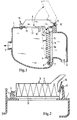
- FIG. 1 shows an air filter system with a housing 1, a Rohlufteinlass 2 and a clean air outlet 3.
- a filter element 4 is arranged, which is introduced into a cassette 5 and is fixed by an electronic control unit 6.
- a pivot axis 7 is present, which is accommodated on a pivoting contour 8.
- the pivoting contour 8 is attached to the housing 1.
- the cassette 5 On the side opposite the pivoting contour 8 side, the cassette 5 has a nose 5a.
- the housing 1 has a functional opening 11, through which the filter element 4 with the cassette 5 is introduced into the housing 1.
- the housing 1 has installations 18 which project into the interior of the housing 1.
- the systems 18 are arranged on both sides of the functional opening 11, wherein system nose 5 a of the cassette 5 in unstressed state, for. B. during transport of the pre-assembled filter element 4, abut the plants 18. In this case, the filter element 4 is not yet in the required position for filtration.
- the filter element 4 is enclosed by the frame of the cassette 5 and pressed with an edge 5b of the cassette 5 via a sealing bead 10 on a sealing surface 1a of the housing 1.
- the sealing bead 10 is arranged on the filter element 4 or the cassette 5.
- the sealing bead 10 can also be arranged on the housing 1.
- the electronic control unit 6 mounted in the functional opening 11 is received in a fastening axis 12 by claws 13 attached to the housing 1 and fixed to the housing 1 on the opposite side by means of a screw connection 14.
- a circumferential seal 15 is arranged, which ensures the seal between the housing 1 and the electronic control unit 6.
- FIG. 2 shows the filter element 4, which is fastened by a latching connection between the cassette 5 and the housing 1.
- a hook bracket 16 is arranged on the cassette 5, which corresponds to a latching element 17 of the housing 1.
- the hook bracket 16 and locking element 17 are flexurally elastic and form a detachable locking connection.
- the locking element 17 may also be formed by a, in the direction of hook bracket 16 projecting housing edge (not shown).
- the latching connection shown is suitable, for example, as a transport lock of the preassembled in the housing 1 filter element 4. The final sealing of the connection takes place by the pivoting of the control unit 6 according to FIG. 1 and thereby pressed against the housing 1 sealing bead 10th
Landscapes
- Chemical & Material Sciences (AREA)
- Chemical Kinetics & Catalysis (AREA)
- Engineering & Computer Science (AREA)
- Combustion & Propulsion (AREA)
- Mechanical Engineering (AREA)
- General Engineering & Computer Science (AREA)
- Filtering Of Dispersed Particles In Gases (AREA)
Description
- Die Erfindung betrifft eine Luftfilteranlage der im Oberbegriff des Patentanspruches 1 genannten Art. Außerdem betrifft die Erfindung ein Verfahren nach Anspruch 10 zum Einbringen eines Luftfilterelementes in eine Luftfilteranlage gemäß Anspruch 1.
- Da sich elektronische Steuergeräte im Betrieb aufheizen, wird der kontrollierte Luftstrom auf der Saugseite des Verbrennungsmotors zur Kühlung der elektronischen Steuergeräte genutzt. Dazu werden die elektronischen Steuergeräte derart am Luftfilter befestigt, dass eine wärmeübertragende Oberfläche direkt an den Luftstrom angrenzt.
- Es ist aus der
EP 0 997 632 eine Luftfilteranlage bekannt, welche aus zwei Kammern besteht. Eine Kammer zur Anbringung eines Filterelementes und eine Kammer zur Anbringung eines elektronischen Steuergerätes. Die beiden Kammern kommunizieren durch zwei Kanäle, die an der angrenzenden Wandung der Kammern eine Verbindung aufweisen. Zum Verschluss der Kammern sind eine Verschlußklappe für die Steuergerätekammer und ein Deckel für die Kammer des Filterelementes erforderlich, wobei am Deckel des Filterelementes ein Reinluftauslass angeordnet ist. Die Verschlußklappe verschließt die Kammer des elektronischen Steuergerätes und dient gleichzeitig zu dessen Fixierung. Zwischen Kammer und Verschlußklappe ist keine Dichtung angeordnet, somit strömt ein Teil der Rohluft über die Oberfläche des elektronischen Steuergerätes zum Filterelement. Die Außenluft wird durch den an der Filterkammer vorhandenen Rohlufteinlass angesaugt und strömt aufgrund der unterschiedlichen Druckverhältnisse, teilweise durch die Verbindungskanäle der Kammer des elektronischen Steuergerätes. Somit werden zwei Luftströmungen erzeugt, die das elektronische Steuergerät kühlen. - Nachteilig hierbei sind der hohe herstellungstechnische Aufwand und der Materialbedarf, welcher durch die Anordnung von zwei Gehäusekammern notwendig ist. Nachteilig ist auch die hohe Anzahl der notwendigen Einzelteile, da jedes Gehäuse einzeln verschlossen wird. Weiterhin ist das Steuergerät auf der Rohluftseite der Luftfilteranlage eingebaut, wodurch eine Verschmutzung zu erwarten ist.
- Die Aufgabe der Erfindung besteht darin, die oben genannten Nachteile zu vermeiden und mit geringem Materialaufwand und wenig Einzelteilen eine Luftfilteranlage zu bilden, die einfach und zuverlässig zu montieren ist und die Integration eines elektronischen Steuergerätes ermöglicht.
- Diese Aufgabe wird durch die Merkmale der Ansprüche 1 und 10 gelöst.
- Die erfindungsgemäße Luftfilteranlage für eine Brennkraftmaschine, insbesondere eines Fahrzeuges, verfügt über ein Gehäuse, in welchem über einen Rohlufteinlass Luft anströmt, einen Reinluftauslass, durch welchen die Luft ausströmt und ein dazwischen liegendes Filterelement, welches vom Luftstrom durchströmt wird. Das Gehäuse weist eine zusätzliche Funktionsöffnung und eine Kontur innerhalb des Gehäuses zur Aufnahme des Filterelementes auf. Die Funktionsöffnung bildet einen Zugang zur Innenseite des Gehäuses, wodurch das Filterelement ausgetauscht werden kann. Das Filterelement ist vorzugsweise ein Flachfilterelement und weist einen elastischen Dichtwulst auf. Der Dichtwulst korrespondiert mit einer innerhalb des Filtergehäuses angeordneten Dichtfläche und stellt eine dichte Verbindung zwischen einer Rohluft- und einer Reinluftseite her.
- Ein Funktionselement, welches insbesondere als elektronisches Steuergerät zur Steuerung eines Verbrennungsmotors ausgebildet ist, dient zum Verschluss der Funktionsöffnung. Das plattenförmig gestaltete elektronische Steuergerät verfügt über eine Seite, die außerhalb des Filtergehäuses liegt und an der die zur Funktion notwendigen Elektronikanschlüsse angebracht sind. Auf der innerhalb des Gehäuses liegenden Seite ist die Oberfläche derart gestaltet, dass eine optimierte Wärmeübertragung stattfindet. Dies wird z. B. durch die Anordnung von Kühlrippen, welche die Oberfläche vergrößern, erreicht. Das elektronische Steuergerät bildet somit den Deckel des Luftfiltergehäuses und grenzt an der inneren Seite am Luftstrom an, wodurch eine Kühlung des elektronischen Steuergerätes erreicht wird. Ist das elektronische Steuergerät demontiert, so ist durch die Funktionsöffnung der Zugang zum im Gehäuse liegenden Filterelement frei und das Filterelement kann ausgetauscht werden.
- Vorteilhaft ist, dass bei dieser Anordnung keine zusätzlichen Bauteile zum Verschließen des Luftfiltergehäuses und einer Steuergerätekammer erforderlich sind und dadurch auch weniger Teile montiert werden müssen. Weiterhin ist es möglich, das elektronische Steuergerät reinluftseitig anzuordnen und damit eine Verschmutzung der temperaturübertragenden Oberfläche zu vermeiden.
- Eine vorteilhafte Anordnung ergibt sich durch die Aufnahme des Filterelementes in einer Kassette. Die Kassette umschließt das mechanisch labile Filterelement an den Seitenflächen und stabilisiert den elastischen Dichtwulst. Dies kann dadurch erreicht werden, dass der Dichtwulst das Filterelements umfangsseitig überragt, wodurch eine Auflagefläche für die Kassette entsteht. Dadurch kann die Kassette den Dichtwulst definiert an eine Dichtfläche des Gehäuses andrücken. Somit bildet die Kassette eine Trägerfunktion des Filterelementes. Die Kassette kann innerhalb des Gehäuses mittels Schraub-, Rast-, oder Clipverbindungen befestigt werden oder durch Nocken, Federn oder Einführschrägen verspannt werden. Als Materialien kommen vorzugsweise Kunststoffe wie Polyamid oder Polypropylen in Frage, es können jedoch auch Metalle verwendet werden. Durch die Kassette wird das Filterelement stabilisiert und die dichtende Befestigung im Gehäuse gewährleistet. Da die Kassette im Wartungsfall nicht ausgetauscht werden muss, sondern nur das einfach gestaltete Filterelement ersetzt wird, ergeben sich günstigere Wartungskosten.
- Eine vorteilhafte Weiterbildung der Erfindung ist die Anordnung einer Kontur innerhalb des Luftfiltergehäuses, welche mit dem Filterelement korrespondiert. Die Kontur kann beispielsweise durch Nocken oder Stege gebildet werden, die einstückig mit dem Gehäuse hergestellt sind und an welchen sich die Kassette beim Einbringen oder in eingebautem Zustand abstützt. Die Kontur kann auch eine Vorbefestigung der Kassette dergestalt herstellen, dass die Kassette im Filtergehäuse fixiert, aber noch keine dichte Verbindung hergestellt ist. Die endgültige Befestigung kann zu einem späteren Zeitpunkt z. B. mit der Montage des Steuergerätes erfolgen. In Verbindung mit der beschriebenen korrespondierenden Kontur ergibt sich z. B. die Möglichkeit, die Kassette durch angebrachte Gleitelemente auf schräg oder gestuft zur Dichtfläche verlaufenden Schienen einzuführen und an die Dichtfläche anzuspannen. Hierdurch werden die Einbringung und die Verspannung des Elementes erleichtert.
- Eine weitere Ausgestaltung zur Befestigung der Kassette oder des Filterelementes ermöglicht die Anbringung einer Schwenkachse am Filterelement oder an der Kassette. Die Schwenkachse wird dabei in einer gegenüberliegenden Schwenkkontur aufgenommen. Die Schwenkachse kann beispielsweise durch einen zylinderförmigen Nocken und die Schwenkkontur durch einen klauenförmigen Absatz gebildet werden. Die Verbindung zwischen Schwenkachse und Schwenkkontur kann z. B. durch eine Verschnappung rastbar ausgeführt sein. Durch diese Anordnung wird die Einbringung der Kassette bzw. des Filterelementes vorteilhaft erleichtert und es findet eine Positionierung innerhalb des Gehäuses statt.
- Vorteilhaft ist die Befestigung des Filterelementes oder der Kassette im Gehäuse durch ein Befestigungselement. Dies kann eine Schraub-, Clip- oder eine rastende Verbindung sein. Beispielsweise kann durch einen gegenüber der Schwenkkontur angebrachten Haken, welcher im Gehäuse eine Aufnahme findet, das Filterelement durch Andrücken an die Dichtfläche fixiert werden. Die Fixierung kann endgültig sein oder zu einem späteren Zeitpunkt beispielsweise durch die Montage des Steuergerätes verstärkt werden. Durch die schwenkbare Befestigung kann aufgrund der Hebelwirkung ein hoher Druck auf die Dichtflächen ausgeübt werden, was zu einer zuverlässigen Dichtwirkung führt.
- Eine weitere vorteilhafte Ausgestaltung ist die Befestigung des elektronischen Steuergerätes am Gehäuse. Durch eine an einer Seite des elektronischen Steuergerätes angeordnete Befestigungsachse, welche am Gehäuse eine schwenkbare Aufnahme findet, wird das elektronische Steuergerät auf einer Seite eingebracht und kann auf der gegenüberliegenden Seite eingeschwenkt und mit Befestigungselementen fixiert werden. Auch hierbei ergibt sich eine vorteilhafte Abdichtung, da durch die Hebelwirkung ein hoher Druck auf die Dichtflächen zwischen elektronischem Steuergerät und dem Gehäuse aufgebracht wird. Weiterhin ist eine einfache wirtschaftliche Montage möglich.
- Gemäß einer weiteren vorteilhaften Gestaltung sind am elektronischen Steuergerät Druckkörper angebracht, welche in Form von Nocken, Stegen oder Klauen bei der Montage des elektronischen Steuergerätes einen Druck auf das Filterelement übertragen und somit die Abdichtung zwischen Filterelement und Gehäuse herstellen. Hierbei ist es vorteilhaft, am Filterelement oder der Kassette eine korrespondierende Kontur anzubringen, welche den Anpressdruck des elektronischen Steuergerätes aufnimmt und flächig auf die Dichtkontur des Filterelementes ableitet. Als Konturen sind dazu insbesondere Nocken geeignet, die am elektronischen Steuergerät oder am Filterelement bzw. der Kassette angebracht sein können.
- Die Druckkörper des elektronischen Steuergerätes und die korrespondierenden Konturen der Kassette können in ihrer Geometrie derart abgestimmt werden, dass sich bei Berücksichtigung aller möglichen Fertigungs- und Montagetoleranzen immer eine Überdeckung der Berührungspunkte ergibt. In Verbindung mit im Gehäuse angebrachten Anlagen kann der Schwenkbereich der Kassette eingegrenzt werden. Hierdurch wird gewährleistet, dass die Nocken des elektronischen Steuergerätes beim Einschwenken in das Gehäuse immer einen Anschlag in der Kassette finden. Da das Filterelement nur an der Dichtfläche anliegt, wenn es sich in übereinstimmender Position zum Gehäuse befindet, wird somit eine fehlerhafte Montage der Kassette ausgeschlossen. Zusätzlich wird durch die Anlagen das Einführen der Kassette in das Gehäuse erleichtert.
- Dies ermöglicht eine sehr einfache und günstige Montage des elektronischen Steuergerätes, wodurch die beiden Dichtflächen zwischen Filterelement und Luftfiltergehäuse sowie zwischen elektronischem Steuergerät und Luftfiltergehäuse durch einen Montageablauf hergestellt werden.
- Eine vorteilhafte Abdichtung zwischen elektronischem Steuergerät und Luftfiltergehäuse ist die Anordnung einer umlaufenden Dichtung in einer Nut, die die Funktionsöffnung des elektronischen Steuergerätes umschließt. Hierdurch kann die Dichtung bereits vormontiert mit der Luftfilteranlage ausgeliefert werden und erleichtert zusätzlich die Montage des elektronischen Steuergerätes.
- Vorteilhaft ist die Anordnung des elektronischen Steuergerätes an einer der Luftströmung zugewandten Seite. Diese Anordnung wird mit der Abstimmung der Luftführungsgeometrie bestimmt und ermöglicht einen optimalen Wärmeaustausch zwischen elektronischem Steuergerät und Luftstrom.
- Das erfindungsgemäße Verfahren zum Einbringen eines Filterelementes in die Innenseite eines Luftfiltergehäuses durch eine Funktionsöffnung kennzeichnet sich dadurch, dass die Funktionsöffnung gleichzeitig die Aufnahme eines elektronischen Steuergerätes ermöglicht, welches durch den im Luftfiltergehäuse anliegenden Luftstrom gekühlt wird.
- Das Filterelement wird durch die Funktionsöffnung mit der Seite, auf welcher sich eine angebrachte Schwenkachse befindet, ins Luftfiltergehäuse eingebracht. Die Schwenkachse findet im Filtergehäuse eine Aufnahme. Das Filterelement wird an die Dichtfläche angedrückt und über eine Rastung fixiert. Anschließend wird das elektronische Steuergerät mit der Seite, an welcher sich die schwenkbare Befestigungsachse befindet, in die dazu korrespondierende Aufnahmekontur der Befestigungsachse eingeschoben. Das elektronische Steuergerät wird jetzt zum Gehäuse hin geschwenkt und mit den vorgesehenen Befestigungselementen fixiert. Durch das Einschwenken des elektronischen Steuergerätes wird das Filterelement über Spannocken an die Dichtfläche zum Luftfiltergehäuse angedrückt. Gleichzeitig wird das elektronische Steuergerät an die außenliegende Dichtfläche zum Gehäuse angedrückt. Vorteilhaft werden in einem Arbeitsgang sowohl das elektronisches Steuergerät als auch das Filterelement mit der jeweiligen Dichtfläche verspannt. Weiterhin braucht kein zusätzliches Verschlußteil an das Luftfiltergehäuse angebracht werden.
- Ein vorteilhafter Effekt des Verfahrens wird dadurch erzielt, dass das im Luftfiltergehäuse montierte Filterelement durch ein Befestigungselement fixiert wird. Dazu bietet sich die Anbringung eines Hakens an der Kassette an, der sich beim Andrücken in einer am Gehäuse vorgesehenen Kante einhakt, wodurch das Filterelement an die vorgesehene Dichtkontur am Gehäuse angedrückt wird. Hierdurch wird das Filterelement in seiner Lage fixiert und kann zu weiteren Montageorten transportiert werden. Insbesondere wird es ermöglicht, die vormontierte Luftfilteranlage dem Kunden auszuliefern, welcher zur Komplettierung nur noch das jeweilige elektronische Steuergerät zu montieren braucht.
- Diese und weitere Merkmale von bevorzugten Weiterbildungen der Erfindung gehen außer aus den Ansprüchen auch aus der Beschreibung und der Zeichnung hervor, wobei die einzelnen Merkmale jeweils für sich allein oder zu mehreren in Form von Unterkombinationen bei der Ausführungsform der Erfindung und auf anderen Gebieten verwirklicht sein und vorteilhafte sowie für sich schutzfähige Ausführungen darstellen können, für die hier Schutz beansprucht wird.
- Weitere Einzelheiten der Erfindung werden in der Zeichnung anhand von schematischen Ausführungsbeispielen beschrieben. Hierbei zeigen
- Figur 1
- eine Luftfilteranlage im Vollschnitt und
- Figur 2
- ein Filterelement in einer Teilansicht.
-
Figur 1 zeigt eine Luftfilteranlage mit einem Gehäuse 1, einem Rohlufteinlass 2 und einem Reinluftauslass 3. In dem Gehäuse 1 ist ein Filterelement 4 angeordnet, welches in eine Kassette 5 eingebracht ist und durch ein elektronisches Steuergerät 6 fixiert ist. - An der Kassette 5 ist eine Schwenkachse 7 vorhanden, welche an einer Schwenkkontur 8 aufgenommen ist. Die Schwenkkontur 8 ist am Gehäuse 1 angebracht. Auf der der Schwenkkontur 8 gegenüber liegenden Seite verfügt die Kassette 5 über eine Nase 5a.
- Durch einen Spannocken 9, welcher am elektronischen Steuergerät 6 angebracht ist und mit der Nase 5a korrespondiert, ist die Kassette 5 fixiert. Das Gehäuse 1 verfügt über eine Funktionsöffnung 11, durch welche das Filterelement 4 mit der Kassette 5 in das Gehäuse 1 eingebracht wird. Im Randbereich der Funktionsöffnung 11 verfügt das Gehäuse 1 über Anlagen 18, welche in das Innere des Gehäuses 1 hineinragen. Die Anlagen 18 sind beidseitig der Funktionsöffnung 11 angeordnet, wobei Anlagenasen 5a der Kassette 5 in unverspanntem Zustand, z. B. beim Transport des vormontierten Filterelementes 4, an den Anlagen 18 anliegen. Hierbei befindet sich das Filterelement 4 noch nicht in der zur Filtration erforderlichen Lage. Das Filterelement 4 wird vom Rahmen der Kassette 5 umschlossen und mit einer Kante 5b der Kassette 5 über einen Dichtwulst 10 auf eine Dichtfläche 1a des Gehäuses 1 angedrückt. Hierbei ist der Dichtwulst 10 an dem Filterelement 4 bzw. der Kassette 5 angeordnet. Bei alternativen Ausgestaltungen kann der Dichtwulst 10 auch am Gehäuse 1 angeordnet sein. Das in die Funktionsöffnung 11 montierte elektronische Steuergerät 6 ist in einer Befestigungsachse 12 durch am Gehäuse 1 angebrachte Klauen 13 aufgenommen und auf der gegenüberliegenden Seite mittels einer Schraubverbindung 14 an dem Gehäuse 1 fixiert. Zwischen dem Gehäuse 1 und dem Steuergerät 6 ist eine umlaufende Dichtung 15 angeordnet, welche die Abdichtung zwischen Gehäuse 1 und elektronischem Steuergerät 6 gewährleistet. Beim Einschwenken des elektronischen Steuergerätes 6 wird die Kassette 5 und somit das Filterelement 4 durch Spannocken 9, welche am Steuergerät 6 angeordnet sind, gegen den Dichtwulst 10 gepresst und somit in dem Gehäuse 1 dichtend fixiert.
-
Figur 2 zeigt das Filterelement 4, welches durch eine Rastverbindung zwischen Kassette 5 und Gehäuse 1 befestigt ist. DerFigur 1 entsprechende Bauteile sind mit gleichen Bezugszeichen versehen. Gegenüber der zwischen Schwenkachse 7 und Schwenkkontur 8 gebildeten Schwenkverbindung ist an der Kassette 5 ist ein Hakenbügel 16 angeordnet, welcher mit einem Rastelement 17 des Gehäuses 1 korrespondiert. Hakenbügel 16 und Rastelement 17 sind biegeelastisch und bilden eine lösbare Rastverbindung. Bei anderen Ausgestaltungen kann das Rastelement 17 auch durch eine, in Richtung Hakenbügel 16 ragende Gehäusekante gebildet werden (nicht dargestellt). Die gezeigte Rastverbindung eignet sich beispielsweise als Transportsicherung des im Gehäuse 1 vormontierten Filterelementes 4. Die endgültige Abdichtung der Verbindung erfolgt durch das Einschwenken des Steuergerätes 6 gemäßFigur 1 und den dadurch an das Gehäuse 1 angepressten Dichtwulst 10.
Claims (10)
- Luftfilteranlage für eine Brennkraftmaschine, aufweisend ein Gehäuse, einen Rohlufteinlass, einen Reinluftauslass, ein dichtend zwischen Rohlufteinlass und Reinluftauslass angeordnetes Filterelement und eine zusätzliche Funktionsöffnung im Gehäuse, wobei das Filterelement durch die Funktionsöffnung in das Gehäuse einbringbar ist, dadurch gekennzeichnet, dass die Funktionsöffnung des Gehäuses durch ein Funktionselement verschließbar ist, wobei das Funktionselement ein elektronisches Ste u-ergerät ist.
- Luftfilteranlage nach Anspruch 1, dadurch gekennzeichnet, dass das Filterelement in einer Kassette angeordnet ist, welche durch die Funktionsöffnung in das Gehäuse einbringbar ist.
- Luftfilteranlage nach einem der vorhergehenden Ansprüche, dadurch gekennzeichnet, dass das Gehäuse eine Kontur aufweist, durch welche das Filterelement positioniert wird.
- Luftfilteranlage nach einem der vorhergehenden Ansprüche, dadurch gekennzeichnet, dass das Filterelement oder die Kassette auf einer Seite schwenkbar montiert ist.
- Luftfilteranlage nach einem der vorhergehenden Ansprüche, dadurch gekennzeichnet, dass das Filterelement oder die Kassette im Gehäuse durch wenigstens ein Befestigungselement lösbar mit dem Gehäuse verbunden ist.
- Luftfilteranlage nach einem der vorhergehenden Ansprüche, dadurch gekennzeichnet, dass das Funktionselement auf einer Seite schwenkbar montiert ist und auf der gegenüberliegenden Seite lösbar mit dem Gehäuse verbunden ist.
- Luftfilteranlage nach einem der vorhergehenden Ansprüche, dadurch gekennzeichnet, dass am Funktionselement und / oder an der Kassette bzw. dem Filterelement Druckkörper angebracht sind, die beim Befestigen des Funktionselementes einen Anpressdruck auf das Filterelement ausüben, wodurch eine Verpressung zwischen Gehäuse und Filterelement hergestellt ist.
- Luftfilteranlage nach einem der vorhergehenden Ansprüche, dadurch gekennzeichnet dass zwischen Gehäuse und Funktionselement eine umlaufende Dichtung angeordnet ist.
- Luftfilteranlage nach einem der vorhergehenden Ansprüche, dadurch gekennzeichnet, dass das elektronische Steuergerät an der Innenseite des Gehäuses an einer der Luftströmung zugewandten Seite angeordnet ist.
- Verfahren zur Wartung einer Luftfilteranlage gemäß Anspruch 1 bis 9, aufweisend zumindest folgende Arbeitsschritte:- Öffnen der Funktionsöffnung durch Entfernen des Funktionselementes,- Entfernen des Filterelementes aus dem Gehäuse durch die Funktionsöffnung,- Einbringen des neuen Filterelementes durch die Funktionsöffnung,- Verschließen der Funktionsöffnung durch das Funktionselement.
Applications Claiming Priority (2)
| Application Number | Priority Date | Filing Date | Title |
|---|---|---|---|
| DE10345684 | 2003-10-01 | ||
| DE10345684A DE10345684A1 (de) | 2003-10-01 | 2003-10-01 | Luftfilteranlage im Ansaugtrakt einer Brennkraftmaschine |
Publications (3)
| Publication Number | Publication Date |
|---|---|
| EP1520975A2 EP1520975A2 (de) | 2005-04-06 |
| EP1520975A3 EP1520975A3 (de) | 2010-03-10 |
| EP1520975B1 true EP1520975B1 (de) | 2011-11-02 |
Family
ID=34306180
Family Applications (1)
| Application Number | Title | Priority Date | Filing Date |
|---|---|---|---|
| EP04104750A Expired - Lifetime EP1520975B1 (de) | 2003-10-01 | 2004-09-29 | Luftfilteranlage im Ansaugtrakt einer Brennkraftmaschine |
Country Status (4)
| Country | Link |
|---|---|
| EP (1) | EP1520975B1 (de) |
| AT (1) | ATE531925T1 (de) |
| DE (1) | DE10345684A1 (de) |
| ES (1) | ES2376384T3 (de) |
Families Citing this family (5)
| Publication number | Priority date | Publication date | Assignee | Title |
|---|---|---|---|---|
| DE102005031501B4 (de) | 2005-07-06 | 2021-12-09 | Andreas Stihl Ag & Co. Kg | Luftfilter |
| DE202008011714U1 (de) | 2008-09-03 | 2010-01-28 | Mann+Hummel Gmbh | Luftfiltersystem für eine Brennkraftmaschine |
| DE102014015760B4 (de) * | 2014-10-27 | 2016-07-14 | Mann + Hummel Gmbh | Filtergehäuse mit Hebelelement |
| US20200072169A1 (en) | 2018-08-28 | 2020-03-05 | Parker-Hannifin Corporation | Non-cylindrical filter element and side entry air cleaner incorporating the same |
| US20220274041A1 (en) | 2021-02-26 | 2022-09-01 | Parker-Hannifin Corporation | Side entry wave seal air cleaner |
Family Cites Families (8)
| Publication number | Priority date | Publication date | Assignee | Title |
|---|---|---|---|---|
| CA1043899A (en) * | 1975-05-30 | 1978-12-05 | Ivor W. Carter | Arrangement for mounting electronic circuit boards on an engine air filter housing |
| DE3338653A1 (de) * | 1983-10-25 | 1985-05-02 | Volkswagenwerk Ag, 3180 Wolfsburg | Luftfilter fuer eine brennkraftmaschine |
| JPH04203437A (ja) * | 1990-11-30 | 1992-07-24 | Hitachi Ltd | 自動車用制御機器 |
| JP3473642B2 (ja) * | 1994-09-20 | 2003-12-08 | 株式会社デンソー | 燃料噴射装置 |
| JPH08210201A (ja) * | 1995-02-06 | 1996-08-20 | Kansei Corp | 電装部品内蔵のエアクリーナボックス |
| DE19534036A1 (de) * | 1995-09-14 | 1997-03-20 | Mann & Hummel Filter | Luftfilter |
| GB9823556D0 (en) * | 1998-10-28 | 1998-12-23 | Rover Group | A motor vehicle |
| JP2002188535A (ja) * | 2000-12-18 | 2002-07-05 | Auto Network Gijutsu Kenkyusho:Kk | エアクリーナ装置 |
-
2003
- 2003-10-01 DE DE10345684A patent/DE10345684A1/de not_active Withdrawn
-
2004
- 2004-09-29 ES ES04104750T patent/ES2376384T3/es not_active Expired - Lifetime
- 2004-09-29 AT AT04104750T patent/ATE531925T1/de active
- 2004-09-29 EP EP04104750A patent/EP1520975B1/de not_active Expired - Lifetime
Also Published As
| Publication number | Publication date |
|---|---|
| ATE531925T1 (de) | 2011-11-15 |
| ES2376384T3 (es) | 2012-03-13 |
| EP1520975A2 (de) | 2005-04-06 |
| EP1520975A3 (de) | 2010-03-10 |
| DE10345684A1 (de) | 2005-04-21 |
Similar Documents
| Publication | Publication Date | Title |
|---|---|---|
| DE102014006852B4 (de) | Hohlfilterelement, Filtergehäuse und Filter | |
| EP3228376B1 (de) | Filtermodul mit einem filterelement und einem befestigungsrahmen und luftfilteranlage mit einem filtermodul | |
| EP1818533A2 (de) | Sicherungssytem für eine Kohlenwasserstofffalle | |
| EP2582444B1 (de) | Filtereinsatz | |
| WO2012110605A1 (de) | Luftfilterelement, luftfiltergehäuse und luftfiltersystem | |
| WO2008017475A1 (de) | Druckluftversorgungseinrichtung | |
| DE102013003753A1 (de) | Filter, Filterelement und Filtergehäuse | |
| DE19638790A1 (de) | Luftfilter | |
| DE102008036913B3 (de) | Luftfiltersystem | |
| WO2011069864A1 (de) | Filterelement und luftfilter | |
| DE2816526A1 (de) | Oelfilter, insbesondere fuer dieseloel, und verfahren zu seiner herstellung | |
| WO2016146250A1 (de) | Filtereinrichtung und filterelement, insbesondere für einen kraftwagen | |
| DE102016004575A1 (de) | Haube eines Multi-Zyklonblocks eines Luftreinigers und Luftreiniger | |
| EP3098405A1 (de) | Abgasbehandlungseinrichtung mit austauschbarem einsatz | |
| EP1520975B1 (de) | Luftfilteranlage im Ansaugtrakt einer Brennkraftmaschine | |
| EP2888023B1 (de) | Filtereinrichtung, insbesondere zur gasfiltration | |
| EP3390185A1 (de) | Lufttrocknerpatrone | |
| EP2305992A2 (de) | Luftfilter für eine Brennkraftmaschine | |
| EP1870570A2 (de) | Einrichtung mit einem Wärmetauscher und einem Flüssigkeitsfilter | |
| EP4139023A1 (de) | Filterelement für eine luftfiltereinrichtung eines kraftwagens und luftfiltereinrichtung | |
| DE102005040607A1 (de) | Anordnung zur Befestigung eines Wärmeübertragers an einem anderen | |
| EP4017770A1 (de) | Rückschlagventil-vorrichtung | |
| DE29705649U1 (de) | Deckel für ein Filtergehäuse | |
| DE3924676C2 (de) | ||
| DE102009018752A1 (de) | Schwenkbare Reinlufthaube |
Legal Events
| Date | Code | Title | Description |
|---|---|---|---|
| PUAI | Public reference made under article 153(3) epc to a published international application that has entered the european phase |
Free format text: ORIGINAL CODE: 0009012 |
|
| AK | Designated contracting states |
Kind code of ref document: A2 Designated state(s): AT BE BG CH CY CZ DE DK EE ES FI FR GB GR HU IE IT LI LU MC NL PL PT RO SE SI SK TR |
|
| AX | Request for extension of the european patent |
Extension state: AL HR LT LV MK |
|
| PUAL | Search report despatched |
Free format text: ORIGINAL CODE: 0009013 |
|
| AK | Designated contracting states |
Kind code of ref document: A3 Designated state(s): AT BE BG CH CY CZ DE DK EE ES FI FR GB GR HU IE IT LI LU MC NL PL PT RO SE SI SK TR |
|
| AX | Request for extension of the european patent |
Extension state: AL HR LT LV MK |
|
| 17P | Request for examination filed |
Effective date: 20100414 |
|
| AKX | Designation fees paid |
Designated state(s): AT BE BG CH CY CZ DE DK EE ES FI FR GB GR HU IE IT LI LU MC NL PL PT RO SE SI SK TR |
|
| RIC1 | Information provided on ipc code assigned before grant |
Ipc: F02M 35/024 20060101AFI20110315BHEP |
|
| GRAP | Despatch of communication of intention to grant a patent |
Free format text: ORIGINAL CODE: EPIDOSNIGR1 |
|
| GRAS | Grant fee paid |
Free format text: ORIGINAL CODE: EPIDOSNIGR3 |
|
| GRAA | (expected) grant |
Free format text: ORIGINAL CODE: 0009210 |
|
| AK | Designated contracting states |
Kind code of ref document: B1 Designated state(s): AT BE BG CH CY CZ DE DK EE ES FI FR GB GR HU IE IT LI LU MC NL PL PT RO SE SI SK TR |
|
| REG | Reference to a national code |
Ref country code: GB Ref legal event code: FG4D Free format text: NOT ENGLISH |
|
| REG | Reference to a national code |
Ref country code: CH Ref legal event code: EP |
|
| REG | Reference to a national code |
Ref country code: IE Ref legal event code: FG4D |
|
| REG | Reference to a national code |
Ref country code: DE Ref legal event code: R096 Ref document number: 502004013024 Country of ref document: DE Effective date: 20120112 |
|
| REG | Reference to a national code |
Ref country code: NL Ref legal event code: VDEP Effective date: 20111102 |
|
| REG | Reference to a national code |
Ref country code: ES Ref legal event code: FG2A Ref document number: 2376384 Country of ref document: ES Kind code of ref document: T3 Effective date: 20120313 |
|
| PG25 | Lapsed in a contracting state [announced via postgrant information from national office to epo] |
Ref country code: SE Free format text: LAPSE BECAUSE OF FAILURE TO SUBMIT A TRANSLATION OF THE DESCRIPTION OR TO PAY THE FEE WITHIN THE PRESCRIBED TIME-LIMIT Effective date: 20111102 Ref country code: NL Free format text: LAPSE BECAUSE OF FAILURE TO SUBMIT A TRANSLATION OF THE DESCRIPTION OR TO PAY THE FEE WITHIN THE PRESCRIBED TIME-LIMIT Effective date: 20111102 Ref country code: GR Free format text: LAPSE BECAUSE OF FAILURE TO SUBMIT A TRANSLATION OF THE DESCRIPTION OR TO PAY THE FEE WITHIN THE PRESCRIBED TIME-LIMIT Effective date: 20120203 Ref country code: PL Free format text: LAPSE BECAUSE OF FAILURE TO SUBMIT A TRANSLATION OF THE DESCRIPTION OR TO PAY THE FEE WITHIN THE PRESCRIBED TIME-LIMIT Effective date: 20111102 Ref country code: SI Free format text: LAPSE BECAUSE OF FAILURE TO SUBMIT A TRANSLATION OF THE DESCRIPTION OR TO PAY THE FEE WITHIN THE PRESCRIBED TIME-LIMIT Effective date: 20111102 Ref country code: PT Free format text: LAPSE BECAUSE OF FAILURE TO SUBMIT A TRANSLATION OF THE DESCRIPTION OR TO PAY THE FEE WITHIN THE PRESCRIBED TIME-LIMIT Effective date: 20120302 |
|
| REG | Reference to a national code |
Ref country code: IE Ref legal event code: FD4D |
|
| PG25 | Lapsed in a contracting state [announced via postgrant information from national office to epo] |
Ref country code: CY Free format text: LAPSE BECAUSE OF FAILURE TO SUBMIT A TRANSLATION OF THE DESCRIPTION OR TO PAY THE FEE WITHIN THE PRESCRIBED TIME-LIMIT Effective date: 20111102 |
|
| PG25 | Lapsed in a contracting state [announced via postgrant information from national office to epo] |
Ref country code: BG Free format text: LAPSE BECAUSE OF FAILURE TO SUBMIT A TRANSLATION OF THE DESCRIPTION OR TO PAY THE FEE WITHIN THE PRESCRIBED TIME-LIMIT Effective date: 20120202 Ref country code: EE Free format text: LAPSE BECAUSE OF FAILURE TO SUBMIT A TRANSLATION OF THE DESCRIPTION OR TO PAY THE FEE WITHIN THE PRESCRIBED TIME-LIMIT Effective date: 20111102 Ref country code: CZ Free format text: LAPSE BECAUSE OF FAILURE TO SUBMIT A TRANSLATION OF THE DESCRIPTION OR TO PAY THE FEE WITHIN THE PRESCRIBED TIME-LIMIT Effective date: 20111102 Ref country code: SK Free format text: LAPSE BECAUSE OF FAILURE TO SUBMIT A TRANSLATION OF THE DESCRIPTION OR TO PAY THE FEE WITHIN THE PRESCRIBED TIME-LIMIT Effective date: 20111102 Ref country code: DK Free format text: LAPSE BECAUSE OF FAILURE TO SUBMIT A TRANSLATION OF THE DESCRIPTION OR TO PAY THE FEE WITHIN THE PRESCRIBED TIME-LIMIT Effective date: 20111102 Ref country code: IE Free format text: LAPSE BECAUSE OF FAILURE TO SUBMIT A TRANSLATION OF THE DESCRIPTION OR TO PAY THE FEE WITHIN THE PRESCRIBED TIME-LIMIT Effective date: 20111102 |
|
| PG25 | Lapsed in a contracting state [announced via postgrant information from national office to epo] |
Ref country code: RO Free format text: LAPSE BECAUSE OF FAILURE TO SUBMIT A TRANSLATION OF THE DESCRIPTION OR TO PAY THE FEE WITHIN THE PRESCRIBED TIME-LIMIT Effective date: 20111102 |
|
| PLBE | No opposition filed within time limit |
Free format text: ORIGINAL CODE: 0009261 |
|
| STAA | Information on the status of an ep patent application or granted ep patent |
Free format text: STATUS: NO OPPOSITION FILED WITHIN TIME LIMIT |
|
| 26N | No opposition filed |
Effective date: 20120803 |
|
| REG | Reference to a national code |
Ref country code: DE Ref legal event code: R097 Ref document number: 502004013024 Country of ref document: DE Effective date: 20120803 |
|
| BERE | Be: lapsed |
Owner name: MANN + HUMMEL G.M.B.H. Effective date: 20120930 |
|
| PG25 | Lapsed in a contracting state [announced via postgrant information from national office to epo] |
Ref country code: MC Free format text: LAPSE BECAUSE OF NON-PAYMENT OF DUE FEES Effective date: 20120930 |
|
| REG | Reference to a national code |
Ref country code: CH Ref legal event code: PL |
|
| PG25 | Lapsed in a contracting state [announced via postgrant information from national office to epo] |
Ref country code: FI Free format text: LAPSE BECAUSE OF FAILURE TO SUBMIT A TRANSLATION OF THE DESCRIPTION OR TO PAY THE FEE WITHIN THE PRESCRIBED TIME-LIMIT Effective date: 20111102 |
|
| PG25 | Lapsed in a contracting state [announced via postgrant information from national office to epo] |
Ref country code: CH Free format text: LAPSE BECAUSE OF NON-PAYMENT OF DUE FEES Effective date: 20120930 Ref country code: BE Free format text: LAPSE BECAUSE OF NON-PAYMENT OF DUE FEES Effective date: 20120930 Ref country code: LI Free format text: LAPSE BECAUSE OF NON-PAYMENT OF DUE FEES Effective date: 20120930 |
|
| REG | Reference to a national code |
Ref country code: AT Ref legal event code: MM01 Ref document number: 531925 Country of ref document: AT Kind code of ref document: T Effective date: 20120929 |
|
| PG25 | Lapsed in a contracting state [announced via postgrant information from national office to epo] |
Ref country code: AT Free format text: LAPSE BECAUSE OF NON-PAYMENT OF DUE FEES Effective date: 20120929 |
|
| PG25 | Lapsed in a contracting state [announced via postgrant information from national office to epo] |
Ref country code: TR Free format text: LAPSE BECAUSE OF FAILURE TO SUBMIT A TRANSLATION OF THE DESCRIPTION OR TO PAY THE FEE WITHIN THE PRESCRIBED TIME-LIMIT Effective date: 20111102 |
|
| PG25 | Lapsed in a contracting state [announced via postgrant information from national office to epo] |
Ref country code: LU Free format text: LAPSE BECAUSE OF NON-PAYMENT OF DUE FEES Effective date: 20120929 |
|
| PG25 | Lapsed in a contracting state [announced via postgrant information from national office to epo] |
Ref country code: HU Free format text: LAPSE BECAUSE OF FAILURE TO SUBMIT A TRANSLATION OF THE DESCRIPTION OR TO PAY THE FEE WITHIN THE PRESCRIBED TIME-LIMIT Effective date: 20040929 |
|
| REG | Reference to a national code |
Ref country code: FR Ref legal event code: PLFP Year of fee payment: 12 |
|
| PGFP | Annual fee paid to national office [announced via postgrant information from national office to epo] |
Ref country code: DE Payment date: 20150922 Year of fee payment: 12 Ref country code: GB Payment date: 20150917 Year of fee payment: 12 Ref country code: ES Payment date: 20150928 Year of fee payment: 12 |
|
| PGFP | Annual fee paid to national office [announced via postgrant information from national office to epo] |
Ref country code: FR Payment date: 20150922 Year of fee payment: 12 |
|
| PGFP | Annual fee paid to national office [announced via postgrant information from national office to epo] |
Ref country code: IT Payment date: 20150924 Year of fee payment: 12 |
|
| REG | Reference to a national code |
Ref country code: DE Ref legal event code: R119 Ref document number: 502004013024 Country of ref document: DE |
|
| GBPC | Gb: european patent ceased through non-payment of renewal fee |
Effective date: 20160929 |
|
| REG | Reference to a national code |
Ref country code: FR Ref legal event code: ST Effective date: 20170531 |
|
| PG25 | Lapsed in a contracting state [announced via postgrant information from national office to epo] |
Ref country code: FR Free format text: LAPSE BECAUSE OF NON-PAYMENT OF DUE FEES Effective date: 20160930 Ref country code: DE Free format text: LAPSE BECAUSE OF NON-PAYMENT OF DUE FEES Effective date: 20170401 Ref country code: GB Free format text: LAPSE BECAUSE OF NON-PAYMENT OF DUE FEES Effective date: 20160929 |
|
| PG25 | Lapsed in a contracting state [announced via postgrant information from national office to epo] |
Ref country code: IT Free format text: LAPSE BECAUSE OF NON-PAYMENT OF DUE FEES Effective date: 20160929 |
|
| PG25 | Lapsed in a contracting state [announced via postgrant information from national office to epo] |
Ref country code: ES Free format text: LAPSE BECAUSE OF NON-PAYMENT OF DUE FEES Effective date: 20160930 |
|
| REG | Reference to a national code |
Ref country code: ES Ref legal event code: FD2A Effective date: 20181126 |