EP1520845A1 - Vorrichtung und Verfahren zur Kompostierung - Google Patents
Vorrichtung und Verfahren zur Kompostierung Download PDFInfo
- Publication number
- EP1520845A1 EP1520845A1 EP04022142A EP04022142A EP1520845A1 EP 1520845 A1 EP1520845 A1 EP 1520845A1 EP 04022142 A EP04022142 A EP 04022142A EP 04022142 A EP04022142 A EP 04022142A EP 1520845 A1 EP1520845 A1 EP 1520845A1
- Authority
- EP
- European Patent Office
- Prior art keywords
- composting chamber
- composting
- chamber
- grinder
- mixer
- Prior art date
- Legal status (The legal status is an assumption and is not a legal conclusion. Google has not performed a legal analysis and makes no representation as to the accuracy of the status listed.)
- Granted
Links
- 238000009264 composting Methods 0.000 title claims abstract description 130
- 238000000034 method Methods 0.000 title claims abstract description 29
- 238000000227 grinding Methods 0.000 claims abstract description 55
- 239000000463 material Substances 0.000 claims abstract description 35
- 238000002156 mixing Methods 0.000 claims abstract description 13
- 230000009471 action Effects 0.000 claims abstract description 10
- 238000010008 shearing Methods 0.000 claims abstract description 7
- 230000002093 peripheral effect Effects 0.000 claims description 13
- 238000010408 sweeping Methods 0.000 claims description 6
- 238000004891 communication Methods 0.000 claims description 5
- 238000007789 sealing Methods 0.000 claims description 4
- 239000011810 insulating material Substances 0.000 claims description 3
- 238000011068 loading method Methods 0.000 claims description 3
- 238000000354 decomposition reaction Methods 0.000 abstract description 14
- 230000008569 process Effects 0.000 abstract description 14
- 239000002361 compost Substances 0.000 abstract description 11
- 230000000737 periodic effect Effects 0.000 abstract description 3
- 238000009413 insulation Methods 0.000 description 10
- 238000010438 heat treatment Methods 0.000 description 7
- 230000004913 activation Effects 0.000 description 6
- 239000010868 animal carcass Substances 0.000 description 6
- 244000005700 microbiome Species 0.000 description 6
- QVGXLLKOCUKJST-UHFFFAOYSA-N atomic oxygen Chemical compound [O] QVGXLLKOCUKJST-UHFFFAOYSA-N 0.000 description 5
- 229910052760 oxygen Inorganic materials 0.000 description 5
- 239000001301 oxygen Substances 0.000 description 5
- 239000003566 sealing material Substances 0.000 description 5
- XLYOFNOQVPJJNP-UHFFFAOYSA-N water Substances O XLYOFNOQVPJJNP-UHFFFAOYSA-N 0.000 description 5
- 239000000203 mixture Substances 0.000 description 4
- 238000010276 construction Methods 0.000 description 3
- 210000000988 bone and bone Anatomy 0.000 description 2
- 239000005416 organic matter Substances 0.000 description 2
- 239000002245 particle Substances 0.000 description 2
- 238000003756 stirring Methods 0.000 description 2
- 229920003043 Cellulose fiber Polymers 0.000 description 1
- 239000011248 coating agent Substances 0.000 description 1
- 238000000576 coating method Methods 0.000 description 1
- 238000001816 cooling Methods 0.000 description 1
- 230000008878 coupling Effects 0.000 description 1
- 238000010168 coupling process Methods 0.000 description 1
- 238000005859 coupling reaction Methods 0.000 description 1
- 238000001514 detection method Methods 0.000 description 1
- 238000001035 drying Methods 0.000 description 1
- 238000012544 monitoring process Methods 0.000 description 1
- 239000011368 organic material Substances 0.000 description 1
- 238000002360 preparation method Methods 0.000 description 1
- 238000005086 pumping Methods 0.000 description 1
- 230000004044 response Effects 0.000 description 1
- 239000002881 soil fertilizer Substances 0.000 description 1
- 239000007787 solid Substances 0.000 description 1
- 239000010902 straw Substances 0.000 description 1
- 235000013311 vegetables Nutrition 0.000 description 1
Images


Classifications
-
- C—CHEMISTRY; METALLURGY
- C05—FERTILISERS; MANUFACTURE THEREOF
- C05F—ORGANIC FERTILISERS NOT COVERED BY SUBCLASSES C05B, C05C, e.g. FERTILISERS FROM WASTE OR REFUSE
- C05F17/00—Preparation of fertilisers characterised by biological or biochemical treatment steps, e.g. composting or fermentation
- C05F17/90—Apparatus therefor
- C05F17/907—Small-scale devices without mechanical means for feeding or discharging material, e.g. garden compost bins
-
- Y—GENERAL TAGGING OF NEW TECHNOLOGICAL DEVELOPMENTS; GENERAL TAGGING OF CROSS-SECTIONAL TECHNOLOGIES SPANNING OVER SEVERAL SECTIONS OF THE IPC; TECHNICAL SUBJECTS COVERED BY FORMER USPC CROSS-REFERENCE ART COLLECTIONS [XRACs] AND DIGESTS
- Y02—TECHNOLOGIES OR APPLICATIONS FOR MITIGATION OR ADAPTATION AGAINST CLIMATE CHANGE
- Y02P—CLIMATE CHANGE MITIGATION TECHNOLOGIES IN THE PRODUCTION OR PROCESSING OF GOODS
- Y02P20/00—Technologies relating to chemical industry
- Y02P20/141—Feedstock
- Y02P20/145—Feedstock the feedstock being materials of biological origin
-
- Y—GENERAL TAGGING OF NEW TECHNOLOGICAL DEVELOPMENTS; GENERAL TAGGING OF CROSS-SECTIONAL TECHNOLOGIES SPANNING OVER SEVERAL SECTIONS OF THE IPC; TECHNICAL SUBJECTS COVERED BY FORMER USPC CROSS-REFERENCE ART COLLECTIONS [XRACs] AND DIGESTS
- Y02—TECHNOLOGIES OR APPLICATIONS FOR MITIGATION OR ADAPTATION AGAINST CLIMATE CHANGE
- Y02W—CLIMATE CHANGE MITIGATION TECHNOLOGIES RELATED TO WASTEWATER TREATMENT OR WASTE MANAGEMENT
- Y02W30/00—Technologies for solid waste management
- Y02W30/40—Bio-organic fraction processing; Production of fertilisers from the organic fraction of waste or refuse
Definitions
- the present invention relates to a composting device and method of use thereof for producing compost material.
- US patent 3,845,939 to Waldenville describes a composting apparatus including mixing elements to periodically mix the matter to be composted as in some of the previous prior art.
- a shredder device is provided at the inlet of the compost device to break up matter to be composted into smaller pieces however the particular construction of the shredding elements located in a narrow inlet tube would not permit large items like animal carcasses to be prepared for composting. Accordingly none of the prior art permits a user to both prepare and efficiently decompose large organic matter to be composted in a single operation using a single piece of equipment.
- a composter device comprising:
- composter device including both a grinder and a mixer in a common compost chamber permits compost matter to be both prepared and decomposed within a single chamber which requires minimal handling or involvement on the part of a user of the composter device.
- the construction of the composter device readily permits a common drive to be provided on both the grinder and the mixer.
- the mixer and the grinder may be rotatably supported together about an upright axis and may be driven by a common drive relative to a surrounding fixed chamber.
- the mixer may comprise an auger centrally located within the composting chamber directly above the grinder. Blades may be supported at a periphery of a flighting of the auger at spaced circumferential positions about a periphery thereof. Preferably, the blades are adjustably secured to the flighting of the auger by threaded fasteners.
- the method may therefore include operating the mixer to urge the ground material upwardly at the center of the composting chamber when mixing.
- the mixer may comprise a sweep arm movable about the composting chamber in a sweeping motion adjacent a peripheral wall of the composting chamber.
- the sweep arm is preferably movable past a ramp bar supported on the peripheral wall which is sloped upwardly in a direction of movement of the sweep arm past the peripheral wall.
- a heater for providing heat to the composting chamber.
- the heater is preferably supported adjacent a top end of the composting chamber to protect the heater from damage from the material being ground and mixed in the chamber.
- a vent in communication with a top end of the composting chamber. The vent may remain open at all times or may be controlled to vent only when excessive heat and/or moisture results from the composting process.
- a cap member on the vent preferably includes a convex surface to prevent collection of condensate thereon.
- the grinder may comprise first and second grinding elements rotatable relative to one another to produce a shearing action.
- a floor of the composting chamber preferably tapers downwardly and inwardly towards the grinder which is located adjacent a bottom end of the composting chamber.
- the composting chamber may include a loading opening at a top end and a discharge opening at a bottom end thereof while being surrounded by insulating material.
- a discharge chutee may communicate with the opening at the bottom of the composting chamber to project outwardly from the housing.
- the discharge opening preferably includes a lid which is sealed in a closed position by a resilient sealing member.
- the method may include periodically adjusting moisture and temperature within the composting chamber and periodically operating the mixer while the ground material decomposes in the composting chamber.
- An air pump may be provided, which may be activated responsive to an oxygen sensor in the composting chamber, for adding oxygen for micro-organisms responsible for decomposition to consume. The addition of air by the pump may also be used for controlling temperature or moisture as desired.
- the device 10 is particularly suited for composting material which may require some preparation in the form of grinding and the like, for example when composting animal carcasses and the like.
- the composter device is fully automated and permits matter to be ground and prepared for decomposition in the same chamber as the decomposition process itself while monitoring such parameters as moisture and heat and mixing time in a single unit.
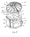
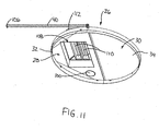
- the device includes a housing locating a composting chamber 12 therein.
- the composting chamber is a cylindrical upright chamber having cylindrical side walls 14 and a floor 16 which is generally conical in shape tapering downwardly and inwardly to a bottom end of the composting chamber.
- a frame 18 supports the composting chamber spaced upwardly from the ground to define a control area 20 therebelow.
- the frame 18 includes an annular base 22 for being supported on the ground. Uprights 24 span vertically between the base 22 and the floor 16 of the composting chamber at spaced positions about a circumference of the annular base 22.
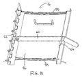
- the cylindrical walls 14 of the composting chamber support a lid 26 thereon.
- the lid is also generally conical in shape so as to taper inwardly and upwardly towards a top end of the composting device.
- the lid 26 includes a fixed portion 28 and a movable portion 30 which divide the generally conical shape of the lid into two diametrically opposed halves.
- the movable portion 30 is slightly larger in dimension than the fixed portion 28 so as to permit the fixed portion 28 to be nested within the movable portion when the movable portion is rotated 180 degrees about a central vertical axis of the composter device to overlap the fixed portion in an open position of the lid.
- Each of the fixed and movable portions of the lid includes a frame 32 composed of rigid frame members about the periphery and spanning the interior thereof as well as an insulation panel 34 which encloses the panel and fully spans the frame 32.
- the frame of the fixed portion 28 is fixed on the top side of the cylindrical walls of the composting chamber.
- the movable portion is pivoted at an apex of the lid 26 and remains slidable at the periphery on an annular frame member 36 encircling the top end of the cylindrical walls 14 and also supporting the fixed portion 28 of the lid thereon.
- Sealing material is provided at the intersection of the movable portion and the fixed portion as well as about the peripheral edge of the movable portion to fully enclose the top end of the composter device when the fixed and movable portions are positioned side by side in the conical configuration illustrated in Figure 1.
- a handle 40 is secured to the frame of the movable portion 30 of the lid to extend outwardly and downwardly along side the composter device to a free end spaced above the ground which can be readily grasped by an operator of the composter device. Opening and closing of the lid is thus accomplished by sliding the movable portion 30 over top of the fixed portion by manually engaging the handle 40 and walking about a circumference of the composter device approximately 180 degrees.
- the annular frame member 36 about the top of the.cylindrical walls of the composting chamber and the annular base 22 of the frame of the composter device each include a suitable retaining flange 42 for retaining a cylindrical wall of insulation 44 which fully surrounds the composter device 10. Both the control area and the composting chamber thereabove are surrounded by the insulation 44.
- An access door 46 is located in a side of the composter device for communication through the wall of insulation 44 to access the interior of the control area.
- the access door is similarly formed with frame members and insulation spanning thereacross.
- Hinges 48 are provided on one side of the door while latches 50 on the opposing side secure the door in a closed position.
- a discharge chutee 52 communicates through the wall of insulation 44 below the composting chamber and diametrically opposite to the access door 46.
- the discharge chutee is an inclined trough extending at a downward and inward incline along a bottom side of the conical floor 16 of the composting chamber from an outlet hatch 54 supported in the wall of insulation 44 to a door 56 formed in the floor 16 of the composting chamber adjacent the bottom end thereof.
- the door 56 generally comprises a rigid rectangular panel which fits over the door opening formed in the floor with the edges of the panel overlapping the outer surface of the floor with a sealing material 58 engaged between the panel and the floor.
- the panel is held frictionally engaged against the door opening by a latch bar 60 arranged to permit the door 56 to be removed when the latch is released.
- the latch bar 60 generally comprises an elongate bar which is pivoted to a hinge 62 extending along one side of the door opening.
- the latch bar 60 is of suitable length to span the width of the door panel for being selectively received by a retaining lug 64 on an opposing side of the door opening when in a closed position.
- a cover 65 mounts at the opening of the discharge chutee through the wall of insulation 44.
- the cover 65 includes rigid frame elements and insulating materials spanning thereacross in a construction similar to the previously noted external components of the composter device.
- the discharge chutee 52 is suitably sized to receive the feed end of a discharge auger therein for unloading the composter device with an auger as desired.
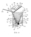
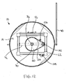
- Components of a mixer 66 and a grinder 68 are supported on a working shaft 70 of the composter device.
- the working shaft extends vertically through a center of the composter device, co-axially with the walls of the composting chamber and the conical floor 16.
- a cross beam 72 spans diametrically across a top end of the composting chamber for pivotally supporting a top end of the working shaft 70 therein.
- a flat circular base plate 74 is mounted at the bottom of the conical floor 16 so that the door 56 of the discharge chutee is positioned directly adjacent the base plate.
- Suitable bearings 76 are supported in the base plate 74 for centrally locating the bottom end of the working shaft 70 to extend therethrough.
- the mixer 66 generally comprises an auger flighting 78 fixed about the shaft for rotation therewith.
- the flighting spirals upwardly from a bottom end directly adjacent the base plate 74 to a top end terminating at an intermediate point in a height of the composting chamber.
- Rotation of the working shaft 70 is oriented to urge material in the composting chamber upwardly at a center of the chamber along the mixer 66 in a working direction of the rotation of the shaft.
- the overall diameter of the flighting 78 is small in relation to the diameter of the composting chamber 12.
- a plurality of blades 80 are positioned at spaced positions about the periphery of the flighting 78. Each blade is secured by threaded fasteners to the flighting spaced circumferentially approximately 90 degrees from adjacent ones of the blades 80. In the first illustrated embodiment, the blades project forwardly and outwardly into the direction of rotation however due to the threaded connection of the blades to the flighting, blades of varying aggressive angles relative to the direction of rotation may be provided and replaced as desired.
- the grinder 68 includes a first grinding element 82 which is mounted on the working shaft 70 for rotation with the flighting in the shaft directly below the mixer at the bottom end of the flighting and directly adjacent the base plate 74.
- the first grinding element 82 thus comprises a rigid bar having a bottom edge 84 which rides along the base plate 74 which is fixed in position at the bottom of the composting chamber 12.
- a set of horizontal slots 86 are provided along the bottom edge to provide an opening at each slot between the grinding element 82 and the plate.
- At least one vertical slot 88 is also provided and intersects one of the horizontal slots 86 in the illustrated embodiment.
- a plurality of second grinding elements 90 remain fixed on the base plate 74 for co-operation with the slots 86 and 88 formed in the first grinding element 82.
- Each second grinding element 90 comprises a fixed lug in radial alignment, relative to the working shaft, with the horizontal slots 86 and vertical slot 88 respectively.
- the lugs are suitably sized for a close tolerance fit between the edges of the second grinding elements 90 and the slots formed in the first grinding element 82 to produce a shearing action therebetween when the first grinding element is rotated with the shaft relative to the second grinding elements which remain fixed on the base plate.
- the second grinding elements 90 are located at spaced circumferential positions about the shaft for being received through respective slots in the first grinding element at different points of rotation thereof.
- a vertical grinding element 92 is provided fixed on the base plate 74 for alignment with the vertical slot 88 and includes a sharpened knife edge which confronts the first grinding element 82 at an upward incline towards the first grinding element as the first grinding element is moving towards the vertical grinding element 92 in operation.
- the inclined edge provides some grip to retain matter to be crushed, for example bones from an animal carcass, during a grinding cycle of the composter device.
- Guide teeth 94 are supported at spaced positions on the first grinding element to project into the direction of travel above the slots 86.
- a forward facing leading edge of the guide teeth 94 projects at a downwardly and inward incline towards the first grinding element for guiding material to be ground downwardly into the slots of the first grinding element. Accordingly as the first grinding element is rotated the matter urged in front of the slots 86 and 88 are crushed by the shearing action of the second grinding elements fixed on the plate rotated through the slots.
- the flighting 78 of the mixer 66 and the first grinding element 82 of the grinder 68 are commonly driven on the working shaft 70 which projects below the base plate 74 through the bearing 76 to a bottom end within the control area 20 where a horizontal driven gear 100 is supported on the shaft.
- the driven gear is coupled to a driving gear 102 by a suitable drive chain 104.
- An idler gear 106 is provided on a chain tightener to remove slack from the drive chain 104 coupling the driving gear 102 to the driven gear 100.
- a motor 108 drives a gearbox 110 coupled to the driving gear 102 to provide suitable torque for driving rotation of the grinder to crush matter including bones of an animal carcass and the like.
- the control area also locates heating elements (not shown), an air pump (not shown) and a water supply (not shown) for providing heat, fresh air and moisture to the interior of the composting chamber as required to maintain optimum conditions for composting therein.
- Activation of the air pump provides fresh oxygen for micro-organisms in the composting chamber to consume and assist in the decomposition process.
- Pumping fresh air into the composting chamber can also affect temperature within the chamber by cooling the compost mixture or by accelerating the decomposition process which produces heat.
- the heating elements, the air pump and water supply are conventional equipment that work in co-operation with commercially available temperature, oxygen and moisture sensors (not shown) respectively located in the composting chamber which provide information to a suitable controller (not shown) which respectively determines activation of the heating elements, activation of the air pump and dispensing of water through nozzles of the water supply. This ensures sufficient heat, oxygen and moisture to optimize the decomposition of the matter to be composted by micro-organisms.
- the controller also controls activation of the motor 108 to provide periodic activation of the mixer 66 to circulate the material in the composting chamber to improve air circulation and evenly distribute micro-organisms to further optimize the composting process.
- the air pump alone may be used to control either the temperature or the moisture content by activation of the air pump in response to detection by a thermostat that temperature is not within an ideal range or that too much moisture is present such that the matter to be composted requires drying.
- the device 10 similarly comprises a housing locating a composting chamber 12 therein.
- the chamber in this instance is generally conical in shape in which the side walls 14 are sloped downwardly and inwardly continuous with the floor to the bottom end of the composting chamber.
- the frame 18 similarly supports the composting chamber above a base 22 supported on the ground. Accordingly a similar control area 20 is provided below the compositing chamber for supporting operating components of the composter device.
- the uprights 24 of the frame span vertically between the base and the walls 14 of the composting chamber at circumferentially spaced positions about the chamber.
- the walls 14 of the composting chamber similarly support the lid 26 thereon which is round in shape to span the top end of the composting device.
- the lid according to the second embodiment also includes the fixed portion 28 and the movable portion 30 which divide the lid into two diametrically opposed halves in which the fixed portion remains fixed relative the housing while the movable portion 30 is pivoted into an open position.
- the movable portion 30 is hinged relative to the fixed portion along a diametrically and horizontally extending hinge so that the movable portion is pivoted upwardly into the open position.
- Each of the fixed and movable portions 28 and 30 of the lid includes a peripheral frame 32 composed of rigid members and a panel 34 enclosing the lid which is insulated. Sealing material is provided at an intersection of the movable portion with the fixed portion and the open top edges of the composting chamber to fully enclose the top end to the composter device when fixed and movable portions are positioned side by side as shown in the accompanying Figures.
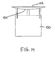
- a vent 100 is provided on the fixed portion of the lid to vent excess heat and moisture from the composting chamber during the composting process.
- the vent 100 generally comprises an upright collar in communication with a through opening in the fixed portion of the lid which includes an open top end.
- a lid member 102 which is generally circular of equal or greater diameter than the collar, is positioned directly above the open top end of the collar spaced slightly thereabove to define a gap through which air can be vented.
- the lid member 102 includes a domed inner surface 104 which is convex in profile so that moisture condensing thereon is encouraged to drip toward the center of the lid member 102 for falling back into the composting chamber rather than accumulating as ice on the lid member in colder climates.
- the lid member 102 is supported spaced above the collar defining the vent 100 by suitable leg members at circumferentially spaced positions there about.
- the handle 40 comprises an elongate arm which is fixed onto the movable portion 30 of the lid to extend horizontally outward from the movable portion towards the fixed portion, perpendicularly to the hinge, adjacent one end thereof and spaced radially outward sufficiently that the handle clears the housing of the composting chamber when it is pivoted downwardly.
- the handle 40 lies on a common plane with the movable portion so that the movable portion is pivoted upwardly into the open position as the handle is pulled downwardly at the free end 106.
- a suitable rope or chain may be connected to the free end 106 for being suspended therefrom in such a manner that the handle is more readily grasped by a person trying to open the lid while standing on the ground.
- a heater 108 is supported in the fixed portion of the lid at the top end of the composting chamber.
- the heater 108 includes a pair of heating elements 110 which are supported within an external housing 112 of the heater for communication through an opening in the fixed portion of the lid to which the exterior housing 112 is sealed.
- the external housing 112 includes a hinged access panel 114 which permits access to the heating elements 110 from an external side of the lid so that the heating elements can be readily serviced as desired.
- Location of the heater in the lid at the top end of the composting chamber protects the components of the heating elements from damage due to the churning material to be composted.
- the insulation 44 is sprayed on in the second embodiment to provide a full coating about the exterior of the housing for maintaining heat within the composting chamber in colder climates.
- the second embodiment also includes the discharge chute 52 which communicates through the wall of insulation 44 to communicate with the bottom discharge opening in the wall of the composting chamber.
- the chute extends downward and outward at an incline from the conical shaped wall 14 adjacent the bottom side thereof.
- a door 56 is similarly provided for closing the discharge chute.
- the door 56 according to the second embodiment comprises a one piece plug including a flush interior panel 116, a tubular body for being slidably received in the discharge chute and an outer rim flange 118.
- the outer rim flange 118 sandwiches a layer of rubber sealing material between itself and a cooperating flange at the free end of the discharge chute.
- Suitable clamping members are provided at circumferentially spaced position about the outer flange 18 for clamping the rubber sealing material between the door 56 and the discharge chute 52 which the door encloses.
- the flush interior panel 116 is flush with the opening formed in the wall 14 of the composting chamber.
- the second embodiment similarly includes the mixer 66 and the grinder 68 which are supported on the working shaft 70 for rotation together about a vertical axis extending through the center of the floor of the composter device co-axially with the conical walls of the composting chamber.
- the cross beam 72 in the second embodiment spans diametrically across the base 22 of the device for pivotally supporting the free bottom end 120 of the working shaft 70.
- a flat circular base plat 74 is similarly mounted above the shaft at the bottom of the composting chamber, but at the top end of the working shaft 70. Suitable bearings 76 and a sealing member are similarly supported in the base plate 74 for centrally locating the working shaft therethrough in sealing engagement about the shaft.
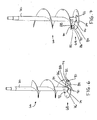
- the mixer 66 generally comprises a sweep arm 122 fixed to the shaft 70 for rotation therewith.
- the arm 122 spirals upwardly from a bottom end directly adjacent the base plate 74 to a top end terminating at an intermediate point in a height of the composting chamber in a direction which slopes upwardly and away from the direction of rotation in operation.
- the sweep arm 122 is adjacent the peripheral wall of the composting chamber throughout the length thereof from a gap of approximately one quarter of an inch adjacent the base plate 74 to a maximum gap of approximately one and a half inches adjacent the free top end thereof.
- Rotation of the working shaft 70 is similarly oriented to urge material in the composting chamber upwardly at a periphery of the chamber along the mixer 66 in a working direction of the shaft rotation.
- the overall diameter of the rod forming the sweep arm 122 is approximately three inches so as to be considerably smaller in size and relation to the diameter of the composting chamber 12.
- a ramp bar 124 is mounted at a fixed position on the peripheral wall of the composing chamber at an intermediate position along the length of the sweep arm 22
- the ramp bar 124 is an elongate member extending circumferentially partway about the composting chamber so as to slope upwardly in the direction of the sweep arm 122 sweeping past the bar 124.
- the bar has a thickness in the order of one inch to substantially fill the gap between the sweep arm 122 and the peripheral wall of the composing chamber at a point of contact therebetween.
- the components of the grinder 68 in the second embodiment are substantially identical to those of the first embodiment in which first grinding elements are mounted on the working shaft 70 for rotation with the mixer, below the mixer, at the bottom end of the composting chamber directly adjacent the base plate 74.
- the first grinding element 82 generally comprises a rigid plate extending radially outward in an upright orientation which supports the sweep arm 122 thereon.
- a suitable gusset is provided at a trailing side of the grinding element 82 for providing additional structural support to the sweep arm 122.
- Slots 86 and 88 are similarly provided along the bottom edge of the first grinding element for cooperation with second grinding elements 90 which remain fixed on the base plate 74 as described in accordance with the first embodiment.
- the second grinding elements similarly comprise lugs which produce a sheering action when the slots of the first grinding element are rotated past the second grinding elements.
- the second grinding elements are located at spaced circumferential positions about the shaft.
- a plurality of vertical grinding elements 92 are also provided, each having a knife edge inclined upwardly into the direction of rotation to confront the first grinding element as described above.
- Guide teeth 94 are also provided on the first grinding element as described above with regard to the first embodiment.
- the sweep arm 122 and the first grinding element are commonly driven on the working shaft 70 by the horizontal driven gear 100 supported on the shaft below the base plate 74.
- a driving gear 102, a drive chain 104 and the idler gear 106 of the first embodiment are all similarly arranged for being driven by a motor 108 and gear box combination.
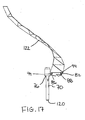
- FIG 17 a further embodiment of the sweep arm 122 is illustrated which similarly spirals upwardly adjacent a periphery of the composting chamber walls to be sloped upwardly and away from the direction of rotation of the shaft.
- the sweep arm 122 according to the embodiment of Figure 17 comprises a broad plate member, as opposed to a solid rod, which is close in tolerance to the wall of the composting chamber to provide a minimum gap therebetween.
- the broad flat surface assists in churning the material to be composted by encouraging the material to ride up the broad flat surface of the sweep arm 122 as the arm is rotated about the periphery of the composting chamber. No ramp bar is thus required in this instance.
- various control features maybe provided for controlling the amount of air, water and heat provided to the material to be composted.
- the vent 100 for instance, maybe provided with a closable lid which is selectively opened only when excess heat is to be removed at selected times during the composting process.
- the lid 26 of the composter device is first opened to permit loading of the composting chamber through the opening formed in the top end of the device.
- Material to be composted may include various types of organic matter.
- additional cellulose fibre or material in the form of straw or sawdust is added along with any moisture required so that the desired mixture has a moisture approximately in the range of 50%.
- the lid is closed and sealed shut and the grinding operation begins by steadily rotating the working shaft with the first grinding element supported thereon for a prescribed period of time until the matter to be composted is sufficiently ground into a ground material having a particle size which is sufficiently reduce to optimize the composting process.
- Rotation of the working shaft can then be stopped to permit the material to be composted to remain in the composting chamber for decomposition.
- moisture levels and temperature are periodically checked automatically by the controller. An ideal temperature range is maintained between 130 and 150 degrees Fahrenheit.
- the compositing period in which the matter remains in the composting chamber for decomposition is typically in the order of approximately 100 hours during which the motor is periodically activated to rotate the mixer 66 to stir the ground matter to be composted so that air is circulated through the mixture.
- the periodic intervals of stirring by the mixer are preset again for optimized decomposition.
Landscapes
- Chemical & Material Sciences (AREA)
- Chemical Kinetics & Catalysis (AREA)
- Life Sciences & Earth Sciences (AREA)
- Engineering & Computer Science (AREA)
- Biochemistry (AREA)
- Biotechnology (AREA)
- Health & Medical Sciences (AREA)
- General Chemical & Material Sciences (AREA)
- Microbiology (AREA)
- Molecular Biology (AREA)
- Organic Chemistry (AREA)
- Fertilizers (AREA)
- Processing Of Solid Wastes (AREA)
Applications Claiming Priority (2)
| Application Number | Priority Date | Filing Date | Title |
|---|---|---|---|
| CA2441658A CA2441658C (en) | 2003-09-19 | 2003-09-19 | Device and method for composting |
| CA2441658 | 2003-09-19 |
Publications (2)
| Publication Number | Publication Date |
|---|---|
| EP1520845A1 true EP1520845A1 (de) | 2005-04-06 |
| EP1520845B1 EP1520845B1 (de) | 2012-03-07 |
Family
ID=34280688
Family Applications (1)
| Application Number | Title | Priority Date | Filing Date |
|---|---|---|---|
| EP04022142A Expired - Lifetime EP1520845B1 (de) | 2003-09-19 | 2004-09-17 | Vorrichtung und Verfahren zur Kompostierung |
Country Status (5)
| Country | Link |
|---|---|
| US (1) | US20050061044A1 (de) |
| EP (1) | EP1520845B1 (de) |
| AT (1) | ATE548342T1 (de) |
| CA (1) | CA2441658C (de) |
| ES (1) | ES2382801T3 (de) |
Cited By (1)
| Publication number | Priority date | Publication date | Assignee | Title |
|---|---|---|---|---|
| US5500477A (en) * | 1992-10-03 | 1996-03-19 | Hoechst Aktiengesellschaft | Polyacetal molding materials having high impact resistance, a process for their preparation, and their use |
Families Citing this family (11)
| Publication number | Priority date | Publication date | Assignee | Title |
|---|---|---|---|---|
| US8649858B2 (en) * | 2007-06-25 | 2014-02-11 | Boston Scientific Neuromodulation Corporation | Architectures for an implantable medical device system |
| US20090145188A1 (en) * | 2007-12-07 | 2009-06-11 | Halton Recycling Limited | Apparatus and methods for generating compost |
| CA2749752A1 (en) * | 2009-01-16 | 2010-07-22 | Siemens Industry, Inc. | Amendment-free sludge composting |
| FR2946643B1 (fr) * | 2009-06-12 | 2018-04-20 | Evy Dutheil | Procede de recyclage et de revalorisation de dechets menagers ainsi que dispositif adapte a la mise en oeuvre de ce procede. |
| WO2013044984A1 (de) * | 2011-09-30 | 2013-04-04 | Bühler AG | Vorrichtung und verfahren zum weichen, keimen, darren, fermentieren und/oder kombinationen daraus von korn |
| US9895726B1 (en) | 2016-07-27 | 2018-02-20 | Whirlpool Corporation | Method for cleaning a food waste recycling bin of a food waste recycling appliance |
| USD1027351S1 (en) | 2016-03-09 | 2024-05-14 | Whirlpool Corporation | Food recycler |
| US20180029948A1 (en) * | 2016-07-27 | 2018-02-01 | Whirlpool Corporation | Food waste recycler with mixing assembly |
| RU2632162C1 (ru) * | 2016-06-14 | 2017-10-02 | Федеральное Государственное бюджетное научное учреждение Институт агроинженерных и экологических проблем в сельскохозяйственном производстве (ИАЭП) | Универсальный биоферментатор |
| RU191290U1 (ru) * | 2019-03-06 | 2019-08-01 | Федеральное государственное бюджетное образовательное учреждение высшего образования "Кубанский государственный аграрный университет им. И.Т. Трубилина" | Установка биологической переработки птичьего помета |
| WO2021242126A1 (es) * | 2020-05-26 | 2021-12-02 | Grupo Gaan Servicios Generales E.I.R.L | Aparato contenedor de desechos orgánicos que produce compost |
Citations (5)
| Publication number | Priority date | Publication date | Assignee | Title |
|---|---|---|---|---|
| US3845939A (en) | 1972-12-06 | 1974-11-05 | Waste Treat Inc | Composting apparatus |
| US4169878A (en) | 1978-01-10 | 1979-10-02 | Etherington Alfred B | Helical composter |
| WO1997037783A1 (en) | 1996-04-04 | 1997-10-16 | Tomoyasu Tokuyama | Raw refuse disposer |
| EP1264644A1 (de) | 1999-05-07 | 2002-12-11 | Yasuichi Ueda | Abfallentsorgungsvorrichtung |
| WO2004029001A1 (en) | 2002-09-27 | 2004-04-08 | Biosys Pty Ltd | Organic waste treatment apparatus |
Family Cites Families (15)
| Publication number | Priority date | Publication date | Assignee | Title |
|---|---|---|---|---|
| US3353508A (en) * | 1965-08-19 | 1967-11-21 | Wylie W Crowe | Garbage destroyer |
| US3850364A (en) * | 1973-08-15 | 1974-11-26 | R Robbins | Portable compost grinding apparatus |
| FI100051B (fi) * | 1992-02-18 | 1997-09-15 | Favorit Oy | Kompostori |
| ES2125365T3 (es) * | 1993-04-09 | 1999-03-01 | Matsushita Electric Industrial Co Ltd | Maquina para el tratamiento de residuos. |
| JPH07124538A (ja) * | 1993-11-01 | 1995-05-16 | Hitachi Ltd | 固形有機廃棄物の処理装置 |
| US5687918A (en) * | 1994-03-15 | 1997-11-18 | Kabushiki Kaisha Toshiba | Garbage disposal |
| FI98301C (fi) * | 1994-05-18 | 1997-05-26 | Biolan Oy | Kaksivaiheinen rumpukompostori |
| JP3228065B2 (ja) * | 1995-05-19 | 2001-11-12 | 株式会社日立製作所 | 生ごみ処理装置 |
| US5948674A (en) * | 1996-01-11 | 1999-09-07 | The Gaia Institute, Inc. | Organic waste composting system |
| US5744351A (en) * | 1996-05-22 | 1998-04-28 | Bryan-Brown; Michael | Apparatus for compositing organic waste |
| NZ337895A (en) * | 1997-03-27 | 2001-07-27 | Pei Technology Ltd | Apparatus and method for mixing cementitious materials |
| US5890664A (en) * | 1997-07-22 | 1999-04-06 | Conant, Iii; Jess Austin | Transportable, self-contained, fully automated composter |
| US6653123B2 (en) * | 1999-12-28 | 2003-11-25 | Tsukuba Food Science, Inc. | Process for producing processed organic product and apparatus therefor |
| EP1135983B1 (de) * | 2000-03-17 | 2003-05-07 | SANCASSIANO S.p.A. | Spiralförmige Knetmaschine mit nichtverdrehbarem Behälter zur Zubereitung von Gemisch auf Mehlbasis |
| US6609821B2 (en) * | 2001-04-13 | 2003-08-26 | Sunbeam Products, Inc. | Blender base with food processor capabilities |
-
2003
- 2003-09-19 CA CA2441658A patent/CA2441658C/en not_active Expired - Lifetime
-
2004
- 2004-09-17 AT AT04022142T patent/ATE548342T1/de active
- 2004-09-17 EP EP04022142A patent/EP1520845B1/de not_active Expired - Lifetime
- 2004-09-17 ES ES04022142T patent/ES2382801T3/es not_active Expired - Lifetime
- 2004-09-20 US US10/944,276 patent/US20050061044A1/en not_active Abandoned
Patent Citations (5)
| Publication number | Priority date | Publication date | Assignee | Title |
|---|---|---|---|---|
| US3845939A (en) | 1972-12-06 | 1974-11-05 | Waste Treat Inc | Composting apparatus |
| US4169878A (en) | 1978-01-10 | 1979-10-02 | Etherington Alfred B | Helical composter |
| WO1997037783A1 (en) | 1996-04-04 | 1997-10-16 | Tomoyasu Tokuyama | Raw refuse disposer |
| EP1264644A1 (de) | 1999-05-07 | 2002-12-11 | Yasuichi Ueda | Abfallentsorgungsvorrichtung |
| WO2004029001A1 (en) | 2002-09-27 | 2004-04-08 | Biosys Pty Ltd | Organic waste treatment apparatus |
Cited By (1)
| Publication number | Priority date | Publication date | Assignee | Title |
|---|---|---|---|---|
| US5500477A (en) * | 1992-10-03 | 1996-03-19 | Hoechst Aktiengesellschaft | Polyacetal molding materials having high impact resistance, a process for their preparation, and their use |
Also Published As
| Publication number | Publication date |
|---|---|
| US20050061044A1 (en) | 2005-03-24 |
| ATE548342T1 (de) | 2012-03-15 |
| CA2441658A1 (en) | 2005-03-19 |
| EP1520845B1 (de) | 2012-03-07 |
| ES2382801T3 (es) | 2012-06-13 |
| CA2441658C (en) | 2011-01-11 |
Similar Documents
| Publication | Publication Date | Title |
|---|---|---|
| US8298312B2 (en) | Device and method for composting | |
| US3845939A (en) | Composting apparatus | |
| EP1520845A1 (de) | Vorrichtung und Verfahren zur Kompostierung | |
| CA2425044C (en) | A composting apparatus with internal transport system | |
| CN107594591A (zh) | 饲料粉碎加工及烘干处理装置 | |
| US20160122255A1 (en) | An organic waste composter and a method of composting organic waste material | |
| EP1264644A1 (de) | Abfallentsorgungsvorrichtung | |
| US7138271B2 (en) | Continuous composter | |
| CN114213170A (zh) | 一种利用园林废弃物制备肥料的装置及方法 | |
| JP4880821B2 (ja) | 撹拌粉砕装置 | |
| KR200197406Y1 (ko) | 발효 사료 제조 장치 | |
| CA2435017C (en) | Continuous composter | |
| JP2007210832A (ja) | 有機廃棄物処理装置 | |
| CN220351131U (zh) | 一种塞盘干料系统自动添加微量元素的装置 | |
| CN219580482U (zh) | 一种添加连续湿法制粒机 | |
| WO2002020430A1 (en) | In-vessel composting apparatus and method for waste management and soil enhancement | |
| CN217077439U (zh) | 一种利用园林废弃物制备肥料的装置 | |
| CN219437875U (zh) | 一种一体式畜牧养殖喂食装置 | |
| JP3700086B2 (ja) | 混練物の造粒方法および造粒装置 | |
| JP2008086915A (ja) | 生ゴミ処理装置 | |
| CN214915825U (zh) | 一种有机肥原料造粒装置 | |
| JP3494846B2 (ja) | 生ごみ処理装置 | |
| CN2755093Y (zh) | 含水垃圾处理装置 | |
| JPS6355976B2 (de) | ||
| CN115536458A (zh) | 一种肥料加工机 |
Legal Events
| Date | Code | Title | Description |
|---|---|---|---|
| PUAI | Public reference made under article 153(3) epc to a published international application that has entered the european phase |
Free format text: ORIGINAL CODE: 0009012 |
|
| AK | Designated contracting states |
Kind code of ref document: A1 Designated state(s): AT BE BG CH CY CZ DE DK EE ES FI FR GB GR HU IE IT LI LU MC NL PL PT RO SE SI SK TR |
|
| AX | Request for extension of the european patent |
Extension state: AL HR LT LV MK |
|
| 17P | Request for examination filed |
Effective date: 20051006 |
|
| AKX | Designation fees paid |
Designated state(s): AT BE BG CH CY CZ DE DK EE ES FI FR GB GR HU IE IT LI LU MC NL PL PT RO SE SI SK TR |
|
| 17Q | First examination report despatched |
Effective date: 20051117 |
|
| GRAP | Despatch of communication of intention to grant a patent |
Free format text: ORIGINAL CODE: EPIDOSNIGR1 |
|
| GRAS | Grant fee paid |
Free format text: ORIGINAL CODE: EPIDOSNIGR3 |
|
| GRAA | (expected) grant |
Free format text: ORIGINAL CODE: 0009210 |
|
| AK | Designated contracting states |
Kind code of ref document: B1 Designated state(s): AT BE BG CH CY CZ DE DK EE ES FI FR GB GR HU IE IT LI LU MC NL PL PT RO SE SI SK TR |
|
| REG | Reference to a national code |
Ref country code: GB Ref legal event code: FG4D |
|
| REG | Reference to a national code |
Ref country code: CH Ref legal event code: EP Ref country code: AT Ref legal event code: REF Ref document number: 548342 Country of ref document: AT Kind code of ref document: T Effective date: 20120315 |
|
| REG | Reference to a national code |
Ref country code: IE Ref legal event code: FG4D |
|
| REG | Reference to a national code |
Ref country code: DE Ref legal event code: R096 Ref document number: 602004036767 Country of ref document: DE Effective date: 20120503 |
|
| REG | Reference to a national code |
Ref country code: ES Ref legal event code: FG2A Ref document number: 2382801 Country of ref document: ES Kind code of ref document: T3 Effective date: 20120613 |
|
| REG | Reference to a national code |
Ref country code: NL Ref legal event code: VDEP Effective date: 20120307 |
|
| PG25 | Lapsed in a contracting state [announced via postgrant information from national office to epo] |
Ref country code: NL Free format text: LAPSE BECAUSE OF FAILURE TO SUBMIT A TRANSLATION OF THE DESCRIPTION OR TO PAY THE FEE WITHIN THE PRESCRIBED TIME-LIMIT Effective date: 20120307 |
|
| PG25 | Lapsed in a contracting state [announced via postgrant information from national office to epo] |
Ref country code: GR Free format text: LAPSE BECAUSE OF FAILURE TO SUBMIT A TRANSLATION OF THE DESCRIPTION OR TO PAY THE FEE WITHIN THE PRESCRIBED TIME-LIMIT Effective date: 20120608 Ref country code: FI Free format text: LAPSE BECAUSE OF FAILURE TO SUBMIT A TRANSLATION OF THE DESCRIPTION OR TO PAY THE FEE WITHIN THE PRESCRIBED TIME-LIMIT Effective date: 20120307 |
|
| REG | Reference to a national code |
Ref country code: AT Ref legal event code: MK05 Ref document number: 548342 Country of ref document: AT Kind code of ref document: T Effective date: 20120307 |
|
| PG25 | Lapsed in a contracting state [announced via postgrant information from national office to epo] |
Ref country code: CY Free format text: LAPSE BECAUSE OF FAILURE TO SUBMIT A TRANSLATION OF THE DESCRIPTION OR TO PAY THE FEE WITHIN THE PRESCRIBED TIME-LIMIT Effective date: 20120307 |
|
| PG25 | Lapsed in a contracting state [announced via postgrant information from national office to epo] |
Ref country code: CZ Free format text: LAPSE BECAUSE OF FAILURE TO SUBMIT A TRANSLATION OF THE DESCRIPTION OR TO PAY THE FEE WITHIN THE PRESCRIBED TIME-LIMIT Effective date: 20120307 Ref country code: EE Free format text: LAPSE BECAUSE OF FAILURE TO SUBMIT A TRANSLATION OF THE DESCRIPTION OR TO PAY THE FEE WITHIN THE PRESCRIBED TIME-LIMIT Effective date: 20120307 Ref country code: RO Free format text: LAPSE BECAUSE OF FAILURE TO SUBMIT A TRANSLATION OF THE DESCRIPTION OR TO PAY THE FEE WITHIN THE PRESCRIBED TIME-LIMIT Effective date: 20120307 Ref country code: PL Free format text: LAPSE BECAUSE OF FAILURE TO SUBMIT A TRANSLATION OF THE DESCRIPTION OR TO PAY THE FEE WITHIN THE PRESCRIBED TIME-LIMIT Effective date: 20120307 Ref country code: SI Free format text: LAPSE BECAUSE OF FAILURE TO SUBMIT A TRANSLATION OF THE DESCRIPTION OR TO PAY THE FEE WITHIN THE PRESCRIBED TIME-LIMIT Effective date: 20120307 Ref country code: SE Free format text: LAPSE BECAUSE OF FAILURE TO SUBMIT A TRANSLATION OF THE DESCRIPTION OR TO PAY THE FEE WITHIN THE PRESCRIBED TIME-LIMIT Effective date: 20120307 Ref country code: BE Free format text: LAPSE BECAUSE OF FAILURE TO SUBMIT A TRANSLATION OF THE DESCRIPTION OR TO PAY THE FEE WITHIN THE PRESCRIBED TIME-LIMIT Effective date: 20120307 |
|
| PG25 | Lapsed in a contracting state [announced via postgrant information from national office to epo] |
Ref country code: SK Free format text: LAPSE BECAUSE OF FAILURE TO SUBMIT A TRANSLATION OF THE DESCRIPTION OR TO PAY THE FEE WITHIN THE PRESCRIBED TIME-LIMIT Effective date: 20120307 Ref country code: PT Free format text: LAPSE BECAUSE OF FAILURE TO SUBMIT A TRANSLATION OF THE DESCRIPTION OR TO PAY THE FEE WITHIN THE PRESCRIBED TIME-LIMIT Effective date: 20120709 |
|
| PLBE | No opposition filed within time limit |
Free format text: ORIGINAL CODE: 0009261 |
|
| STAA | Information on the status of an ep patent application or granted ep patent |
Free format text: STATUS: NO OPPOSITION FILED WITHIN TIME LIMIT |
|
| PG25 | Lapsed in a contracting state [announced via postgrant information from national office to epo] |
Ref country code: AT Free format text: LAPSE BECAUSE OF FAILURE TO SUBMIT A TRANSLATION OF THE DESCRIPTION OR TO PAY THE FEE WITHIN THE PRESCRIBED TIME-LIMIT Effective date: 20120307 Ref country code: DK Free format text: LAPSE BECAUSE OF FAILURE TO SUBMIT A TRANSLATION OF THE DESCRIPTION OR TO PAY THE FEE WITHIN THE PRESCRIBED TIME-LIMIT Effective date: 20120307 |
|
| 26N | No opposition filed |
Effective date: 20121210 |
|
| REG | Reference to a national code |
Ref country code: DE Ref legal event code: R097 Ref document number: 602004036767 Country of ref document: DE Effective date: 20121210 |
|
| PG25 | Lapsed in a contracting state [announced via postgrant information from national office to epo] |
Ref country code: MC Free format text: LAPSE BECAUSE OF NON-PAYMENT OF DUE FEES Effective date: 20120930 |
|
| REG | Reference to a national code |
Ref country code: CH Ref legal event code: PL |
|
| REG | Reference to a national code |
Ref country code: IE Ref legal event code: MM4A |
|
| PG25 | Lapsed in a contracting state [announced via postgrant information from national office to epo] |
Ref country code: IE Free format text: LAPSE BECAUSE OF NON-PAYMENT OF DUE FEES Effective date: 20120917 Ref country code: BG Free format text: LAPSE BECAUSE OF FAILURE TO SUBMIT A TRANSLATION OF THE DESCRIPTION OR TO PAY THE FEE WITHIN THE PRESCRIBED TIME-LIMIT Effective date: 20120607 Ref country code: LI Free format text: LAPSE BECAUSE OF NON-PAYMENT OF DUE FEES Effective date: 20120930 Ref country code: CH Free format text: LAPSE BECAUSE OF NON-PAYMENT OF DUE FEES Effective date: 20120930 |
|
| PG25 | Lapsed in a contracting state [announced via postgrant information from national office to epo] |
Ref country code: TR Free format text: LAPSE BECAUSE OF FAILURE TO SUBMIT A TRANSLATION OF THE DESCRIPTION OR TO PAY THE FEE WITHIN THE PRESCRIBED TIME-LIMIT Effective date: 20120307 |
|
| PG25 | Lapsed in a contracting state [announced via postgrant information from national office to epo] |
Ref country code: LU Free format text: LAPSE BECAUSE OF NON-PAYMENT OF DUE FEES Effective date: 20120917 |
|
| PG25 | Lapsed in a contracting state [announced via postgrant information from national office to epo] |
Ref country code: HU Free format text: LAPSE BECAUSE OF FAILURE TO SUBMIT A TRANSLATION OF THE DESCRIPTION OR TO PAY THE FEE WITHIN THE PRESCRIBED TIME-LIMIT Effective date: 20040917 |
|
| REG | Reference to a national code |
Ref country code: FR Ref legal event code: PLFP Year of fee payment: 13 |
|
| REG | Reference to a national code |
Ref country code: FR Ref legal event code: PLFP Year of fee payment: 14 |
|
| PGFP | Annual fee paid to national office [announced via postgrant information from national office to epo] |
Ref country code: IT Payment date: 20170926 Year of fee payment: 14 Ref country code: GB Payment date: 20170921 Year of fee payment: 14 Ref country code: DE Payment date: 20170928 Year of fee payment: 14 Ref country code: FR Payment date: 20170928 Year of fee payment: 14 |
|
| PGFP | Annual fee paid to national office [announced via postgrant information from national office to epo] |
Ref country code: ES Payment date: 20171026 Year of fee payment: 14 |
|
| REG | Reference to a national code |
Ref country code: DE Ref legal event code: R119 Ref document number: 602004036767 Country of ref document: DE |
|
| GBPC | Gb: european patent ceased through non-payment of renewal fee |
Effective date: 20180917 |
|
| PG25 | Lapsed in a contracting state [announced via postgrant information from national office to epo] |
Ref country code: DE Free format text: LAPSE BECAUSE OF NON-PAYMENT OF DUE FEES Effective date: 20190402 Ref country code: IT Free format text: LAPSE BECAUSE OF NON-PAYMENT OF DUE FEES Effective date: 20180917 |
|
| PG25 | Lapsed in a contracting state [announced via postgrant information from national office to epo] |
Ref country code: FR Free format text: LAPSE BECAUSE OF NON-PAYMENT OF DUE FEES Effective date: 20180930 |
|
| PG25 | Lapsed in a contracting state [announced via postgrant information from national office to epo] |
Ref country code: GB Free format text: LAPSE BECAUSE OF NON-PAYMENT OF DUE FEES Effective date: 20180917 |
|
| REG | Reference to a national code |
Ref country code: ES Ref legal event code: FD2A Effective date: 20191031 |
|
| PG25 | Lapsed in a contracting state [announced via postgrant information from national office to epo] |
Ref country code: ES Free format text: LAPSE BECAUSE OF NON-PAYMENT OF DUE FEES Effective date: 20180918 |