EP1520819B1 - Verfahren und Vorrichtung für ein selbstzentrierendes Falzschwert eines Falzzylinders - Google Patents
Verfahren und Vorrichtung für ein selbstzentrierendes Falzschwert eines Falzzylinders Download PDFInfo
- Publication number
- EP1520819B1 EP1520819B1 EP04256074A EP04256074A EP1520819B1 EP 1520819 B1 EP1520819 B1 EP 1520819B1 EP 04256074 A EP04256074 A EP 04256074A EP 04256074 A EP04256074 A EP 04256074A EP 1520819 B1 EP1520819 B1 EP 1520819B1
- Authority
- EP
- European Patent Office
- Prior art keywords
- tucker
- roll
- assembly
- slot
- folding
- Prior art date
- Legal status (The legal status is an assumption and is not a legal conclusion. Google has not performed a legal analysis and makes no representation as to the accuracy of the status listed.)
- Expired - Lifetime
Links
Images


Classifications
-
- B—PERFORMING OPERATIONS; TRANSPORTING
- B65—CONVEYING; PACKING; STORING; HANDLING THIN OR FILAMENTARY MATERIAL
- B65H—HANDLING THIN OR FILAMENTARY MATERIAL, e.g. SHEETS, WEBS, CABLES
- B65H45/00—Folding thin material
- B65H45/12—Folding articles or webs with application of pressure to define or form crease lines
- B65H45/24—Interfolding sheets, e.g. cigarette or toilet papers
-
- B—PERFORMING OPERATIONS; TRANSPORTING
- B65—CONVEYING; PACKING; STORING; HANDLING THIN OR FILAMENTARY MATERIAL
- B65H—HANDLING THIN OR FILAMENTARY MATERIAL, e.g. SHEETS, WEBS, CABLES
- B65H45/00—Folding thin material
- B65H45/12—Folding articles or webs with application of pressure to define or form crease lines
- B65H45/16—Rotary folders
- B65H45/162—Rotary folders with folding jaw cylinders
- B65H45/164—Details of folding blades therefor
-
- B—PERFORMING OPERATIONS; TRANSPORTING
- B65—CONVEYING; PACKING; STORING; HANDLING THIN OR FILAMENTARY MATERIAL
- B65H—HANDLING THIN OR FILAMENTARY MATERIAL, e.g. SHEETS, WEBS, CABLES
- B65H45/00—Folding thin material
- B65H45/12—Folding articles or webs with application of pressure to define or form crease lines
- B65H45/28—Folding in combination with cutting
-
- B—PERFORMING OPERATIONS; TRANSPORTING
- B65—CONVEYING; PACKING; STORING; HANDLING THIN OR FILAMENTARY MATERIAL
- B65H—HANDLING THIN OR FILAMENTARY MATERIAL, e.g. SHEETS, WEBS, CABLES
- B65H2701/00—Handled material; Storage means
- B65H2701/10—Handled articles or webs
- B65H2701/19—Specific article or web
- B65H2701/1924—Napkins or tissues, e.g. dressings, toweling, serviettes, kitchen paper and compresses
Definitions
- This invention generally relates to a folding machine for folding sheets of material, and more specifically, to a folding machine that includes a self-centering tucker assembly configured to interact with an adjacent gripper assembly to create an interfolded stack of sheets.
- Folding of sheets of material is frequently performed using a pair of folding rolls that have interacting mechanical gripper and tucker assemblies.
- the gripper and tucker assemblies are uniformly spaced around a circumference of each respective folding roll to interact with one another so as to interfold the sheets of material.
- the tucker assemblies on one roll interact with the gripper assemblies of the adjacent roll, and vice versa, to alternately grip and tuck successive sheets of material fed assemblies carry and release the folded sheets of material to create a zigzagged interfolded stack of sheets.
- each tucker assembly includes a rigid structure, referred to as a tucker, that protrudes from a slot or cavity in the outer surface of its the folding roll, and each gripper assembly is contained within a recess or slot in the folding roll.
- the tucker terminates in a point that extends outwardly of the outer surface of the folding roll, and is rigidly fixed in the slot or cavity in the folding roll to interface with a gripper assembly on the adjacent folding roll.
- the sheets are fed between the first and second folding rolls, such that engagement of the tuckers and grippers of the folding rolls functions to fold the sheets during advancement of the sheets between the folding rolls.
- the protruding tucker typically rotates at a surface speed greater than the recessed gripper assembly in the adjacent roll, which can cause a snapped release of the tucker that interrupts and bounces the gripper assembly. The bounce can cause the gripper assembly to release the sheet of material and interrupt the output of the interfolding machine.
- the interfolding machine can jam and the tucker can cause damage to the gripper and to the surface of the folding roll.
- a tucker assembly for a folding roll of an interfolder that can accommodate the difference in surface speed between the points of the tuckers and the grippers.
- a tucker that is capable of accommodating variations in grippers.
- a tucker that is capable of accommodating variations in the location of engagement of the tucker with the gripper, to prevent jamming that can occur when the timing between the rolls is disrupted.
- US-A-3640522 discloses a sheet folding apparatus having a folding roll with a tucker apparatus associated therewith in the form of a bracket provided at each end of the roll and journal mounted on the shaft of the roll, each bracket including an open slot in which is received a tucking blade that is anchored in place by means of a pin, a spring being provided in a bore in the bracket which biases the tucking blade outwardly.
- a tucker roll assembly configured to interact with a gripper assembly of an adjacent rotating roll for folding a sheet of material
- the tucker roll assembly comprising: a rotating roll having a slot formed therein, in which is mounted a tucker assembly; the tucker assembly comprising: a tucker element disposed in the slot; a spring disposed in the slot behind the tucker element, the spring biasing the tucker element in an outward direction; a retainer arrangement configured to retain the tucker element in the slot against the bias of the spring; and a pivot arrangement interposed between the roller and the tucker element for pivotably mounting the tucker element to the roller for movement about a pivot axis; wherein the tucker element is retractable into the slot against the bias of the spring.
- the present invention further provided a folding machine for folding for folding a sheet of material, comprising: a first tucker roll assembly according to the invention; and a second tucker roll assembly according to any of the preceding claims; the rotating roll of each tucker roll assembly including a plurality of tucker assemblies distributed about its periphery alternately spaced with a plurality of gripper assemblies, wherein each gripper assembly of one of the first and second tucker roll assemblies is positioned to interact with one of the tucker assemblies of the other of the first and second tucker roll assemblies for folding a sheet of material therebetween.
- the present invention still further provides a method of interacting a tucker assembly of a folding roll with a gripper assembly mounted on an adjacent folding roll with a sheet of material therebetween, the method comprising the acts of: providing a tucker roll assembly according to the invention, orienting a tucker assembly of the tucker roll assembly adjacent to a gripper assembly of the adjacent folding roll; rotating the tucker roll assembly and adjacent roll such that the tucker element of the tucker roll assembly interfaces with the gripper assembly of the adjacent roll; forcing the tucker element to engage the sheet of material against the gripper assembly; and pivoting the tucker element about a pivot arrangement of the tucker assembly.
- the tucker assembly also includes a cap that is configured to retain the tucker element in the cavity or slot against the bias of the spring.
- a laterally extending pin is disposed in the transverse passage of the tucker element. The pin extends through a roller, which is configured to pivot or roll the tucker element along a mating roll surface defined by the cavity or slot.
- the tucker element is configured to retract against the bias of the spring, and the biasing force of the spring combined with the pivotable mounting of the tucker element functions to self-center the tucker element within the slot.
- the cap includes an arcuate outer face, and an inner surface of the cap defines a slot configured to receive the laterally extending pin, which is biased by the spring against the cap.
- the tucker element includes a base portion opposite the pointed outer end defined by the tucker element, and the base portion includes a recess within which the outer end of the spring is received. At least a portion of the laterally extending pin extends in a generally axially outwardly from the base portion of the tucker element and is received between a slot in the base portion of the tucker element and the slot portion in the cap.
- the tucker element further includes a recess within which the roller is received.
- the tucker element can further include a second transverse passage to receive a second laterally extending pin, in general alignment with the first transverse passage and first laterally extending passage within which the first pin is engaged. At least an outer end portion of the second pin is engaged with an adjacent tucker element.
- the tucker element may also include a second recess to receive a second roller mounted on the second pin.
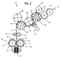
- an interfolding machine 25 is operable to convert a web of material 30 into a stack of interfolded sheets of material shown at 32.
- Interfolding machine 25 includes folding rolls incorporating the tucker assembly of the present invention, and generally includes a first pull roll 35 and a second pull roll 40 that receive the web of material 30 along a path (illustrated by an arrow 42 in FIG. 2) from a supply roll (not shown) into the interfolding machine 20.
- the first and second pull rolls 35 and 40 define a nip through which the web of material 30 passes, and function to unwind the web of material 30 and feed the web of material 30 in a path (illustrated by an arrow 44 in FIG.
- the knife roll 50 cuts the web of material 30 into sheets, each of which has a predetermined length, and the bed roll 45 carries the sheets of material along a path (illustrated by arrow 52 in FIG. 2) toward and through a nip defined between bed roll 45 and a retard roll 55, which rotates at a slower speed of rotation than the bed roll 45.
- the retard roll 55 cooperates with a nip roller assembly 60 (FIG. 2) to form an overlap between the consecutive sheets of material.
- the retard roll 55 carries the overlapped sheets of material along a path (illustrated by arrow 68 in FIG. 2) to a lap roll 65.
- the lap roll 65 works in combination with a count roll 75 to eliminate the overlap between adjacent sheets of material at a predetermined sheet count, so as to create a separation in the stack 32 of interfolded sheets discharged from the interfolding machine 25.
- the lap roll 65 carries the overlapped sheets of sheet 30 along a path (illustrated by arrow 78 in FIG. 2) toward a nip defined between a first assist roll 80 and an adjacent second assist roll 85.
- the first and second assist rolls 80 and 85 feed the sheets of the material to a nip defined between a first folding roll 90 and a second folding roll 95.
- the first and second folding rolls 90 and 95 generally rotate in opposite directions (illustrated by arrows 96 and 98, respectively, in FIG. 2) to receive the overlapped sheets of material 30 therebetween.
- the periphery of the first folding roll 90 generally includes a series of the tucker assemblies 20 in accordance with the invention, and a series of gripper assemblies 100 uniformly and alternately spaced to interact with a series of tucker assemblies 20 and gripper assemblies 100 of the adjacent second folding roll 95.
- the series of alternately spaced tucker assemblies 20 and gripper assemblies 100 of the first and second folding rolls 90 and 95 interact to grip, carry, and release the sheets of material in a desired manner so as to form the desired interfolded relationship in the sheets of material and to form stack 32 of interfolded sheets.
- the folding rolls 90 and 95 may be driven by a drive system 110 having a drive belt assembly 115 (FIG. 1).
- the stack 32 of interfolded sheets is discharged from between the first and second folding rolls 90 and 95 in a generally vertically-aligned fashion.
- the stack 32 of interfolded sheets may be supplied to a discharge and transfer system (not shown), which guides and conveys the stack 32 from the generally vertically-aligned orientation at the discharge of the interfolding machine 25 to a generally horizontally-aligned movement.
- a discharge and transfer system is described in U.S. Patent No. 6,712,746 entitled “Discharge and Transfer System for Interfolded Sheets," filed May 5, 2000, the disclosure of which is hereby incorporated herein by reference in its entirety.
- each of the gripper assemblies 20 is generally located at a distance from the next adjacent tucker assembly 100 along a circumference of each of the first and second folding rolls 90 and 95.
- the spacing between the gripper assemblies 100 and the tucker assemblies 20 determines the longitudinal dimension or length between the folds in the sheets of sheet 30 as measured in a direction of travel (illustrated by arrows 96 and 98) of the first and second folding rolls 90 and 95.
- FIGS. 3 illustrates a detailed cross-sectional view of folding rolls 90 and 95, showing one of the series of tucker assemblies 20 in accordance with the present invention, and which is mounted to folding roll 95, interacting with one of the series of gripper assemblies 100 of folding roll 90.
- the other alternating series of gripper assemblies 100 and tucker assemblies 20 of both the first and second folding rolls 90 and 95 are constructed similarly and interact in a similar manner.
- the tucker assembly 20 generally extends in a radial outward direction from the outer circumference of the folding roll 95 to engage the gripper assembly 100 that is generally positioned in a recessed location on the folding roll 90.
- the tucker assembly 20 is configured to tuck the sheet 30 between a blade 116 and an anvil 118 of the gripper assembly 100, when the gripper assembly 100 is in an open position.
- the blade 116 of the gripper assembly 100 subsequently rotates in a timed manner to grip the tucked sheet 30 against anvil 118 as the tucker assembly 20 is moved out of engagement with the sheet 30.
- the gripper assembly 100 In the closed position, the gripper assembly 100 carries and then releases the sheet 30 so as to create the folds in the sheets 30 that are formed in interfolded stack 32.
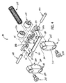
- FIGS. 3-5 show one embodiment of the tucker assembly 20 in accordance with the present invention.
- tucker assembly 20 has a sectioned tucker element 125, a first and a second tucker cap 130 and 132, respectively, a first and a second roller 134 and 136, respectively, a first and a second pin 140 and 142, respectively, and a spring 155 disposed in a cavity or slot 160 in the folding roll 95. It is understood that others in the series of tucker assemblies 20 of the first and second folding rolls 90 and 95 are constructed in similar manner.
- the spring 155 generally biases the tucker element 125 in a radially outward direction (illustrated by arrow 16) with respect to the outer periphery or circumference 165 of the folding roll 95.
- FIGS. 6-8 show the tucker element 125 of FIGS. 3-5 in detail.
- the tucker element 125 includes a pointed end 180, a midsection 185, and a base portion 190.
- the pointed end 180 is configured to engage the gripper assembly 100 of the adjacent folding roll 90 (FIG. 3).
- the base portion 190 of the tucker element 125 includes a recess or opening 195 to receive the outer end of the spring 155.
- First and second transverse pin openings or passages 200a and 200b, respectively, extend along an axial length of the tucker element 125 and are configured to receive the pins 140 and 142, respectively.
- a pair of inner recesses 215a and 215b extend outwardly from the inner surface of the base portion 190 of the tucker element 125, and are configured to receive the rollers 134 and 136, respectively.
- the number of recesses 215a and 215b and respective rollers 134 and 136 can vary.
- An outer recess 220 extends inwardly from the pointed end 180.
- Another pair of openings 225a and 225b pass through the midsection 185. The openings 225a and 225b receive fasteners (not shown) to hold the pins 140 and 142 in position on the tucker element 125.
- the tucker caps 130 and 132 are generally disposed between adjacent tucker elements 125 (See FIG. 3) in a manner so as to restrain the pins 140 and 142 and the tucker element 125 against the bias of the spring 155.
- the tucker caps 130 and 132 generally include respective outer faces 230 and 232 and respective inner faces 235 and 236.
- the outer faces 230 and 232 are generally arcuate-shaped, and match an arcuate shape of an inner surface 240 defined by an outer wall section 245 of the folding roll 95 (See FIG. 3).
- the inner faces 235 and 236 are generally configured to interface with the base portion 190 of the tucker element 125 and with an inner surface 250 of the folding roll 95 (See FIG. 3).
- the inner faces 235 and 236 further include slot portions 255 and 256, respectively, which retain at least a portion of the pins 140 and 142, respectively, against base portion 190 of the tucker element 125.
- the pins 140 and 142 are engaged within the openings or passages 200a and 200b, respectively, in the tucker element 125.
- the pins 140 and 142 extend into aligned axial passages in rollers 134, 136, respectively, and define inner portions that are received within aligned passages in rollers 134, 136, respectively, to support the tucker 125 on the rollers 134 and 136, respectively.
- the pins 140 and 142 extend axially outwardly from the tucker element 125, and are received between the slot portions 255 and 256 of the caps 130 and 132 and outwardly facing troughs formed in the base portion 190 of the tucker element 125.
- the pins 140 and 142 and mounted rollers 134 and 136, respectively, provide rotational location and guidance for inward and outward movement of the tucker element 125 along facing walls or surfaces 265 defining the cavity or slot 160 (FIG. 3).
- Folding roll 95 also defines a central axial passage AP which is supplied with pressurized air from a suitable pressurized air source, and which communicates with radial passages RP formed in folding roll 95that supply pressurized air to cavity or slot 160 inwardly of tucker element 120 and caps 130, 132. This feature functions to expel air under pressure around the components of tucker assembly 20.
- FIGS. 9-14 generally illustrate the sequence of operation of the tucker assembly 20.
- the tucker assembly 20 is generally held in a radially aligned position in the slot 160 by the pins 140 and 142 in combination with the caps 130 and 132 (FIGS. 4 and 5) by application of an outward biasing force applied by the spring 155.
- pointed end 180 of tucker element 125 contacts sheet 30 so as to create a fold or crease in sheet 30.
- Tucker element 125 then interacts with the gripper assembly 100 of the adjacent roller 90 as illustrated in FIG. 10, so as to position the fold or crease in sheet 30 against the anvil of the gripper assembly 100 while the blade 116 of gripper assembly 100 is maintained in the open position.
- the spring 155 forces the tucker element 125 outwardly, and maintains tucker element 125 in a radially aligned position.
- Blade 116 of gripper assembly 100 is then moved to the closed position as shown in FIG. 11, so that blade 116 engages the sheet 30 within the recess 220 defined by tucker element 125, to clamp the fold in sheet 30 against the anvil 118.
- FIGS. 12 and 13 illustrate that, as the adjacent folding rolls 90 and 95 continue to rotate, the tucker element 125 pivots (illustrated by arrow 278) and retracts (illustrated by arrow 280) upon disengagement with gripper assembly 100.
- the blade 116 of the gripper assembly 100 engages against the sheet 30 and the anvil 118, limiting bounce as the gripper assembly 100 carries the sheet 30.
- the bias of the spring 155 and the interaction of the base portion 190 and the pins 140 and 142 against the caps 130 and 132 functions in combination to re-center the tucker element 125 in a generally radially aligned position in the slot 160.
- the tucker element 125 is operable to retract against the bias of the spring 155 in a radially inward direction (illustrated by arrow 280 in FIG. 13) along the slot 160.
- the pins 140 and 142 are moved inwardly out of contact with the cap slot portions 255, 256.
- rollers 134 and 136 roll inwardly along the surfaces 265 of slot 160, against the outward biasing force of spring 155, until the pointed end 180 of tucker element 125 is moved out of contact with the outer surface 285 or the anvil of gripper assembly 100. Rollers 134, 136 function to maintain base 190 of tucker element 125 and pins 140 and 142 in a centered position in the slot 160. Thereafter, spring 155 functions to move tucker element 125 outwardly to seat pins 140 and 142 in engagement with cap slot portions 255, 256, respectively. As explained previously, spring 155 then operates to return tucker element 125 to a radially aligned position within cavity or slot 160. This feature enables tucker assembly to accommodate slight misalignment between tucker assembly 20 and gripper assembly 100, and reduces the potential costly and undesirable jams that may otherwise occur during operation of the interfolding machine 25.
- FIGS. 15 and 16 show another embodiment of a tucker assembly in accordance with the present invention.
- the tucker assembly is shown at 300, and is mounted on adjacent folding rolls 305 and 310 that have a similar construction and operation as folding rolls 90 and 95 as shown and described previously, including alternately spaced tucker assemblies 300 and gripper assemblies 312 that are constructed similarly to gripper assemblies 100 described above.
- Tucker assembly 300 is generally mounted in a slot 314 (FIGS. 20-22) in the folding roll 310. It is understood that the tucker assemblies 300 of the adjacent folding roll 305 are constructed in a similar manner. Tucker assembly 300 generally includes a tucker element 315 that cooperates with gripper assemblies 312 in a similar manner as tucker element 125 as gripper assemblies 100, described previously, to form a crease or fold in a sheet of material, shown at 450.
- Tucker assembly 399 further includes a first tucker cap 320 and a second tucker cap 322, a first pin 325 and a second pin 326, a first slot spring 330 and a second slot spring 332, a bumper 335, a first cartridge 340 and a second cartridge 342, and a pivot spring 345.
- the first cartridge 340 and the first pivot spring 330 are positioned to interface with the tucker cap 320, and the second cartridge 342 and the second pivot spring 332 are positioned to interface with tucker cap 322.
- the tucker element 315, the first and second pins 325 and 326, and the first and second cartridges 340 and 342 are installed in the slot 314 and retained against the bias of the first and second slot springs 330 and 332 by the tucker caps 320 and 322.
- tucker element 315 includes a pointed end 355, a midsection 360, and a base portion 365.
- the pointed end 355 of the tucker element 315 is configured to interface with the gripper assembly 312.
- Tucker element 315 includes a first recess 370 that extends inwardly from pointed end 355.
- a first opening or passage 375a and a second opening or passage 375b extend axially inwardly from the opposite ends of tucker 310, and receive inner portions of the pins 325 and 326, respectively.
- the outer end portions of pins 325, 326 extend outwardly of the ends of base portion 365.
- the tucker element 315 further includes a recess 380 in one of the faces 385 of the midsection 360 to receive the pivot spring 345, and another recess 390 in an opposite face 395 of the midsection 360 to receive the bumper 335.
- the location of the pivot spring 345 and bumper 335 and their respective recesses 380 and 390 can vary.
- the bias of the pivot spring 345 against the bumper 335 is operable to radially align the tucker element 315 in the center of the slot 314.
- the bumper 335 and the pivot spring 330 also act to minimize bounce in the tucker element 315.
- the tucker caps 320 and 322 function to retain the tucker element 315 in the slot 314.
- Tucker caps 320 and 322 engage the outer ends of base portion 365, and include inner faces 395 and 396 and an outer faces 400 and 402, respectively.
- the inner faces 395 and 396 are configured to interface with the ends of base portion 365 of the tucker element 315 and an inner surface 405 of the roll 310.
- the outer faces 400 and 402 of the cap 320 are configured with an arcuate shape that matches an arcuate outer surface 410 of the roll 310.
- the caps 320 and 322 are secured to the roll 310 with one or more fasteners 420.
- the type and number of fasteners 420 can vary.
- pins 325 and 326 are forced against the respective caps 320 and 322 by the slot springs 330 and 332 and cartridges 340 and 342, respectively.
- the outer end portions of pins 325 and 326 protrude in an axial outward direction from the tucker element 315 and engage respective slot portions 424 and 426 defined by the caps 320 and 322, respectively. With this arrangement, the tucker element 315 pivots about a pivot axis defined by the pins 325 and 326.
- pins 325 and 326 occupy approximately half the full length of slot portions 424 and 426 defined by respective caps 320 and 322, and a pin of an adjacent tucker element takes up the remaining portion of the length of slot portions 424 and 426, respectively, to pivotably mount the adjacent tucker element in the same manner.
- the length and size of the pins 325 and 326 can vary.
- the cartridges 340 and 342 are centrally located within the slot 314.
- the cartridges 340 and 342 each are generally cylindrical structures having respective top surfaces 428 and 429 that define respective slots 432 and 433 to receive the pins 325 and 326, respectively.
- the cartridges 340 and 342 and respective slot springs 330 and 332 bias the tucker element 315 in a radial outward direction with respect to a circumference 434 of the folding roll 310.
- the caps 320 and 322 retain the tucker element 315 in the slot 314 against the bias of the cartridges 340 and 342 and respective slot springs 330 and 332.
- the tucker element 315 further includes a pair of openings 435a and 435b that extend through the midsection 360 and above the base portion 365.
- the openings 435a and 435b receive fasteners (not shown) to hold the pins 326 and 326 in position on the tucker element 315.
- the tucker element 315 interfaces with the gripper assembly 312 of the adjacent roll 305.
- the pointed end 355 of tucker element 315 engages a sheet 450, and moves the sheet 450 into contact with the anvil 442 of the adjacent gripper assembly 312.
- the contact of the tucker element 315 against the anvil 442 forces the tucker element 315 to pivot slightly forward against the bumper 335.
- the tucker element 315 moves in the opposite direction against the force of pivot spring 345.
- the blade 440 of the adjacent gripper assembly 312 is moved against the anvil 442 to grip the sheet 450.
- the tucker element 315 retracts is retracted within slot 314 against the biasing force of springs 330 and 332, which facilitates disengagement of tucker element 314 from anvil 442 and sheet 450.
- the blade 440 clamps the sheet 450 against the anvil 442, and the pivoting and retracting movement of tucker element 315 functions to eliminate bounce that may otherwise occur in the folding process.
- the pivot spring 345 in combination with the bumper 335 then return the tucker element 315 to a centered position in the slot 314, and springs 330 and 332 return tucker element 315 to its fully extended position.
- tucker element 315 retracts within slot 314 against the outward bias of springs 330 and 332.
- Tucker element 315 and attached pins 325 and 326 retract in a radial inward direction within the slot 314. As the tucker element 315 and attached pins 325 and 326 retract inwardly, the pins 325 and 326 are moved out of engagement with the caps 320 and 322, and move inwardly against the bias of slot springs 330 and 332 along with cartridges 340 and 342, respectively.
- the retraction of the tucker element 315 along the slot 314 prevents the tucker element 315 from damaging the adjacent roll 305 and its associated components, and also prevents jams which may otherwise occur, in the event the of a disruption in the timing of the rolls and or deviations due to manufacturing or installation tolerances.
- the bias of the cartridges 340 and 342 and associated slot springs 330 and 332 along with the pivot spring 345 and bumper 335 act to return tucker element 315 to the extended position, and to self center the tucker element 315 in the slot 314.
- the present invention contemplates any type of arrangement that provides pivoting movement of the tucker element relative to the folding roll, and is not limited to a pin-type pivot arrangement.
- pivoting movement of the tucker element within the slot may be accomplished without a pivot pin by means of the base of the tucker engaging the slot edges, with the tapered area of the base accommodating pivoting movement of the tucker element.
- the present invention contemplates that the tucker element is at a predetermined orientation relative to the folding roll when the tucker element is in the extended position.
- the predetermined orientation may be radially aligned, it is also understood that the predetermined orientation may also be angled or biased either forwardly or rearwardly within the slot.
- tucker assembly 20, 300 in accordance with the invention has been generally described with reference to an interfolding machine 25 for folding sheets 30 into an interfolded stack 32, the application of the tucker assembly 20, 300 is not so limited.
- the tucker assembly of the invention could be employed to fold any type of sheet or web material such as 30, for a wide variety of uses to machines and is not limiting on the invention.
Landscapes
- Folding Of Thin Sheet-Like Materials, Special Discharging Devices, And Others (AREA)
Claims (17)
- Faltwalzenbaugruppe, die so konfiguriert ist, dass sie mit einer Greiferbaugruppe einer daneben liegenden, rotierenden Walze (95) zusammenwirkt und eine Materialbahn faltet, wobei die Faltwalzenbaugruppe Folgendes umfasst:eine rotierende Walze (90) mit einem darin ausgebildeten Schlitz (160), in dem eine Faltbaugruppe (20) angebracht ist,wobei die Faltbaugruppe (20) Folgendes umfasst:ein Faltelement (125), das in dem Schlitz (160) angeordnet ist,eine Feder (155), die in dem Schlitz (160) hinter dem Faltelement (125) angeordnet ist, wobei die Feder (155) das Faltelement (125) nach außen hin vorspannt,eine Haltevorrichtung (130, 132), die so konfiguriert ist, dass sie das Faltelement (125) in dem Schlitz (160) gegen die Vorspannung der Feder (155) hält, wobei das Faltelement (125) gegen die Vorspannung der Feder (155) in den Schlitz (160) eingefahren werden kann, dadurch gekennzeichnet, dasseine Schwenkvorrichtung (134, 136, 140, 142) zwischen der Walze (90) und dem Faltelement (125) angeordnet ist, mit der das Faltelement (125) schwenkbar an der Walze angebracht wird und sich um eine Schwenkachse herum bewegen kann.
- Faltwalzenbaugruppe nach Anspruch 1, bei der die Haltevorrichtung eine Kappe (130, 132) umfasst, die in eine Auflagefläche greift, die von der rotierenden Walze (90) definiert wird.
- Faltwalzenbaugruppe nach Anspruch 1 oder Anspruch 2, bei der die Schwenkvorrichtung einen Zapfen (140, 142) aufweist, der von dem Faltelement (125) aus nach außen hin verläuft, wobei der Zapfen (140, 142) von der Feder (155) gegen die Haltevorrichtung (130, 132) vorgespannt wird.
- Faltwalzenbaugruppe nach Anspruch 3, bei der die Haltevorrichtung eine Kappe (130, 132) umfasst, die einen Schlitzteil (255, 256) aufweist, der den Zapfen (140, 142) aufnehmen kann.
- Faltwalzenbaugruppe nach einem der vorhergehenden Ansprüche, bei der das Faltelement (125) einen Fußteil (190) aufweist, der einem spitz zulaufenden Ende (180) gegenüberliegt, und der Fußteil (190) eine Aussparung (195) aufweist, die die Feder (155) aufnehmen kann.
- Faltwalzenbaugruppe nach Anspruch 5, bei der die Schwenkvorrichtung einen Zapfen (140, 142) aufweist, der von dem Faltelement (125) aus nach außen hin verläuft, und zumindest ein Teil des Zapfens (140, 142) zwischen einem Schlitz in dem Fußteil (190) des Faltelements und einem Schlitzteil (255, 256) in der Kappe, die von der Haltevorrichtung definiert wird, aufgenommen wird.
- Faltwalzenbaugruppe nach einem der vorhergehenden Ansprüche, die des Weiteren eine Walze (134, 136) umfasst, die in den Schlitz (160) greift, wobei die Walze (134, 136) die Bewegung des Faltelements (125) in dem Schlitz (160) führt und das Faltelement (125) schwenkbar an der Walze (134, 136) angebracht ist.
- Faltwalzenbaugruppe nach Anspruch 7, bei der die Schwenkvorrichtung ein Paar nach außen hin verlaufende Zapfen (140, 142) aufweist, die von dem Faltelement (125) aus in entgegengesetzter Richtung nach außen hin verlaufen, und die Zapfen (140, 142) in von dem Faltelement (125) definierten Durchgängen (200a, 200b) aufgenommen werden und das Faltelement (125) eine erste und eine zweite Aussparung (215a, 215b) aufweist, in denen sich die erste und die zweite Walze (134, 136) befinden, und jeder Zapfen (140, 142) in eine der Walzen (134, 136) greift und für eine Schwenkbewegung des Faltelements (125) in Bezug zu den Walzen (134, 136) sorgt.
- Faltwalzenbaugruppe nach Anspruch 1, bei der die Schwenkvorrichtung einen oder mehrere Zapfen (140, 142) umfasst, die in das Faltelement (125) eingreifen, und jeder Zapfen (140, 142) einen äußeren Teil aufweist, der von dem Faltelement (125) aus in axialer Richtung allgemein nach außen hin verläuft.
- Faltwalzenbaugruppe nach Anspruch 1, bei der das Faltelement (126) einen Fußteil (190), der einem spitz zulaufenden Ende (180) gegenüberliegt, sowie einen Mittelteil (185) dazwischen und der Mittelteil (185) eine Aussparung (225a) aufweist, die die Feder (155) aufnehmen kann.
- Faltmaschine für das Falten einer Materialbahn, die Folgendes umfasst :eine erste Faltwalzenbaugruppe nach einem der vorhergehenden Ansprüche undeine zweite Faltwalzenbaugruppe nach einem der vorhergehenden Ansprüche,wobei die rotierende Walze (90, 95) jeder Faltwalzenbaugruppe mehrere Faltbaugruppen (20) aufweist, die um ihren Umfang herum mit mehreren Greiferbaugruppen (100) abwechselnd in einem Abstand angeordnet verteilt sind, wobei jede Greiferbaugruppe (100) der ersten oder der zweiten Faltwalzenbaugruppe so positioniert ist, dass sie mit einer Faltbaugruppe (20) der jeweils anderen, d. h. der zweiten oder der ersten Faltwalzenbaugruppe zusammenwirkt und eine Materialbahn dazwischen faltet.
- Faltmaschine nach Anspruch 11, bei der die Schwenkvorrichtung ein Paar ausgerichteter Gelenkzapfen aufweist, die von dem Faltelement aus in entgegengesetzter Richtung nach außen hin verlaufen.
- Faltmaschine nach Anspruch 12, bei der ein erster Teil eines ersten Zapfens in einem von dem Faltelement definierten ersten Durchgang aufgenommen wird und sich ein zweiter Teil des ersten Zapfens in einem Durchgang eines daneben liegenden Faltelements befindet.
- Verfahren für das Zusammenwirken einer Faltbaugruppe einer Faltwalze mit einer Greiferbaugruppe, die an einer daneben liegenden Faltwalze angebracht ist, wobei sich eine Materialbahn dazwischen befindet, das folgende Schritte umfasst:Bereitstellen einer Faltwalzenbaugruppe nach einem der Ansprüche 1 bis 10,Ausrichten einer Faltbaugruppe (20) der Faltwalzenbaugruppe neben einer Greiferbaugruppe (100) der daneben liegenden Faltwalze (95),Drehen der Faltwalzenbaugruppe und der daneben liegenden Walze, so dass das Faltelement (20) der Faltwalzenbaugruppe mit der Greiferbaugruppe (100) der daneben liegenden Walze (95) gekoppelt ist,Drücken des Faltelements (125) gegen die Greiferbaugruppe, so dass es in die Materialbahn greift, undSchwenken des Faltelements (125) um eine Schwenkvorrichtung der Faltbaugruppe (20).
- Verfahren nach Anspruch 14, das des Weiteren den Schritt aufweist, dass das Faltelement seiner radial nach außen gerichteten Vorspannung entgegen in den Schlitz eingefahren wird.
- Verfahren nach Anspruch 14 oder Anspruch 15, das des Weiteren den Schritt aufweist, dass das Faltelement in dem Schlitz um die Schwenkvorrichtung herum zentriert wird.
- Verfahren nach einem der Ansprüche 14 bis 16, das des Weiteren den Schritt umfasst, dass das Faltelement in dem Schlitz an einer Walze gegen eine Fläche, die den Schlitz definiert, radial nach innen oder radial nach außen bewegt wird, und bei dem der Schritt, in dem das Faltelement geschwenkt wird, dadurch ausgeführt wird, dass das Faltelement an der Walze geschwenkt wird.
Applications Claiming Priority (6)
| Application Number | Priority Date | Filing Date | Title |
|---|---|---|---|
| US953176 | 1992-09-29 | ||
| US50740503P | 2003-09-30 | 2003-09-30 | |
| US50740303P | 2003-09-30 | 2003-09-30 | |
| US507405P | 2003-09-30 | ||
| US507403P | 2003-09-30 | ||
| US10/953,176 US7771337B2 (en) | 2003-09-30 | 2004-09-29 | Self-centering tucker assembly for a folding roll |
Publications (2)
| Publication Number | Publication Date |
|---|---|
| EP1520819A1 EP1520819A1 (de) | 2005-04-06 |
| EP1520819B1 true EP1520819B1 (de) | 2007-06-13 |
Family
ID=34317505
Family Applications (1)
| Application Number | Title | Priority Date | Filing Date |
|---|---|---|---|
| EP04256074A Expired - Lifetime EP1520819B1 (de) | 2003-09-30 | 2004-09-30 | Verfahren und Vorrichtung für ein selbstzentrierendes Falzschwert eines Falzzylinders |
Country Status (5)
| Country | Link |
|---|---|
| US (1) | US7771337B2 (de) |
| EP (1) | EP1520819B1 (de) |
| AT (1) | ATE364570T1 (de) |
| DE (1) | DE602004006932T2 (de) |
| ES (1) | ES2287657T3 (de) |
Families Citing this family (10)
| Publication number | Priority date | Publication date | Assignee | Title |
|---|---|---|---|---|
| ITMI20060961A1 (it) * | 2006-05-16 | 2007-11-17 | Omet Srl | Dispositivo perfezionato per la piegatura di materiale flessibile |
| US20100261594A1 (en) | 2009-04-08 | 2010-10-14 | C.G. Bretting Manufacturing Co., Inc. | Resilient tucker element for interfolder folding rolls |
| EP2593063B1 (de) * | 2010-07-15 | 2014-05-21 | The Procter and Gamble Company | Vorrichtung und verfahren zum falten von artikeln |
| US20130184139A1 (en) * | 2012-01-13 | 2013-07-18 | C.G. Bretting Manufacturing Co., Inc. | Freely movable tucker apparatus and method |
| US9371209B2 (en) | 2012-05-01 | 2016-06-21 | C.G. Bretting Manufacturing Co., Inc. | Single path single web single-fold interfolder and methods |
| US10449746B2 (en) | 2016-06-27 | 2019-10-22 | C. G. Bretting Manufacturing Co., Inc. | Web processing system with multiple folding arrangements fed by a single web handling arrangement |
| IT202100010283A1 (it) | 2021-04-22 | 2022-10-22 | Koerber Tissue Fold S R L | Unita’ di piega, o interfogliatura, di fogli di carta in una macchina per la trasformazione della carta |
| IT202100011531A1 (it) | 2021-05-06 | 2022-11-06 | Koerber Tissue Fold S R L | Unita’ di piega, o interfogliatura, di fogli di carta in una macchina per la trasformazione della carta |
| IT202100012539A1 (it) | 2021-05-14 | 2022-11-14 | Koerber Tissue Fold S R L | Macchina per la produzione di prodotti laminari in materiale cartaceo, in particolare pacchi di tovaglioli, fazzoletti, o simili prodotti e relativo metodo di produzione |
| IT202300021915A1 (it) | 2023-10-20 | 2025-04-20 | Valmet Tissue Converting S R L | Macchina per la trasformazione della carta e prodotto di fogli piegati o interfogliati ottenibile con tale macchina |
Family Cites Families (31)
| Publication number | Priority date | Publication date | Assignee | Title |
|---|---|---|---|---|
| US3124349A (en) | 1964-03-10 | huffman | ||
| DE136593C (de) | ||||
| US1595992A (en) | 1925-12-05 | 1926-08-17 | William H Cannard | Interfolding machine |
| US2092952A (en) | 1934-11-26 | 1937-09-14 | Samuel J Campbell | Paper interfolding machine |
| US3214162A (en) | 1963-11-15 | 1965-10-26 | Standard Register Co | Gripper support means for rotary folding apparatus |
| US3640522A (en) | 1970-03-12 | 1972-02-08 | Johnson & Johnson | Sheet folding apparatus |
| SU441773A1 (ru) | 1973-07-12 | 1976-05-25 | Типография Издательства "Известия" | Фальцаппарат ударного типа газетных ротационных печатных машин |
| US4095780A (en) * | 1976-10-07 | 1978-06-20 | Harris Corporation | Retracting tucker blade and brush for cylinder folder |
| US4073485A (en) * | 1977-01-10 | 1978-02-14 | Gregg Engineering Corporation | Apparatus for making multiple page printed booklets |
| DD136593A1 (de) * | 1978-05-25 | 1979-07-18 | Oskar Birke | Falzmesserzylinder |
| FR2432465A1 (fr) | 1978-08-01 | 1980-02-29 | Marinoni | Perfectionnement aux machines de pliage rotatives |
| US4270744A (en) * | 1979-06-15 | 1981-06-02 | C. G. Bretting Mfg. Co. Inc. | Tuckers on mechanical folding rolls |
| US4494949A (en) * | 1983-01-10 | 1985-01-22 | The Lehigh Press, Inc. | Sheet folding apparatus and method |
| US4493690A (en) * | 1983-01-20 | 1985-01-15 | Rockwell International Corporation | Cam activated anti-dog-ear device |
| US4519596A (en) | 1984-07-13 | 1985-05-28 | Paper Converting Machine Company | Method and apparatus for folding diapers with selective movement of orbit of tucker balde |
| US4765604A (en) | 1987-04-17 | 1988-08-23 | C. G. Bretting Manufacturing Company | Resilient creaser |
| US4917665A (en) | 1987-06-16 | 1990-04-17 | C. G. Bretting Manufacturing Co. Inc. | Bedroll interfolding machinery improvement |
| US4778441A (en) | 1987-06-16 | 1988-10-18 | C.G. Bretting Manufacturing Co., Inc. | Interfolding machinery improvement |
| US4822328A (en) | 1987-12-21 | 1989-04-18 | Paper Converting Machine Company | Folding apparatus and method |
| DE3923436A1 (de) | 1989-07-15 | 1991-01-24 | Winkler Duennebier Kg Masch | Verfahren und vorrichtung zum herstellen von papierstapeln |
| DE3927422C2 (de) | 1989-08-19 | 1998-07-09 | Winkler Duennebier Kg Masch | Verfahren und Vorrichtung zur Herstellung von zahlgerechten Teilstapeln aus überlappend ineinandergefalteten Tüchern |
| US4976673A (en) * | 1989-09-22 | 1990-12-11 | Dow Brands Inc. | Apparatus and method for the production of flexible bags |
| US5609557A (en) * | 1994-05-19 | 1997-03-11 | Te; Tan Y. | Paper pallet with an immproved configuration |
| US5522586A (en) | 1994-09-07 | 1996-06-04 | Rockwell International Corporation | Folding apparatus with multiple speed folding jaw cylinder |
| FR2726259B1 (fr) | 1994-10-27 | 1997-01-17 | Heidelberg Harris Sa | Dispositif de changement de mode d'un cylindre d'accumulation d'une plieuse |
| IT1278193B1 (it) * | 1995-05-10 | 1997-11-17 | Azionaria Costruzioni Acma Spa | Metodo ed unita' per la saldatura longitudinale di involucri tubolari |
| ATE201008T1 (de) * | 1995-10-31 | 2001-05-15 | Windmoeller & Hoelscher | Vorrichtung zum übergeben von zetteln von einem rotierend angetriebenen ersten zylinder an einen rotierend angetriebenen zweiten zylinder |
| AU3196699A (en) | 1998-03-20 | 1999-10-11 | Specialty Systems Advanced Machinery, Inc. | High speed paper folding machine |
| US20030125180A1 (en) | 2001-12-27 | 2003-07-03 | Sosalla Gerald K. | Apparatus and method for folding products |
| US6837841B2 (en) * | 2002-09-30 | 2005-01-04 | Hewlett-Packard Development Company, L.P. | Method and apparatus for sheet folding |
| US6942610B2 (en) * | 2003-05-28 | 2005-09-13 | Specialty Systems Advanced Machinery, Inc. | Web folding machine |
-
2004
- 2004-09-29 US US10/953,176 patent/US7771337B2/en not_active Expired - Fee Related
- 2004-09-30 EP EP04256074A patent/EP1520819B1/de not_active Expired - Lifetime
- 2004-09-30 AT AT04256074T patent/ATE364570T1/de not_active IP Right Cessation
- 2004-09-30 ES ES04256074T patent/ES2287657T3/es not_active Expired - Lifetime
- 2004-09-30 DE DE602004006932T patent/DE602004006932T2/de not_active Expired - Lifetime
Also Published As
| Publication number | Publication date |
|---|---|
| US20050070417A1 (en) | 2005-03-31 |
| EP1520819A1 (de) | 2005-04-06 |
| US7771337B2 (en) | 2010-08-10 |
| ES2287657T3 (es) | 2007-12-16 |
| ATE364570T1 (de) | 2007-07-15 |
| DE602004006932T2 (de) | 2008-02-14 |
| DE602004006932D1 (de) | 2007-07-26 |
Similar Documents
| Publication | Publication Date | Title |
|---|---|---|
| EP1520819B1 (de) | Verfahren und Vorrichtung für ein selbstzentrierendes Falzschwert eines Falzzylinders | |
| JP3361817B2 (ja) | くわえを調節するための装置 | |
| US3489406A (en) | Folding apparatus | |
| EP1520822B1 (de) | Verfahren und Vorrichtung für das Überlappung von Bogen | |
| EP3067303B1 (de) | Vorrichtung und verfahren zur herstellung von bogen unterschiedlicher längen oder bogen mit unterschiedlichen plattenlängen, und bearbeitungswalze für handhabung von blätter | |
| US6159138A (en) | Folder having a cylinder with retractable grippers and a cooperating cylinder with retractable copy guiding devices | |
| US5365843A (en) | Printing press with web breaking assembly | |
| CA2483172C (en) | Self-centering tucker assembly for a folding roll | |
| EP0322186B1 (de) | Apparat und Verfahren zum Falzen | |
| JP3983547B2 (ja) | 折り装置 | |
| EP1520818A1 (de) | Vorrichtung und Verfahren zum Verstellen der Phase von Falzwalzen | |
| EP1520821A1 (de) | Vorrichtung und Verfahren zur Schmutzvermeidung um ein Schwert einer Falzmaschine | |
| EP1277686B1 (de) | Schneid- und Faltmechanismus für eine Rollenrotationsdruckmaschine | |
| EP1209112B1 (de) | Führungseinrichtung für einen Falzapparat | |
| JP2000351194A (ja) | 輪転印刷機の折り装置用の胴部材 | |
| US6881181B2 (en) | Sheet folding apparatus | |
| US6923752B1 (en) | Folding cylinder with expansion segment | |
| CA2026240A1 (en) | Paper jam protected folding apparatus | |
| EP1520823B1 (de) | Ventilsystem für die Zählrolle einer Ineinanderfaltmaschine | |
| JP3741679B2 (ja) | シート折り用ローラ | |
| JPH0647427B2 (ja) | 折機の折紙用部材切替装置 | |
| US20130184139A1 (en) | Freely movable tucker apparatus and method | |
| JP2020138832A (ja) | シート処理装置及び画像形成システム | |
| CA2483175C (en) | Method of and assembly for lapping consecutive sheets of web material | |
| EP4011813B1 (de) | Bogenstapler mit einer bogenwendevorrichtung und einer stützvorrichtung |
Legal Events
| Date | Code | Title | Description |
|---|---|---|---|
| PUAI | Public reference made under article 153(3) epc to a published international application that has entered the european phase |
Free format text: ORIGINAL CODE: 0009012 |
|
| AK | Designated contracting states |
Kind code of ref document: A1 Designated state(s): AT BE BG CH CY CZ DE DK EE ES FI FR GB GR HU IE IT LI LU MC NL PL PT RO SE SI SK TR |
|
| AX | Request for extension of the european patent |
Extension state: AL HR LT LV MK |
|
| 17P | Request for examination filed |
Effective date: 20051003 |
|
| AKX | Designation fees paid |
Designated state(s): AT BE BG CH CY CZ DE DK EE ES FI FR GB GR HU IE IT LI LU MC NL PL PT RO SE SI SK TR |
|
| GRAP | Despatch of communication of intention to grant a patent |
Free format text: ORIGINAL CODE: EPIDOSNIGR1 |
|
| RTI1 | Title (correction) |
Free format text: METHOD AND ASSEMBLY FOR A SELF CENTERING TUCKER ON A FOLDING ROLL |
|
| GRAS | Grant fee paid |
Free format text: ORIGINAL CODE: EPIDOSNIGR3 |
|
| GRAA | (expected) grant |
Free format text: ORIGINAL CODE: 0009210 |
|
| AK | Designated contracting states |
Kind code of ref document: B1 Designated state(s): AT BE BG CH CY CZ DE DK EE ES FI FR GB GR HU IE IT LI LU MC NL PL PT RO SE SI SK TR |
|
| PG25 | Lapsed in a contracting state [announced via postgrant information from national office to epo] |
Ref country code: CH Free format text: LAPSE BECAUSE OF FAILURE TO SUBMIT A TRANSLATION OF THE DESCRIPTION OR TO PAY THE FEE WITHIN THE PRESCRIBED TIME-LIMIT Effective date: 20070613 Ref country code: LI Free format text: LAPSE BECAUSE OF FAILURE TO SUBMIT A TRANSLATION OF THE DESCRIPTION OR TO PAY THE FEE WITHIN THE PRESCRIBED TIME-LIMIT Effective date: 20070613 |
|
| REG | Reference to a national code |
Ref country code: GB Ref legal event code: FG4D |
|
| REG | Reference to a national code |
Ref country code: CH Ref legal event code: EP |
|
| REG | Reference to a national code |
Ref country code: IE Ref legal event code: FG4D |
|
| REF | Corresponds to: |
Ref document number: 602004006932 Country of ref document: DE Date of ref document: 20070726 Kind code of ref document: P |
|
| PG25 | Lapsed in a contracting state [announced via postgrant information from national office to epo] |
Ref country code: SE Free format text: LAPSE BECAUSE OF FAILURE TO SUBMIT A TRANSLATION OF THE DESCRIPTION OR TO PAY THE FEE WITHIN THE PRESCRIBED TIME-LIMIT Effective date: 20070913 |
|
| ET | Fr: translation filed | ||
| PG25 | Lapsed in a contracting state [announced via postgrant information from national office to epo] |
Ref country code: AT Free format text: LAPSE BECAUSE OF FAILURE TO SUBMIT A TRANSLATION OF THE DESCRIPTION OR TO PAY THE FEE WITHIN THE PRESCRIBED TIME-LIMIT Effective date: 20070613 Ref country code: PL Free format text: LAPSE BECAUSE OF FAILURE TO SUBMIT A TRANSLATION OF THE DESCRIPTION OR TO PAY THE FEE WITHIN THE PRESCRIBED TIME-LIMIT Effective date: 20070613 |
|
| NLV1 | Nl: lapsed or annulled due to failure to fulfill the requirements of art. 29p and 29m of the patents act | ||
| REG | Reference to a national code |
Ref country code: ES Ref legal event code: FG2A Ref document number: 2287657 Country of ref document: ES Kind code of ref document: T3 |
|
| REG | Reference to a national code |
Ref country code: CH Ref legal event code: PL |
|
| PG25 | Lapsed in a contracting state [announced via postgrant information from national office to epo] |
Ref country code: BE Free format text: LAPSE BECAUSE OF FAILURE TO SUBMIT A TRANSLATION OF THE DESCRIPTION OR TO PAY THE FEE WITHIN THE PRESCRIBED TIME-LIMIT Effective date: 20070613 |
|
| PG25 | Lapsed in a contracting state [announced via postgrant information from national office to epo] |
Ref country code: SI Free format text: LAPSE BECAUSE OF FAILURE TO SUBMIT A TRANSLATION OF THE DESCRIPTION OR TO PAY THE FEE WITHIN THE PRESCRIBED TIME-LIMIT Effective date: 20070613 Ref country code: PT Free format text: LAPSE BECAUSE OF FAILURE TO SUBMIT A TRANSLATION OF THE DESCRIPTION OR TO PAY THE FEE WITHIN THE PRESCRIBED TIME-LIMIT Effective date: 20071113 Ref country code: CZ Free format text: LAPSE BECAUSE OF FAILURE TO SUBMIT A TRANSLATION OF THE DESCRIPTION OR TO PAY THE FEE WITHIN THE PRESCRIBED TIME-LIMIT Effective date: 20070613 Ref country code: BG Free format text: LAPSE BECAUSE OF FAILURE TO SUBMIT A TRANSLATION OF THE DESCRIPTION OR TO PAY THE FEE WITHIN THE PRESCRIBED TIME-LIMIT Effective date: 20070913 Ref country code: NL Free format text: LAPSE BECAUSE OF FAILURE TO SUBMIT A TRANSLATION OF THE DESCRIPTION OR TO PAY THE FEE WITHIN THE PRESCRIBED TIME-LIMIT Effective date: 20070613 |
|
| PG25 | Lapsed in a contracting state [announced via postgrant information from national office to epo] |
Ref country code: SK Free format text: LAPSE BECAUSE OF FAILURE TO SUBMIT A TRANSLATION OF THE DESCRIPTION OR TO PAY THE FEE WITHIN THE PRESCRIBED TIME-LIMIT Effective date: 20070613 |
|
| PLBE | No opposition filed within time limit |
Free format text: ORIGINAL CODE: 0009261 |
|
| STAA | Information on the status of an ep patent application or granted ep patent |
Free format text: STATUS: NO OPPOSITION FILED WITHIN TIME LIMIT |
|
| PG25 | Lapsed in a contracting state [announced via postgrant information from national office to epo] |
Ref country code: MC Free format text: LAPSE BECAUSE OF NON-PAYMENT OF DUE FEES Effective date: 20070930 Ref country code: GR Free format text: LAPSE BECAUSE OF FAILURE TO SUBMIT A TRANSLATION OF THE DESCRIPTION OR TO PAY THE FEE WITHIN THE PRESCRIBED TIME-LIMIT Effective date: 20070914 Ref country code: DK Free format text: LAPSE BECAUSE OF FAILURE TO SUBMIT A TRANSLATION OF THE DESCRIPTION OR TO PAY THE FEE WITHIN THE PRESCRIBED TIME-LIMIT Effective date: 20070613 |
|
| 26N | No opposition filed |
Effective date: 20080314 |
|
| PG25 | Lapsed in a contracting state [announced via postgrant information from national office to epo] |
Ref country code: RO Free format text: LAPSE BECAUSE OF FAILURE TO SUBMIT A TRANSLATION OF THE DESCRIPTION OR TO PAY THE FEE WITHIN THE PRESCRIBED TIME-LIMIT Effective date: 20070613 |
|
| PG25 | Lapsed in a contracting state [announced via postgrant information from national office to epo] |
Ref country code: IE Free format text: LAPSE BECAUSE OF NON-PAYMENT OF DUE FEES Effective date: 20071001 |
|
| REG | Reference to a national code |
Ref country code: GB Ref legal event code: 732E |
|
| PG25 | Lapsed in a contracting state [announced via postgrant information from national office to epo] |
Ref country code: EE Free format text: LAPSE BECAUSE OF FAILURE TO SUBMIT A TRANSLATION OF THE DESCRIPTION OR TO PAY THE FEE WITHIN THE PRESCRIBED TIME-LIMIT Effective date: 20070613 |
|
| PG25 | Lapsed in a contracting state [announced via postgrant information from national office to epo] |
Ref country code: FI Free format text: LAPSE BECAUSE OF FAILURE TO SUBMIT A TRANSLATION OF THE DESCRIPTION OR TO PAY THE FEE WITHIN THE PRESCRIBED TIME-LIMIT Effective date: 20070613 |
|
| PG25 | Lapsed in a contracting state [announced via postgrant information from national office to epo] |
Ref country code: CY Free format text: LAPSE BECAUSE OF FAILURE TO SUBMIT A TRANSLATION OF THE DESCRIPTION OR TO PAY THE FEE WITHIN THE PRESCRIBED TIME-LIMIT Effective date: 20070613 |
|
| PG25 | Lapsed in a contracting state [announced via postgrant information from national office to epo] |
Ref country code: LU Free format text: LAPSE BECAUSE OF NON-PAYMENT OF DUE FEES Effective date: 20070930 |
|
| REG | Reference to a national code |
Ref country code: FR Ref legal event code: TP |
|
| PG25 | Lapsed in a contracting state [announced via postgrant information from national office to epo] |
Ref country code: TR Free format text: LAPSE BECAUSE OF FAILURE TO SUBMIT A TRANSLATION OF THE DESCRIPTION OR TO PAY THE FEE WITHIN THE PRESCRIBED TIME-LIMIT Effective date: 20070613 Ref country code: HU Free format text: LAPSE BECAUSE OF FAILURE TO SUBMIT A TRANSLATION OF THE DESCRIPTION OR TO PAY THE FEE WITHIN THE PRESCRIBED TIME-LIMIT Effective date: 20071214 |
|
| REG | Reference to a national code |
Ref country code: FR Ref legal event code: PLFP Year of fee payment: 13 |
|
| REG | Reference to a national code |
Ref country code: FR Ref legal event code: PLFP Year of fee payment: 14 |
|
| REG | Reference to a national code |
Ref country code: FR Ref legal event code: PLFP Year of fee payment: 15 |
|
| PGFP | Annual fee paid to national office [announced via postgrant information from national office to epo] |
Ref country code: GB Payment date: 20180928 Year of fee payment: 15 |
|
| PGFP | Annual fee paid to national office [announced via postgrant information from national office to epo] |
Ref country code: ES Payment date: 20181024 Year of fee payment: 9 Ref country code: FR Payment date: 20181001 Year of fee payment: 15 |
|
| PGFP | Annual fee paid to national office [announced via postgrant information from national office to epo] |
Ref country code: IT Payment date: 20190923 Year of fee payment: 16 |
|
| PGFP | Annual fee paid to national office [announced via postgrant information from national office to epo] |
Ref country code: DE Payment date: 20191129 Year of fee payment: 16 |
|
| GBPC | Gb: european patent ceased through non-payment of renewal fee |
Effective date: 20190930 |
|
| PG25 | Lapsed in a contracting state [announced via postgrant information from national office to epo] |
Ref country code: GB Free format text: LAPSE BECAUSE OF NON-PAYMENT OF DUE FEES Effective date: 20190930 Ref country code: FR Free format text: LAPSE BECAUSE OF NON-PAYMENT OF DUE FEES Effective date: 20190930 |
|
| REG | Reference to a national code |
Ref country code: ES Ref legal event code: FD2A Effective date: 20210129 |
|
| REG | Reference to a national code |
Ref country code: DE Ref legal event code: R119 Ref document number: 602004006932 Country of ref document: DE |
|
| PG25 | Lapsed in a contracting state [announced via postgrant information from national office to epo] |
Ref country code: ES Free format text: LAPSE BECAUSE OF NON-PAYMENT OF DUE FEES Effective date: 20191001 |
|
| PG25 | Lapsed in a contracting state [announced via postgrant information from national office to epo] |
Ref country code: DE Free format text: LAPSE BECAUSE OF NON-PAYMENT OF DUE FEES Effective date: 20210401 |
|
| PG25 | Lapsed in a contracting state [announced via postgrant information from national office to epo] |
Ref country code: IT Free format text: LAPSE BECAUSE OF NON-PAYMENT OF DUE FEES Effective date: 20200930 |