EP1520755B1 - Anordnung zur Befestigung eines Gassacks in einem Fahrer-Airbagmodul - Google Patents
Anordnung zur Befestigung eines Gassacks in einem Fahrer-Airbagmodul Download PDFInfo
- Publication number
- EP1520755B1 EP1520755B1 EP04077628A EP04077628A EP1520755B1 EP 1520755 B1 EP1520755 B1 EP 1520755B1 EP 04077628 A EP04077628 A EP 04077628A EP 04077628 A EP04077628 A EP 04077628A EP 1520755 B1 EP1520755 B1 EP 1520755B1
- Authority
- EP
- European Patent Office
- Prior art keywords
- airbag
- arrangement according
- gas bag
- depression
- projection
- Prior art date
- Legal status (The legal status is an assumption and is not a legal conclusion. Google has not performed a legal analysis and makes no representation as to the accuracy of the status listed.)
- Expired - Lifetime
Links
Images


Classifications
-
- B—PERFORMING OPERATIONS; TRANSPORTING
- B60—VEHICLES IN GENERAL
- B60R—VEHICLES, VEHICLE FITTINGS, OR VEHICLE PARTS, NOT OTHERWISE PROVIDED FOR
- B60R21/00—Arrangements or fittings on vehicles for protecting or preventing injuries to occupants or pedestrians in case of accidents or other traffic risks
- B60R21/02—Occupant safety arrangements or fittings, e.g. crash pads
- B60R21/16—Inflatable occupant restraints or confinements designed to inflate upon impact or impending impact, e.g. air bags
- B60R21/20—Arrangements for storing inflatable members in their non-use or deflated condition; Arrangement or mounting of air bag modules or components
- B60R21/203—Arrangements for storing inflatable members in their non-use or deflated condition; Arrangement or mounting of air bag modules or components in steering wheels or steering columns
- B60R21/2035—Arrangements for storing inflatable members in their non-use or deflated condition; Arrangement or mounting of air bag modules or components in steering wheels or steering columns using modules containing inflator, bag and cover attachable to the steering wheel as a complete sub-unit
-
- B—PERFORMING OPERATIONS; TRANSPORTING
- B60—VEHICLES IN GENERAL
- B60R—VEHICLES, VEHICLE FITTINGS, OR VEHICLE PARTS, NOT OTHERWISE PROVIDED FOR
- B60R21/00—Arrangements or fittings on vehicles for protecting or preventing injuries to occupants or pedestrians in case of accidents or other traffic risks
- B60R21/02—Occupant safety arrangements or fittings, e.g. crash pads
- B60R21/16—Inflatable occupant restraints or confinements designed to inflate upon impact or impending impact, e.g. air bags
- B60R21/20—Arrangements for storing inflatable members in their non-use or deflated condition; Arrangement or mounting of air bag modules or components
- B60R21/217—Inflation fluid source retainers, e.g. reaction canisters; Connection of bags, covers, diffusers or inflation fluid sources therewith or together
Definitions
- the invention relates to an arrangement for fastening an airbag in a driver airbag module according to the preamble of claim 1 such.
- B. from DE 3,939,021 is known.
- European Patent 1 113 948 B1 discloses an airbag module with a vibration damper for a steering wheel.
- a diffuser and a gas bag are fastened by screws on a horizontal portion of the module housing.
- the gas bag mouth lies flat between this horizontal section and the diffuser and is clamped by the screws between the two.
- the openings for the screws in the gas bag must be made reinforced.
- high nut tightening torques are required to achieve a secure clamping. This requires a large material thickness and a variety of screws, making these arrangements are heavy and require considerable installation effort.
- the housing of a driver airbag module also has a circular opening because of the usually cylindrical gas generator, to which the gas bag must be attached, the injection mouth of the gas bag must also be circular.
- the profile would therefore also have to be a closed rigid circular ring, so that a lateral displacement over the counter-profile on the housing is not possible.
- the invention has for its object to change the gas bag attachment in a driver airbag module so that weight and installation costs are saved and that the airbag clamping force can be reduced.
- At least one positive connection section is provided in the region of the clamping connection.
- the positive clamping connection is preferably provided between a generator support and a diffuser of the airbag module.
- At least one recess for at least one projection present on the gas bag is provided in the generator carrier, the recess being designed such that the projection rests against a wall of the recess at least when loaded in the pulling direction of the gas bag.
- the advantage is that because of the additional clamping a simple depression, z. B. groove or groove is sufficient to achieve a positive connection. Since the clamping only has the task to prevent slipping out of the projection of the gas bag from the recess in the case of deployment of the gas bag, the clamping forces can be substantially lower than in a pure frictional attachment of the gas bag. On the other hand because of the possible simple shape of the recess, the insertion of the projection of the gas bag in the recess easy. By reducing the clamping forces, the functional impairment of the gas generator is prevented as a vibration damper.
- the depression on the side against which the projection rests upon deployment of the gas bag has a wall extending at least approximately perpendicularly with respect to the pulling direction of the gas bag.
- At least one circumferential recess which extends in accordance with the housing opening for receiving the inflation mouth of the gas bag.
- two concentric depressions are provided.
- the circumferential recess may also have at least one interruption, e.g. for the gate point of the generator carrier.
- the depressions are preferably provided on the support surface for fastening bolts for the clamping of the gas bag.
- recesses are provided around mounting bolts for clamping the airbag.
- At least one seam provided on the edge of the blowing mouth of the gas bag is provided in one embodiment.
- the positive engagement between the seam and the recess is sufficient because of the additionally provided clamping force to keep the gas bag in its unfolding safely.
- the gas bag component As a projection but at least one connected to the gas bag component may be provided, which preferably has an annular profile.
- the advantage of the invention is that such a profile, even if it is rigid, can easily insert in the assembly of the airbag because of the simple depression in this.
- the generator carrier has a protective edge pointing in its direction within the diffuser, wherein the edge of the blower extends at least to a gap between the protective edge and the diffuser.
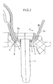
- FIG. 1 a section of a generator carrier 1 is shown in each case, over which a diffuser 2 extends. Between the two, the edge 11 of the inflation mouth of a gas bag 3 rests on the support surface 4 for fastening bolts 5.
- the gas bag 3 has two layers 3a, b in this region. The gas bag may also have other layers in this area. Concentric seams 6, 7 (FIGS. 2, 3) extend at the edge 11 of the inflation mouth of the gas bag.
- the generator carrier has a protective edge 10 and the edge 11 of the gas bag mouth extends through a gap 12 between the protective edge 10 and the diffuser 2 in this. Of the Protective edge causes the hot gases of the gas generator, not shown, reach the region of the edge 11 with the seam 6.
- the support surface 4 has a recess 8 corresponding to the seam 6, i. represents a circumferential groove.
- This groove can also be partially circumferential, provided that the seam is also formed accordingly.
- This recess has a wall 9 which is perpendicular to the pulling direction Z, in which the gas bag is pulled in its deployment.
- the gas bag 3 is claimed in its deployment in the region of the support surface 4 in the Z direction. As a result, the seam 6 is pressed against the wall 9. By this positive locking the withdrawal of the gas bag 3 is prevented from its attachment.
- the contact pressure of the fastening bolts 5 need only be so great that slipping out of the seam 6 from the recess 8 is prevented.
- two circumferential recesses 13, 14 are provided in the support surface 4, each having a wall 15 and 16 which are perpendicular to the pulling direction Z run, in which the gas bag is pulled in its unfolding.
- the depressions may be partially circumferential.
- the seam 6 is located in the recess 13 and in addition the seam 7 in the recess 14.
- seams 6, 7 instead of the seams 6, 7 also fixed rings can be attached to the gas bag, e.g. sewn be, which can be easily inserted in the intended shape of the wells in this.
- the recesses may extend around the fastening bolts 5, to which seams on the gas bag or to which the solid rings connected to the gas bag are assigned.
Landscapes
- Engineering & Computer Science (AREA)
- Mechanical Engineering (AREA)
- Air Bags (AREA)
Description
- Die Erfindung betrifft eine Anordnung zur Befestigung eines Gassacks in einem Fahrer-Airbagmodul nach dem Oberbegriff des Anspruchs 1 wie z. B. aus DE 3 939 021 bekannt ist.
- Aus dem europäischen Patent 1 113 948 B1 ist ein Airbagmodul mit Schwingungstilger für ein Lenkrad bekannt. Bei diesem Airbagmodul sind auf einem waagerechten Abschnitt des Modulgehäuses ein Diffusor und ein Gassack mittels Schrauben befestigt. Dabei liegt der Gassackmund flach zwischen diesem waagerechten Abschnitt und dem Diffusor und wird durch die Schrauben zwischen beiden geklemmt. Um ein Ausreißen des Gassackmundes beim Entfalten des Gassacks zu verhindern, müssen die Durchbrüche für die Schrauben im Gassack verstärkt ausgeführt werden. Weiterhin sind hohe Mutteranzugsmomente erforderlich, um eine sichere Klemmung zu erreichen. Das erfordert eine große Materialstärke und eine Vielzahl von Schrauben, wodurch diese Anordnungen schwer sind und einen erheblichen Montageaufwand erfordern.
- Weiterhin ist aus der deutschen Offenlegungsschrift 42 33 751 A1 ein Insassenrückhaltesystem bekannt, bei dem der Gassack an einem Gehäuse mittels Profilleisten befestigt ist, die in komplementären Gegenprofilen am Gehäuse formschlüssig einsetzbar sind, so daß an diesen Befestigunsstellen Befestigungsschrauben entfallen können. Diese Profilleisten können in einer Seitwärtsrichtung bezüglich ihrer Längsachse am Gegenprofil verrastet bzw. verriegelt werden oder in Längsrichtung in das Gegenprofil eingeschoben werden. Dadurch werden Montagekosten und Gewicht durch den Wegfall der Befestigungsschrauben eingespart.
- Diese Anordnung ist jedoch nur für Beifahrer-Airbags geeignet, da das Verrasten bzw. Verriegeln in Seitwärtsrichtung zunächst eine seitliche Verschiebung über das Gegenprofil hinweg erfordert, um dann anschließend in dieses eingedrückt zu werden. Das ist bei einem Beifahrer-Airbagmodul möglich, bei dem das Gehäuse in der Regel ein rechteckige Öffung für die Aufnahme des Einblasmundes des Airbags aufweist. Da der Gassack dehnbar ist, können deshalb zwei in Richtung der Längsseiten der Gehäuseöffnung verlaufende Profilleisten leicht über das Gegenprofil am Gehäuse bewegt werden. Die Befestigung des Gassacks an den Schmalseiten des Gehäuses erfolgt dann in herkömmlicher Weise mittels Bolzen oder Stiften.
- Da das Gehäuse eines Fahrer-Airbagmoduls wegen des meist zylindrischen Gasgenerators auch einen kreisrunde Öffnung aufweist, an der der Gassack befestigt werden muß, muß auch der Einblasmund des Gassacks kreisförmig sein. Das Profil müßte deshalb ebenfalls ein geschlossener starrer Kreisring sein, so daß ein seitliches Verschieben über das Gegenprofil am Gehäuse nicht möglich ist.
- Aber auch ein Einschieben des Profils in dessen Längsrichtung ist wegen der Kreisringform nicht möglich.
- Der Erfindung liegt die Aufgabe zugrunde, die Gassackbefestigung in einem Fahrerairbagmodul so zu verändern, daß Gewicht und Montagekosten eingespart werden und daß die Gassack-Klemmkraft reduziert werden kann.
- Erfindungsgemäß wird das gemäß den Merkmalen des Anspruchs 1 erreicht.
- Bei einer Anordnung zur Befestigung eines Gassacks in einem Fahrer-Airbagmodul, in dem der Gassack mittels einer Klemmverbindung befestigt ist, insbesondere für ein Airbagmodul mit Schwingungstilger, ist im Bereich der Klemmverbindung mindestens ein formschlüssiger Verbindungsabschnitt vorgesehen. Durch die Kombination der Klemmverbindung mit einer formschlüssigen Verbindung im Bereich der Klemmverbindung ist es einerseits möglich, die formschlüssige Verbindung so zu gestalten, daß sie auch bei kreisrunder Einblasöffnung des Gassacks und entsprechender Öffnung im Modulgehäuse leicht montierbar ist und andererseits können wegen des Formschlusses die Klemmkräfte verringert werden, d.h., es sind weniger Verbindungsschrauben erforderlich. Da der Gassack nicht allein durch Formschluß am Gehäuse gehalten wird, sondern zusätzlich durch die Klemmkräfte, sind die Gestaltungsmöglichkeiten für die formschlüssige Verbindung vielfältig.
- Die formschlüssige Klemmverbindung ist vorzugsweise zwischen einem Generatorträger und einem Diffusor des Airbagmoduls vorgesehen.
- Erfindungsgemäβ ist im Generatorträger mindestens eine Vertiefung für mindestens einen am Gassack vorhandenen Vorsprung vorgesehen, wobei die Vertiefung so ausgebildet ist, daß der Vorsprung zumindest bei Belastung in Zugrichtung des Gassacks bei dessen Entfaltung an einer Wand der Vertiefung anliegt. Der Vorteil besteht darin, daß wegen der zusätzlichen Klemmung eine einfache Vertiefung, z. B. Nut oder Rille ausreicht, um einen Formschluß zu erzielen. Da die Klemmung nur die Aufgabe hat, das Herausrutschen des Vorsprungs des Gassacks aus der Vertiefung im Falle der Entfaltung des Gassacks zu verhindern, können die Klemmkräfte wesentlich geringer sein, als bei einer reinen kraftschlüssigen Befestigung des Gassacks. Andererseits ist wegen der möglichen einfachen Form der Vertiefung das Einlegen des Vorsprungs des Gassacks in die Vertiefung einfach. Durch die Verringerung der Klemmkräfte wird die Funktionsbeeinträchtigung des Gasgenerators als Schwingungstilger verhindert.
- Es reicht aus, daß die Vertiefung an der Seite, an der der Vorsprung bei Entfaltung des Gassacks anliegt, eine zumindest annähernd senkrecht bezüglich der Zugrichtung des Gassacks verlaufende Wand aufweist.
- Es ist zweckmäßig, mindestens eine umlaufende Vertiefung vorzusehen, die entsprechend der Gehäuseöffnung für die Aufnahme des Einblasmundes des Gassacks verläuft. In einer weiteren Ausgestaltung sind zwei konzentrisch verlaufende Vertiefungen vorgesehen. Die umlaufende Vertiefung kann auch mindestens eine Unterbrechung aufweisen, z.B. für den Angußpunkt des Generatorträgers.
- Die Vertiefungen sind vorzugsweise auf der Auflagefläche für Befestigungsbolzen für die Klemmung des Gassacks vorgesehen.
- In einer Ausführung sind Vertiefungen um Befestigungsbolzen herum für die Klemmung des Gassacks vorgesehen.
- Als Vorsprung ist in einer Ausführungsform mindestens eine am Rand des Einblasmundes des Gassacks vorhandene Naht vorgesehen. Der Formschluß zwischen der Naht und der Vertiefung reicht wegen der zusätzlich vorgesehenen Klemmkraft aus, um den Gassack bei seiner Entfaltung sicher zu halten.
- Als Vorsprung kann aber auch mindestens ein mit dem Gassack verbundenes Bauteil vorgesehen sein, das vorzugsweise ein kreisringförmiges Profil aufweist. Der Vorteil der Erfindung ist, daß sich ein solches Profil, selbst wenn es starr ist, bei der Montage des Gassacks wegen der einfachen Vertiefung leicht in diese einlegen läßt.
- In einer weiteren Ausgestaltung der Erfindung ist vorgesehen, daß der Generatorträger innerhalb des Diffusors einen in dessen Richtung weisenden Schutzrand aufweist, wobei sich der Rand des Einblasmundes mindestens bis in einen Spalt zwischen dem Schutzrand und dem Diffusor erstreckt. Dadurch wird der Gassack, insbesondere im Bereich der Vorsprünge am Gassack, vor dem direkten Gasstrahl aus dem Gasgenerator geschützt, so daß eine thermische Versiegelung der Gewebekante des Einblasmundes entfallen kann.
- Die Erfindung soll in Ausführungsbeispielen anhand von Zeichnungen erläutert werden. Es zeigen:
- Fig. 1
- Querschnitte durch je einen Abschnitt eines Generatorträgers und durch einen Diffusorabschnitt;
- Fig. 2
- die Einzelheit A der Fig. 1 mit einer ersten Ausführungsform der Gassackbefestigung;
- Fig. 3
- die Einzelheit B der Fig. 1 mit einer zweiten Ausführungsform der Gassackbefestigung.
- In der Fig. 1 ist jeweils ein Abschnitt eines Generatorträgers 1 dargestellt, über den sich ein Diffusor 2 erstreckt. Zwischen beiden liegt der Rand 11 des Einblasmundes eines Gassacks 3 auf der Auflagefläche 4 für Befestigungsbolzen 5. Der Gassack 3 weist in diesem Bereich zwei Lagen 3a, b auf. Der Gassack kann in diesem Bereich aber auch weitere Lagen aufweisen. Am Rand 11 des Einblasmundes des Gassacks verlaufen konzentrische Nähte 6, 7 (Fig. 2, 3). Der Generatorträger weist einen Schutzrand 10 auf und der Rand 11 des Gassackmundes erstreckt sich durch einen Spalt 12 zwischen dem Schutzrand 10 und dem Diffusor 2 in diesen hinein. Der Schutzrand bewirkt, daß die heißen Gase des nicht dargestellten Gasgenerators den Bereich des Randes 11 mit der Naht 6 nicht erreichen.
- In der ersten Ausführungsform, die links der Mittellinie in der Fig. 1 sowie in der Fig 2 dargestellt ist, weist die Auflagefläche 4 eine Vertiefung 8 auf, die entsprechend der Naht 6 verläuft, d.h. eine umlaufende Nut darstellt. Diese Nut kann aber auch teilweise umlaufend sein, sofern die Naht ebenfalls entsprechend ausgebildet ist. Diese Vertiefung weist eine Wand 9 auf, die senkrecht bezüglich der Zugrichtung Z verläuft, in die der Gassack bei seiner Entfaltung gezogen wird. Durch Anziehen der Befestigungsbolzen 5 wird die Naht 6 auf der Seite der Gassacklage 3a in die Vertiefung 8 gedrückt. Auf der Seite der Gassacklage 3b wird die Naht 6 wegen des Fehlens einer entsprechenden Vertiefung im Diffusor 2 in diese Gassacklage gedrückt. Die Naht 7 wird bei beiden Gassacklagen 3a, b wegen des Fehlens von Vertiefungen im Generatorträger 1 und im Diffusor 2 in diese Gassacklagen gedrückt.
- Der Gassack 3 wird bei seiner Entfaltung im Bereich der Auflagefläche 4 in Z-Richtung beansprucht. Dadurch wird die Naht 6 an die Wand 9 gedrückt. Durch diesen Formschluß wird das Herausziehen des Gassacks 3 aus seiner Befestigung verhindert. Der Anpreßdruck der Befestigungsbolzen 5 muß lediglich so groß sein, daß das Herausrutschen der Naht 6 aus der Vertiefung 8 verhindert wird.
- Bei der zweiten Ausführungsform, die rechts der Mittellinie der Fig. 1 sowie in der Fig. 3 dargestellt ist, sind in der Auflagefläche 4 zwei umlaufende Vertiefungen 13, 14 vorgesehen, die jeweils eine Wand 15 bzw. 16 aufweisen, die senkrecht bezüglich der Zugrichtung Z verlaufen, in die der Gassack bei seiner Entfaltung gezogen wird. Wie bei der ersten Ausführungsform können auch bei dieser Ausführungsform die Vertiefungen teilweise umlaufend sein. Die Naht 6 liegt in der Vertiefung 13 und zusätzlich die Naht 7 in der Vertiefung 14. Damit wird mit größerer Sicherheit das Herausreißen des Gassacks aus der Befestigung verhindert.
- Anstelle der Nähte 6, 7 können auch feste Ringe am Gassack angebracht, z.B. angenäht, sein, die bei der vorgesehenen Form der Vertiefungen problemlos in diese eingelegt werden können.
- Weiterhin können die Vertiefungen um die Befestigungsbolzen 5 herum verlaufen, denen Nähte am Gassack bzw. denen die mit dem Gassack verbundenen festen Ringe zugeordnet sind.
- Infolge der Klemmwirkung des auf dem Rand 11 des Einblasmundes aufliegenden Diffusorrandes 2a sind bei dieser kombinierten form- und kraftschlüsigen Klemmung wesentlich weniger Befestigungsbolzen erforderlich als bei einer rein kraftschlüssigen Klemmung des Gassacks. 3 bis 4 Befestigungsbolzen sind für eine sichere Klemmung ausreichend.
Claims (12)
- Anordnung zur Befestigung eines Gassacks in einem Fahrer-Airbagmodul, in dem der Gassack mittels einer Klemmverbindung befestigt ist, wobei im Bereich der Klemmverbindung mindestens ein formschlüssiger Verbindungsabschnitt vorgesehen ist, insbesondere für ein Airbagmodul mit Schwingungstilger,
dadurch gekennzeichnet, dass in einem Generatorträger (1) mindestens eine Vertiefung (8) für mindestens einen am Gassack vorhandenen Vorsprung (6) vorgesehen ist, wobei die Vertiefung (8) so ausgebildet ist, dass der Vorsprung (6) zumindest bei Belastung in Zugrichtung (Z) des Gassacks (3) bei dessen Entfaltung an einer Wand (9) der Vertiefung (8) anliegt - Anordnung nach Anspruch 1, dadurch gekennzeichnet, dass die formschlüssige Klemmverbindung zwischen dem Generatorträger (1) und einem Diffusor (2) des Airbagmoduls vorgesehen ist.
- Anordnung nach Anspruch 1 oder 2, dadurch gekennzeichnet, daß die Vertiefung (8) an der Seite, an der der Vorsprung (6) bei Entfaltung des Gassacks (3) anliegt, eine zumindest annähernd senkrecht bezüglich der Zugrichtung (Z) des Gassacks (3) verlaufende Wand (9) aufweist.
- Anordnung nach mindestens einem der Ansprüche 1 bis 3, dadurch gekennzeichnet, daß mindestens eine umlaufende Vertiefung (8) vorgesehen ist.
- Anordnung nach Anspruch 4, dadurch gekennzeichnet, daß zwei konzentrisch verlaufende Vertiefungen (13, 14) vorgesehen sind.
- Anordnung nach Anspruch 4 oder 5, dadurch gekennzeichnet, daß die umlaufende Vertiefung mindestens eine Unterbrechung aufweist.
- Anordnung nach mindestens einem der vorhergehenden Ansprüche, dadurch gekennzeichnet, dass die Vertiefungen auf der Auflagefläche (4) für Befestigungsbolzen (5) für die Klemmung des Gassacks (3) vorgesehen sind.
- Anordnung nach mindestens einem der vorhergehenden Ansprüche, dadurch gekennzeichnet, dass Vertiefungen um die Befestigungsbolzen (5) herum für die Klemmung des Gassacks (3) vorgesehen sind.
- Anordnung nach mindestens einem der vorhergehenden Ansprüche, dadurch gekennzeichnet, dass als Vorsprung mindestens eine am Rand (11) eines Einblasmundes des Gassacks (3) vorhandene Naht (6, 7) vorgesehen ist.
- Anordnung nach mindestens einem der vorhergehenden Ansprüche, dadurch gekennzeichnet, dass als Vorsprung mindestens ein mit dem Gassack (3) verbundenes Bauteil vorgesehen ist.
- Anordnung nach Anspruch 10, dadurch gekennzeichnet, dass das Bauteil ein kreisringförmiges Profil aufweist.
- Anordnung nach mindestens einem der vorhergehenden Ansprüche, dadurch gekennzeichnet; dass der Generatorträger (1) innerhalb des Diffusors (2) einen in dessen Richtung weisenden Schutzrand (10) aufweist, wobei sich der Rand (11) des Einblasmundes mindestens bis in einen Spalt (12) zwischen dem Schutzrand (10) und dem Diffusor (2) erstreckt.
Applications Claiming Priority (2)
| Application Number | Priority Date | Filing Date | Title |
|---|---|---|---|
| DE20315347U DE20315347U1 (de) | 2003-09-30 | 2003-09-30 | Anordnung zur Befestigung eines Gassacks in einem Fahrer-Airbagmodul |
| DE20315347U | 2003-09-30 |
Publications (2)
| Publication Number | Publication Date |
|---|---|
| EP1520755A1 EP1520755A1 (de) | 2005-04-06 |
| EP1520755B1 true EP1520755B1 (de) | 2006-03-22 |
Family
ID=29796888
Family Applications (1)
| Application Number | Title | Priority Date | Filing Date |
|---|---|---|---|
| EP04077628A Expired - Lifetime EP1520755B1 (de) | 2003-09-30 | 2004-09-20 | Anordnung zur Befestigung eines Gassacks in einem Fahrer-Airbagmodul |
Country Status (5)
| Country | Link |
|---|---|
| US (1) | US7584986B2 (de) |
| EP (1) | EP1520755B1 (de) |
| JP (1) | JP4189370B2 (de) |
| CN (1) | CN100404322C (de) |
| DE (2) | DE20315347U1 (de) |
Families Citing this family (8)
| Publication number | Priority date | Publication date | Assignee | Title |
|---|---|---|---|---|
| DE202007018451U1 (de) | 2007-05-22 | 2008-08-07 | Takata-Petri Ag | Aufblaseinrichtung einer Airbagbaugruppe für ein Kraftfahrzeug |
| JP5117838B2 (ja) * | 2007-12-13 | 2013-01-16 | タカタ株式会社 | エアバッグ装置 |
| US7926837B2 (en) * | 2009-02-03 | 2011-04-19 | Trw Vehicle Safety Systems Inc. | Inflatable vehicle occupant protection device with inflation fluid deflector |
| DE102011008372A1 (de) * | 2011-01-12 | 2012-07-12 | Daimler Ag | Airbag, insbesondere für einen Kraftwagen |
| JP2013203343A (ja) * | 2012-03-29 | 2013-10-07 | Toyoda Gosei Co Ltd | エアバッグ装置 |
| DE102014000642A1 (de) * | 2014-01-16 | 2015-07-16 | Autoliv Development Ab | Airbag-Modul |
| DE202014008432U1 (de) * | 2014-10-23 | 2016-01-26 | Trw Automotive Safety Systems Gmbh | Vorrichtung zur schwingfähigen Befestigung eines Gasgenerators in einem Airbagmodul |
| US9849855B1 (en) | 2016-06-01 | 2017-12-26 | Ford Global Technologies, Llc | Seatbelt airbag assembly |
Family Cites Families (33)
| Publication number | Priority date | Publication date | Assignee | Title |
|---|---|---|---|---|
| US4913461A (en) * | 1988-12-27 | 1990-04-03 | Talley Automotive Products, Inc. | Airbag module and method of making same |
| US4986569A (en) * | 1989-06-19 | 1991-01-22 | Automotive Systems Laboratory, Inc. | Airbag attachment system |
| CN2071153U (zh) | 1989-11-20 | 1991-02-13 | 朱争明 | 气鸣车铃 |
| DE3939021C1 (en) * | 1989-11-25 | 1990-11-22 | Bayern-Chemie Gesellschaft Fuer Flugchemische Antriebe Mbh, 8261 Aschau, De | Gas generator for inflatable protection bag for motor cars - has light metal casing enclosing propellant laden reaction chamber joined to expansion and filter chamber |
| US5176400A (en) * | 1991-07-09 | 1993-01-05 | Textron Inc. | Air bag mounting system |
| US5275431A (en) * | 1991-09-18 | 1994-01-04 | Trw Inc. | Air bag inflator assembly |
| JPH05162602A (ja) | 1991-12-17 | 1993-06-29 | Takata Kk | エアバッグ装置のエアバッグ取付構造 |
| JPH05178150A (ja) | 1992-01-06 | 1993-07-20 | Takata Kk | 助手席用エアバッグ装置におけるコンテナへのエアバッグの取付構造 |
| JPH0659164A (ja) | 1992-08-05 | 1994-03-04 | Fujitsu Ltd | 光モジュールの搭載構造 |
| DE4233751C2 (de) * | 1992-10-07 | 1994-12-22 | Daimler Benz Ag | Insassenrückhaltesystem |
| JPH06122354A (ja) * | 1992-10-12 | 1994-05-06 | Bridgestone Corp | エアバック装置 |
| US5518266A (en) * | 1994-10-20 | 1996-05-21 | Trw Inc. | Vehicle safety apparatus including inflatable restraint |
| US5577763A (en) * | 1995-03-29 | 1996-11-26 | Trw Inc. | Air bag mounting structure and method |
| US5692770A (en) * | 1995-09-15 | 1997-12-02 | Breed Automotive Technology, Inc. | Modular steering wheel and airbag combination |
| US5687986A (en) * | 1995-12-28 | 1997-11-18 | Precision Fabric Group | Attachment device for an inflatable protective cushion |
| US5692771A (en) * | 1996-03-12 | 1997-12-02 | Trw Inc. | Vehicle occupant protection apparatus |
| JP3792796B2 (ja) | 1996-08-30 | 2006-07-05 | 日本プラスト株式会社 | エアバッグ装置 |
| DE29616916U1 (de) * | 1996-09-27 | 1997-01-30 | Trw Occupant Restraint Systems Gmbh, 73551 Alfdorf | Gassack-Modul für ein Fahrzeuginsassen-Rückhaltesystem |
| DE19645217A1 (de) | 1996-11-02 | 1998-05-07 | Mst Automotive Gmbh | Airbag-Modul für Kraftfahrzeuglenkräder |
| DE29816923U1 (de) * | 1998-09-16 | 1998-11-26 | Petri Ag, 63743 Aschaffenburg | Lenkrad mit Airbagmodul |
| US6250665B1 (en) * | 1998-12-15 | 2001-06-26 | Trw Vehicle Safety Systems Inc. | Retainer structure for an inflatable vehicle occupant protection device |
| DE19858691B4 (de) * | 1998-12-18 | 2010-01-07 | Delphi Automotive Systems Deutschland Gmbh | Luftsackmodul für Kraftfahrzeuge |
| JP2001247010A (ja) * | 1999-12-28 | 2001-09-11 | Takata Corp | 乗員保護装置 |
| DE10065463C2 (de) * | 2000-05-19 | 2003-12-18 | Trw Automotive Safety Sys Gmbh | Airbagmodul |
| US6431583B1 (en) * | 2001-02-28 | 2002-08-13 | Autoliv Asp, Inc. | Inflatable knee bolster with external tethering |
| US6702318B2 (en) * | 2001-04-11 | 2004-03-09 | Autoliv Asp, Inc. | Vehicle occupant restraint module with disk inflator |
| US6616184B2 (en) * | 2001-04-25 | 2003-09-09 | Trw Vehicle Safety Systems Inc. | Vehicle occupant protection apparatus with inflation volume and shape control |
| CN2504487Y (zh) * | 2001-08-23 | 2002-08-07 | 姜浩 | 气囊式无骨架灯笼 |
| DE20114507U1 (de) * | 2001-09-03 | 2002-01-24 | Trw Automotive Safety Sys Gmbh | Gassackmodul |
| DE10204642B4 (de) * | 2002-02-05 | 2010-08-12 | Key Safety Systems, Inc., Sterling Heights | Airbagmodul mit einer Grundplatte, Verfahren zum Strecken eines Gassacks eines Airbagmoduls und Vorrichtung zum Ausführen des Verfahrens |
| DE20317611U1 (de) * | 2003-11-14 | 2004-04-01 | Trw Automotive Safety Systems Gmbh | Gassackmodul |
| JP4345637B2 (ja) * | 2004-10-21 | 2009-10-14 | 豊田合成株式会社 | エアバッグ装置 |
| DE102004056010B4 (de) * | 2004-11-19 | 2007-03-22 | Key Safety Systems, Inc., Sterling Heights | Luftsackbefestigung für Beifahrer Airbag |
-
2003
- 2003-09-30 DE DE20315347U patent/DE20315347U1/de not_active Expired - Lifetime
-
2004
- 2004-09-20 EP EP04077628A patent/EP1520755B1/de not_active Expired - Lifetime
- 2004-09-20 DE DE502004000379T patent/DE502004000379D1/de not_active Expired - Lifetime
- 2004-09-29 US US10/951,790 patent/US7584986B2/en not_active Expired - Fee Related
- 2004-09-30 JP JP2004289062A patent/JP4189370B2/ja not_active Expired - Fee Related
- 2004-09-30 CN CNB2004100833558A patent/CN100404322C/zh not_active Expired - Fee Related
Also Published As
| Publication number | Publication date |
|---|---|
| DE20315347U1 (de) | 2003-12-18 |
| EP1520755A1 (de) | 2005-04-06 |
| US20050067818A1 (en) | 2005-03-31 |
| JP2005104464A (ja) | 2005-04-21 |
| US7584986B2 (en) | 2009-09-08 |
| JP4189370B2 (ja) | 2008-12-03 |
| CN1613693A (zh) | 2005-05-11 |
| DE502004000379D1 (de) | 2006-05-11 |
| CN100404322C (zh) | 2008-07-23 |
Similar Documents
| Publication | Publication Date | Title |
|---|---|---|
| EP1048531B1 (de) | Seitenaufprall-Schutzeinrichtung für Fahrzeuginsassen | |
| DE19941269B4 (de) | Energieabsorbierende Fahrzeugverkleidung mit Airbag | |
| DE29616904U1 (de) | Schutzeinrichtung für Fahrzeuginsassen | |
| DE69831040T2 (de) | Kopfschutzende Airbagvorrichtung | |
| DE10004483C2 (de) | Airbagvorrichtung zur Anordnung im Dachrahmenbereich eines Kraftfahrzeuges | |
| EP0769428A2 (de) | Gassack-Seitenaufprall-Schutzeinrichtung | |
| EP0944501B9 (de) | Airbag, insbesondere seitenairbag | |
| EP0653334B1 (de) | Airbag-Gehäuse und dessen Befestigung | |
| WO2000037286A2 (de) | Verkleidungsmodul mit airbag | |
| DE29818411U1 (de) | Gassackmodul | |
| DE102011117872B4 (de) | Fahrgastschutzvorrichtung eines Fahrzeugs | |
| EP1520755B1 (de) | Anordnung zur Befestigung eines Gassacks in einem Fahrer-Airbagmodul | |
| DE19703767B4 (de) | Gehäuse für den Gassack in einem Kraftfahrzeug | |
| DE19731973A1 (de) | Gassack-Baugruppe | |
| EP2958776B1 (de) | Airbagmodul für ein kraftfahrzeug | |
| EP1324900A1 (de) | Gehäuse für einen aufblasbaren gassack eines kraftfahrzeuges | |
| DE102004014742B4 (de) | Fahrzeug mit Vorhang-Airbag | |
| DE20313108U1 (de) | Airbagmodul mit Gasgenerator | |
| EP1971505B1 (de) | Gassackbefestigung in einem airbagmodul mittels einer klemmverbindung | |
| EP1314620B2 (de) | Mittel zur Befestigung eines Airbagmoduls in einem Kraftfahrzeug | |
| EP0832791B1 (de) | Gassack-Modul für ein Fahrzeuginsassen-Rückhaltesystem | |
| EP1182099B1 (de) | Fahrzeuginsassen-Schutzvorrichtung mit Seitengassack | |
| DE19909426B4 (de) | Airbageinheit | |
| EP1122133B1 (de) | Aktiver Knieschutz mit Luftsack, Lastverteilerplatte und abreissbaren Verbindungselementen | |
| EP1724162B1 (de) | Instrumententafel mit einem Luftsackmodul und Herstellungsverfahren dafür |
Legal Events
| Date | Code | Title | Description |
|---|---|---|---|
| PUAI | Public reference made under article 153(3) epc to a published international application that has entered the european phase |
Free format text: ORIGINAL CODE: 0009012 |
|
| AK | Designated contracting states |
Kind code of ref document: A1 Designated state(s): AT BE BG CH CY CZ DE DK EE ES FI FR GB GR HU IE IT LI LU MC NL PL PT RO SE SI SK TR |
|
| AX | Request for extension of the european patent |
Extension state: AL HR LT LV MK |
|
| 17P | Request for examination filed |
Effective date: 20050601 |
|
| GRAP | Despatch of communication of intention to grant a patent |
Free format text: ORIGINAL CODE: EPIDOSNIGR1 |
|
| AKX | Designation fees paid |
Designated state(s): DE FR GB SE |
|
| GRAS | Grant fee paid |
Free format text: ORIGINAL CODE: EPIDOSNIGR3 |
|
| GRAA | (expected) grant |
Free format text: ORIGINAL CODE: 0009210 |
|
| AK | Designated contracting states |
Kind code of ref document: B1 Designated state(s): DE FR GB SE |
|
| REG | Reference to a national code |
Ref country code: GB Ref legal event code: FG4D Free format text: NOT ENGLISH |
|
| REF | Corresponds to: |
Ref document number: 502004000379 Country of ref document: DE Date of ref document: 20060511 Kind code of ref document: P |
|
| REG | Reference to a national code |
Ref country code: SE Ref legal event code: TRGR |
|
| GBT | Gb: translation of ep patent filed (gb section 77(6)(a)/1977) |
Effective date: 20060614 |
|
| ET | Fr: translation filed | ||
| PLBE | No opposition filed within time limit |
Free format text: ORIGINAL CODE: 0009261 |
|
| STAA | Information on the status of an ep patent application or granted ep patent |
Free format text: STATUS: NO OPPOSITION FILED WITHIN TIME LIMIT |
|
| 26N | No opposition filed |
Effective date: 20061227 |
|
| PGFP | Annual fee paid to national office [announced via postgrant information from national office to epo] |
Ref country code: SE Payment date: 20100913 Year of fee payment: 7 |
|
| PGFP | Annual fee paid to national office [announced via postgrant information from national office to epo] |
Ref country code: GB Payment date: 20100916 Year of fee payment: 7 |
|
| GBPC | Gb: european patent ceased through non-payment of renewal fee |
Effective date: 20110920 |
|
| REG | Reference to a national code |
Ref country code: SE Ref legal event code: EUG |
|
| PG25 | Lapsed in a contracting state [announced via postgrant information from national office to epo] |
Ref country code: GB Free format text: LAPSE BECAUSE OF NON-PAYMENT OF DUE FEES Effective date: 20110920 |
|
| REG | Reference to a national code |
Ref country code: DE Ref legal event code: R082 Ref document number: 502004000379 Country of ref document: DE Representative=s name: MAIKOWSKI & NINNEMANN PATENTANWAELTE, DE |
|
| REG | Reference to a national code |
Ref country code: DE Ref legal event code: R082 Ref document number: 502004000379 Country of ref document: DE Representative=s name: MAIKOWSKI & NINNEMANN PATENTANWAELTE, DE Effective date: 20120904 Ref country code: DE Ref legal event code: R081 Ref document number: 502004000379 Country of ref document: DE Owner name: TAKATA AKTIENGESELLSCHAFT, DE Free format text: FORMER OWNER: TAKATA-PETRI AG, 63743 ASCHAFFENBURG, DE Effective date: 20120904 Ref country code: DE Ref legal event code: R082 Ref document number: 502004000379 Country of ref document: DE Representative=s name: MAIKOWSKI & NINNEMANN PATENTANWAELTE PARTNERSC, DE Effective date: 20120904 |
|
| PG25 | Lapsed in a contracting state [announced via postgrant information from national office to epo] |
Ref country code: SE Free format text: LAPSE BECAUSE OF NON-PAYMENT OF DUE FEES Effective date: 20110921 |
|
| REG | Reference to a national code |
Ref country code: FR Ref legal event code: PLFP Year of fee payment: 12 |
|
| PGFP | Annual fee paid to national office [announced via postgrant information from national office to epo] |
Ref country code: DE Payment date: 20150916 Year of fee payment: 12 |
|
| PGFP | Annual fee paid to national office [announced via postgrant information from national office to epo] |
Ref country code: FR Payment date: 20150629 Year of fee payment: 12 |
|
| REG | Reference to a national code |
Ref country code: DE Ref legal event code: R119 Ref document number: 502004000379 Country of ref document: DE |
|
| REG | Reference to a national code |
Ref country code: FR Ref legal event code: ST Effective date: 20170531 |
|
| PG25 | Lapsed in a contracting state [announced via postgrant information from national office to epo] |
Ref country code: DE Free format text: LAPSE BECAUSE OF NON-PAYMENT OF DUE FEES Effective date: 20170401 Ref country code: FR Free format text: LAPSE BECAUSE OF NON-PAYMENT OF DUE FEES Effective date: 20160930 |