EP1519667B1 - Vorrichtung zur befestigung eines flexiblen laminarelements an einem rahmen - Google Patents
Vorrichtung zur befestigung eines flexiblen laminarelements an einem rahmen Download PDFInfo
- Publication number
- EP1519667B1 EP1519667B1 EP03762582A EP03762582A EP1519667B1 EP 1519667 B1 EP1519667 B1 EP 1519667B1 EP 03762582 A EP03762582 A EP 03762582A EP 03762582 A EP03762582 A EP 03762582A EP 1519667 B1 EP1519667 B1 EP 1519667B1
- Authority
- EP
- European Patent Office
- Prior art keywords
- bearing structure
- laminar body
- frame
- laminar
- groove
- Prior art date
- Legal status (The legal status is an assumption and is not a legal conclusion. Google has not performed a legal analysis and makes no representation as to the accuracy of the status listed.)
- Expired - Lifetime
Links
- 230000008878 coupling Effects 0.000 claims description 5
- 238000010168 coupling process Methods 0.000 claims description 5
- 238000005859 coupling reaction Methods 0.000 claims description 5
- 239000004744 fabric Substances 0.000 claims description 5
- 239000004800 polyvinyl chloride Substances 0.000 claims description 5
- 229920002994 synthetic fiber Polymers 0.000 claims description 5
- 238000003466 welding Methods 0.000 claims description 4
- 238000004026 adhesive bonding Methods 0.000 claims description 2
- 238000000926 separation method Methods 0.000 claims description 2
- 239000004952 Polyamide Substances 0.000 description 3
- 239000000463 material Substances 0.000 description 3
- 229920002647 polyamide Polymers 0.000 description 3
- 238000004140 cleaning Methods 0.000 description 2
- 239000011888 foil Substances 0.000 description 2
- 239000012535 impurity Substances 0.000 description 2
- 239000004033 plastic Substances 0.000 description 2
- 229920003023 plastic Polymers 0.000 description 2
- 229920000915 polyvinyl chloride Polymers 0.000 description 2
- 238000010420 art technique Methods 0.000 description 1
- 238000000151 deposition Methods 0.000 description 1
- 230000006866 deterioration Effects 0.000 description 1
- 238000001746 injection moulding Methods 0.000 description 1
- 238000004519 manufacturing process Methods 0.000 description 1
- 239000010902 straw Substances 0.000 description 1
- 239000004758 synthetic textile Substances 0.000 description 1
Images


Classifications
-
- A—HUMAN NECESSITIES
- A47—FURNITURE; DOMESTIC ARTICLES OR APPLIANCES; COFFEE MILLS; SPICE MILLS; SUCTION CLEANERS IN GENERAL
- A47C—CHAIRS; SOFAS; BEDS
- A47C31/00—Details or accessories for chairs, beds, or the like, not provided for in other groups of this subclass, e.g. upholstery fasteners, mattress protectors, stretching devices for mattress nets
- A47C31/02—Upholstery attaching means
- A47C31/023—Upholstery attaching means connecting upholstery to frames, e.g. by hooks, clips, snap fasteners, clamping means or the like
-
- A—HUMAN NECESSITIES
- A47—FURNITURE; DOMESTIC ARTICLES OR APPLIANCES; COFFEE MILLS; SPICE MILLS; SUCTION CLEANERS IN GENERAL
- A47C—CHAIRS; SOFAS; BEDS
- A47C1/00—Chairs adapted for special purposes
- A47C1/14—Beach chairs ; Chairs for outdoor use, e.g. chairs for relaxation or sun-tanning
- A47C1/143—Chaise lounges
-
- Y—GENERAL TAGGING OF NEW TECHNOLOGICAL DEVELOPMENTS; GENERAL TAGGING OF CROSS-SECTIONAL TECHNOLOGIES SPANNING OVER SEVERAL SECTIONS OF THE IPC; TECHNICAL SUBJECTS COVERED BY FORMER USPC CROSS-REFERENCE ART COLLECTIONS [XRACs] AND DIGESTS
- Y10—TECHNICAL SUBJECTS COVERED BY FORMER USPC
- Y10T—TECHNICAL SUBJECTS COVERED BY FORMER US CLASSIFICATION
- Y10T403/00—Joints and connections
- Y10T403/60—Biased catch or latch
- Y10T403/606—Leaf spring
-
- Y—GENERAL TAGGING OF NEW TECHNOLOGICAL DEVELOPMENTS; GENERAL TAGGING OF CROSS-SECTIONAL TECHNOLOGIES SPANNING OVER SEVERAL SECTIONS OF THE IPC; TECHNICAL SUBJECTS COVERED BY FORMER USPC CROSS-REFERENCE ART COLLECTIONS [XRACs] AND DIGESTS
- Y10—TECHNICAL SUBJECTS COVERED BY FORMER USPC
- Y10T—TECHNICAL SUBJECTS COVERED BY FORMER US CLASSIFICATION
- Y10T403/00—Joints and connections
- Y10T403/70—Interfitted members
- Y10T403/7018—Interfitted members including separably interposed key
Definitions
- the invention is about a bearing structure comprising of locking device for connecting a flexible laminar element to a frame, specifically suitable for being used in the making of structures apt to hold a person's body such as chairs, deck-chairs, sun-beds, and alike.
- Some state of the art locking devices are made of screws which are applied to the frame's perimeter in order to fix the flexible laminar element to the same frame.
- US 6,378,944 B1 discloses a seat and/or backrest covering for a chair in which a frame tensioned mesh-like fabric is penetrated by a large number of pins belonging to a load-bearing frame that surrounds the seat or backrest, a cover being also provided to be fitted in said load-bearing frame.
- a first inconvenience of the state of the art locking devices available on the market consists in that the assembly of the flexible laminar element to the frame is particularly difficult.
- a second inconvenience, related to the first one, consists in that the above-mentioned problem considerably affects both on the production times and costs.
- a further inconvenience consists in that the assembly must be carried out by expert personnel who flawlessly achieves the operation.
- the locking devices with synthetic strings have the inconvenience that the interlace of the strings which carries out the connection between the flexible laminar element and the frame is not very hygienic, because the strings are a vehicle for the depositing of dirt.
- the strings because they are freely accessible, can be subject to tampering or breaking thus jeopardizing the safety of the people who utilize these handworks.
- the application of the flexible laminar element to the frame turns out to be particularly easy and fit to be carried out with the aid of automatic machines as well.
- the invention likewise allows having a safe anchorage of the flexible foil to the frame, thus improving the safety of the user who lays him/herself on the structure.
- the bearing structure of the invention allows achieving a continuity between the flexible laminar element and the frame, thus considerably reducing the gaps wherein the impurities can get deposited and in the meanwhile by providing the entire structure with a particularly attractive line.
- the bearing structure comprising a locking device is made in such a manner that the part which is exposed to the sun rays is made of polyamide that under these circumstances is notoriously not subject to deterioration, while the part not exposed to sunlight is made of polyvinyl chloride (PVC).
- PVC polyvinyl chloride
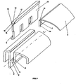
- the bearing structure of the invention is generally indicated with 1 in the following figures 1 and 2, where is shown with an isometric view and a longitudinal section respectively.
- the locking device connects a flexible laminar element 2, made of synthetic fibres, to a frame 3 in order to achieve a bearing structure 4, of which only a detail is illustrated, suitable for housing a person's body.
- the frame 3 it is preferably made of a plastic material through an injection moulding operation.
- the flexible laminar element instead, in other embodiments it could consist of a cloth also made of natural or mixed fibres, or it could take up the form of a net or alike made of a plastic material.
- the bearing structure comprises a locking device 1 which comprises a groove 5 obtained along the perimeter, generally indicated with 11, of the frame 3 and a shaped insert 6 which is pressed into the groove 5 in order to constrain the perimetral edge 7 of the flexible laminar element 2 between the groove 5 and the shaped insert 6.
- a plurality of openings is obtained inside the groove 5, in order to allow the passage of as many corresponding appendixes 9 present on the shaped insert 6 equipped with coupling means, generally indicated with 10, which snap the shaped insert 6 to the frame 3.
- the groove 5 has a profile 5' mainly with a U shape that is developed according to a longitudinal direction X along the frame 3.
- the openings 8 are obtained at the bottom 21 of the groove 5 along said longitudinal direction X.
- the shaped insert 6 comprises a first laminar body 12, made of a synthetic material, in this case of polyamide, with a mainly longitudinal development and equipped with the appendixes 9 and, at the opposite side, with a shaped head 13.
- the shaped insert 6 further comprises a second laminar body 14, made of polyvinyl chloride (PVC), it too with a mainly longitudinal development, which the perimetral edge 7 of the flexible laminar element 2 is applied to, in this case through welding.
- PVC polyvinyl chloride
- first laminar body 12 and the second laminar body 14 are pressed into the groove 5, they constrain the perimetral edge 7 of the flexible laminar element 2 to the frame 3 by arranging themselves juxtaposed and mutually in contact.
- the shaped head 13 which is arranged as cover to the groove 5 when the locking device 1 of the invention is in the operative mode, defines a first shoulder 15 on the first laminar body 12, which receives the second laminar body 14 and the second shoulder 16, opposed to the first shoulder 15, which matches the frame 3 inside of the groove 5.
- the first shoulder 15 has an opposing surface 17 slanted upwards and converging towards the first laminar body 12, which matches in a stable but removable manner the upper edge 19 of the second laminar body 14, so as to prevent the accidental separation of the latter when it gets applied to the first laminar body 12.
- the second shoulder 16 instead, has an opposing surface 18 slanted upwards but divergent from the first laminar body 12, which matches the frame 3.
- the operator juxtaposes the second laminar body 14 to the first laminar body 12, arranging them mainly parallel and so as to couple the perimetral edge 19 of the first one with the opposing surface 18 of the second one.
- the appendixes 9 of the first laminar body 12 pass through the corresponding openings 8 present at the bottom 21 of the groove 5.
- the application of the locking device 1 to the frame 3 ends with snapping the ends 20 of the appendixes 9 to the same frame 3 and with the positioning of the shaped head 13 of the first laminar body 12 as a cover for the groove 5.
- the polyamide shaped head 13 protects the second PVC laminar body 14 from sun rays exposure that otherwise, due exactly to the material which is made of, would damage it thus severely jeopardizing its functionality.
- the user will then be able either to change, according to his/her own needs and preferences, the type and colour of the flexible laminar element, or to replace it when it is particularly deteriorated.
- the bearing structure 4 obtained is in this case a sun-bed wherein a person can either lay on or lean on it.
- the flexible laminar element could be applied to the second laminar body of the shaped insert through glueing.
- the grooves could not be obtained along the entire perimeter of the frame of the bearing structure, but instead only along two parallel and opposing stretches of the same frame.
Landscapes
- Health & Medical Sciences (AREA)
- Dentistry (AREA)
- General Health & Medical Sciences (AREA)
- Connection Of Plates (AREA)
- Snaps, Bayonet Connections, Set Pins, And Snap Rings (AREA)
- Tents Or Canopies (AREA)
- Mutual Connection Of Rods And Tubes (AREA)
Claims (17)
- Eine Tragstruktur (4), eine Blockiervorrichtung (1) für die Befestigung eines Lamellenelements (2) an einem Rahmen (3) umfassend, dadurch gekennzeichnet, dass der Rahmen (3) eine Rille (5) umfasst, die wenigstens entlang eines Teils des Umfangs (11) des Rahmens (3) herausgearbeitet ist sowie einen geformten Einsatz (6) umfasst, der geeignet ist, in die Rille (5) gedrückt zu werden, um die Außenkante (7) des flexiblen Lamellenelements (2) zwischen der Rille (5) und dem geformten Einsatz (6) einzuklemmen, wobei innerhalb der Rille (5) eine Vielzahl von Öffnungen (8) angeordnet ist für den Durchgang ebenso vieler Ansatzstücke (9) des geformten Einsatzes (6), ausgestattet mit Kupplungsmitteln (10), die den geformten Einsatz (6) in den Rahmen (3) einschnappen lassen.
- Die Tragstruktur (4) gemäß Patentanspruch 1), dadurch gekennzeichnet, dass die Rille (5) ein im Wesentlichen U-förmiges Profil (5') hat, das in Längsrichtung (X) am Rahmen (3) entlang verläuft.
- Die Tragstruktur (4) gemäß Patentanspruch 2), dadurch gekennzeichnet, dass die Öffnungen (8) aus dem Boden (21) der in Längsrichtung (X) verlaufenden, U-förmigen Rille (5) gewonnen sind.
- Die Tragstruktur (4) gemäß Patentanspruch 1), dadurch gekennzeichnet, dass der geformte Einsatz (6) Folgendes umfasst:- einen ersten, im Wesentlichen länglichen Lamellenkörper (12), der mit den Ansatzstücken (9) versehen ist sowie mit einem geformten Kopf (13), der an der den Ansatzstücken (9) gegenüber liegenden Seite positioniert ist;- einen zweiten, im Wesentlichen länglichen Lamellenkörper (14), an dem die Außenkante (7) des flexiblen Lamellenelements (2) befestigt ist,wobei der erste Lamellenkörper (12) und der zweite Lamellenkörper (14) nebeneinander liegen und sich gegenseitig berühren, um die Außenkante (7) des flexiblen Lamellenelements (2) am Rahmen (3) festzuklemmen, wenn sie in die Rille (5) gedrückt werden.
- Die Tragstruktur (4) gemäß Patentanspruch 4), dadurch gekennzeichnet, dass der geformte Kopf (13) des ersten Lamellenkörpers (12) als Deckel der Rille (5) angeordnet ist.
- Die Tragstruktur (4) gemäß Patentanspruch 5), dadurch gekennzeichnet, dass der geformte Kopf (13) eine erste Schulter (15) am ersten Lamellenkörper (12) definiert, die geeignet ist, den zweiten Lamellenkörper (14) aufzunehmen, und eine zweite Schulter (16) definiert, die der ersten Schulter (15) gegenüber liegt und geeignet ist, mit dem Rahmen (3) innerhalb der Rille (5) zusammenzupassen.
- Die Tragstruktur (4) gemäß Patentanspruch 6), dadurch gekennzeichnet, dass die erste Schulter (15) eine entgegen gesetzte Oberfläche (17) hat, die schräg nach oben verläuft und zum ersten Lamellenkörper (12) konvergiert, um die Trennung des zweiten Lamellenkörpers (14) vom ersten Lamellenkörper (12) zu verhindern.
- Die Tragstruktur (4) gemäß Patentanspruch 6), dadurch gekennzeichnet, dass die zweite Schulter (16) eine entgegen gesetzte Oberfläche (18) hat, die schräg nach oben verläuft und vom ersten Lamellenkörper (12) divergiert.
- Die Tragstruktur (4) gemäß Patentanspruch 8), dadurch gekennzeichnet, dass der zweite Lamellenkörper (14) eine Oberkante (19) hat, die geeignet ist, auf eine stabile, jedoch abnehmbare Weise in die entgegen gesetzte Oberfläche (17) der ersten Schulter (15) zu passen.
- Die Tragstruktur (4) gemäß Patentanspruch 1), dadurch gekennzeichnet, dass die Kupplungsmittel (10) aus dem zu einer Hakenform gebogenen Ende (20) der Ansatzstücke (9) bestehen.
- Die Tragstruktur (4) gemäß Patentanspruch 4), dadurch gekennzeichnet, dass der erste Lamellenkörper (12) des geformten Einsatzes (6) aus Kunststoff besteht.
- Die Tragstruktur (4) gemäß Patentanspruch 4), dadurch gekennzeichnet, dass der zweite Lamellenkörper (14) des geformten Einsatzes (6) aus Polyvinylchlorid (PVC) besteht.
- Die Tragstruktur (4) gemäß Patentanspruch 4), dadurch gekennzeichnet, dass die Außenkante (7) des flexiblen Lamellenelements (2) am zweiten Lamellenkörper (14) des geformten Einsatzes (6) angeschweißt ist.
- Die Tragstruktur (4) gemäß Patentanspruch 4), dadurch gekennzeichnet, dass die Außenkante (7) des flexiblen Lamellenelements (2) am zweiten Lamellenkörper (14) des geformten Einsatzes (6) angeklebt ist.
- Die Tragstruktur (4) gemäß Patentanspruch 1), dadurch gekennzeichnet, dass das flexible Lamellenelement (2) aus Stoff besteht.
- Die Tragstruktur (4) gemäß Patentanspruch 15), dadurch gekennzeichnet, dass der Stoff aus Kunstfasern besteht.
- Die Tragstruktur (4) gemäß Patentanspruch 15), dadurch gekennzeichnet, dass der Stoff aus Naturfasern besteht.
Applications Claiming Priority (3)
| Application Number | Priority Date | Filing Date | Title |
|---|---|---|---|
| ITVI20020148 ITVI20020148A1 (it) | 2002-07-05 | 2002-07-05 | Dispositivo di bloccaggio di un elemento laminare flassibile ad un telaio |
| ITVI20020148 | 2002-07-05 | ||
| PCT/EP2003/007043 WO2004004518A1 (en) | 2002-07-05 | 2003-07-02 | Device for locking a flexible laminar element to a frame |
Publications (2)
| Publication Number | Publication Date |
|---|---|
| EP1519667A1 EP1519667A1 (de) | 2005-04-06 |
| EP1519667B1 true EP1519667B1 (de) | 2007-01-10 |
Family
ID=30013080
Family Applications (1)
| Application Number | Title | Priority Date | Filing Date |
|---|---|---|---|
| EP03762582A Expired - Lifetime EP1519667B1 (de) | 2002-07-05 | 2003-07-02 | Vorrichtung zur befestigung eines flexiblen laminarelements an einem rahmen |
Country Status (7)
| Country | Link |
|---|---|
| US (1) | US7040834B2 (de) |
| EP (1) | EP1519667B1 (de) |
| AU (1) | AU2003249926A1 (de) |
| DE (1) | DE60311100T2 (de) |
| ES (1) | ES2279167T3 (de) |
| IT (1) | ITVI20020148A1 (de) |
| WO (1) | WO2004004518A1 (de) |
Families Citing this family (27)
| Publication number | Priority date | Publication date | Assignee | Title |
|---|---|---|---|---|
| WO2005110160A1 (en) * | 2004-05-19 | 2005-11-24 | Shaf S.P.A. | Assembly for removably fixing a cloth in a furnishing article |
| US7591511B2 (en) | 2005-12-12 | 2009-09-22 | Mity-Lite, Inc. | Tamper resistant attachment device for a chair backrest |
| US8454093B2 (en) | 2008-12-24 | 2013-06-04 | Mity-Lite, Inc. | Mesh chair with open-end hoop |
| US8322787B2 (en) | 2008-12-24 | 2012-12-04 | Mity-Lite, Inc. | Clamping joint for a chair |
| US8317269B2 (en) | 2008-12-24 | 2012-11-27 | Mity-Lite, Inc. | Mesh stacking chair |
| US8038221B2 (en) | 2008-12-24 | 2011-10-18 | Mity-Lite, Inc. | Folding mesh chair with nesting hoops |
| US8157329B2 (en) * | 2009-02-25 | 2012-04-17 | Knoll, Inc. | Furniture and method of furniture component attachment |
| US8307265B2 (en) | 2009-03-09 | 2012-11-06 | Intel Corporation | Interconnection techniques |
| US8370704B2 (en) | 2009-03-09 | 2013-02-05 | Intel Corporation | Cable interconnection techniques |
| US8379710B2 (en) | 2009-03-10 | 2013-02-19 | Intel Corporation | Transmitter control in communication systems |
| USD599127S1 (en) | 2009-04-13 | 2009-09-01 | Mity-Lite, Inc. | Mesh folding chair |
| DE202009006921U1 (de) * | 2009-05-13 | 2009-08-20 | Bock 1 Gmbh & Co. Kg | Bürostuhl oder Bürostuhlelement mit einem flächigen Bespannungselement |
| USD648554S1 (en) | 2009-11-04 | 2011-11-15 | Mity-Lite, Inc. | Mesh stacking chair |
| US8109576B2 (en) * | 2010-01-25 | 2012-02-07 | Uei Yuang Enterprise Co., Ltd. | Seat assembly |
| DE102010006175A1 (de) * | 2010-01-29 | 2011-08-04 | Kusch & Co. Sitzmöbelwerke GmbH & Co. KG, 59969 | Sitzmöbel |
| KR20130028742A (ko) * | 2010-04-26 | 2013-03-19 | 하워쓰, 인크. | 사무용 의자를 위한 시트 조립체 |
| DE102010018822B4 (de) * | 2010-04-29 | 2016-03-24 | Grammer Aktiengesellschaft | Witterungsbeständiger Sitz für Freizeitfahrzeuge |
| USD660612S1 (en) | 2010-11-16 | 2012-05-29 | Mity-Lite, Inc. | Mesh banquet chair |
| US9027994B2 (en) * | 2012-12-31 | 2015-05-12 | Ts Tech Co., Ltd. | Locking structure for skin terminals of vehicle seat and vehicle seat provided with locking structure |
| DE202014100096U1 (de) * | 2014-01-10 | 2015-01-12 | Design Ballendat Gmbh | Stuhl mit Profilrahmen für faltbares Flächenmaterial |
| EP3078542B1 (de) * | 2015-04-10 | 2017-06-14 | C.R.F. Società Consortile Per Azioni | Sitzrückenlehne für ein kraftfahrzeug |
| USD889152S1 (en) | 2018-06-05 | 2020-07-07 | Herman Miller, Inc. | Chair |
| WO2020028678A1 (en) * | 2018-08-03 | 2020-02-06 | Illinois Tool Works Inc. | Suspension seating surface edge encapsulation method, seating surface carrier and seat made therewith |
| US11134792B2 (en) * | 2019-04-09 | 2021-10-05 | Illinois Tool Works Inc. | System and method for hiding molding flash |
| US11172765B1 (en) * | 2020-09-01 | 2021-11-16 | B/E Aerospace, lac. | Aircraft seat cover attachment system |
| US11512721B2 (en) * | 2021-02-05 | 2022-11-29 | Ewing-Foley, INC | Gravity-orientation coupler |
| CN215776728U (zh) * | 2021-05-24 | 2022-02-11 | 广东联友办公家具有限公司 | 一种网布框架及座椅 |
Family Cites Families (8)
| Publication number | Priority date | Publication date | Assignee | Title |
|---|---|---|---|---|
| DE3207352A1 (de) * | 1982-03-02 | 1983-09-08 | Wilkhahn Wilkening + Hahne GmbH + Co, 3252 Bad Münder | Sessel |
| DE3841531A1 (de) * | 1988-12-09 | 1990-06-13 | Bayer Ag | Befestigung zwischen einem polsterbezug und einem das polster aufnehmenden traeger |
| US5503454A (en) * | 1993-10-19 | 1996-04-02 | Tachi-S Co., Ltd. | Arrangement for securing terminal ends of an automotive seat covering member |
| US5662383A (en) * | 1995-08-11 | 1997-09-02 | Bemis Manufacturing Company | Apparatus for attaching fabric to a chair frame |
| US6254190B1 (en) * | 1999-09-29 | 2001-07-03 | Peter G. G. Gregory | Chair having a seat with differential front and rear support portions |
| DE20005818U1 (de) * | 2000-03-29 | 2001-08-02 | König + Neurath AG, 61184 Karben | Sitz- und/oder Rückenlehnenbespannung eines Stuhls |
| US6540950B1 (en) * | 2000-09-20 | 2003-04-01 | Dahti, Inc. | Carrier and attachment method for load bearing fabric |
| DE10120621B4 (de) * | 2001-04-26 | 2004-07-01 | F.S. Fehrer Gmbh & Co. Kg | Befestigung für Polsterbezug |
-
2002
- 2002-07-05 IT ITVI20020148 patent/ITVI20020148A1/it unknown
-
2003
- 2003-07-02 ES ES03762582T patent/ES2279167T3/es not_active Expired - Lifetime
- 2003-07-02 WO PCT/EP2003/007043 patent/WO2004004518A1/en not_active Ceased
- 2003-07-02 AU AU2003249926A patent/AU2003249926A1/en not_active Abandoned
- 2003-07-02 EP EP03762582A patent/EP1519667B1/de not_active Expired - Lifetime
- 2003-07-02 DE DE2003611100 patent/DE60311100T2/de not_active Expired - Lifetime
- 2003-07-02 US US10/487,766 patent/US7040834B2/en not_active Expired - Lifetime
Also Published As
| Publication number | Publication date |
|---|---|
| ES2279167T3 (es) | 2007-08-16 |
| ITVI20020148A1 (it) | 2004-01-05 |
| DE60311100D1 (de) | 2007-02-22 |
| US7040834B2 (en) | 2006-05-09 |
| WO2004004518A1 (en) | 2004-01-15 |
| AU2003249926A1 (en) | 2004-01-23 |
| US20040245842A1 (en) | 2004-12-09 |
| DE60311100T2 (de) | 2007-11-08 |
| EP1519667A1 (de) | 2005-04-06 |
Similar Documents
| Publication | Publication Date | Title |
|---|---|---|
| EP1519667B1 (de) | Vorrichtung zur befestigung eines flexiblen laminarelements an einem rahmen | |
| US4993126A (en) | Towel holders for lounge chairs | |
| EP1552771B1 (de) | Konstruktion zum anbringen eines netzelements auf der sitzfläche eines stuhls oder an einem rückenlehnenrahmen | |
| CA2666114C (en) | Roughness insulated soft clothing connector system | |
| JP2004194856A (ja) | 甲被がスライドファスナーにより横側から水平に開閉可能な靴 | |
| US6668384B1 (en) | Seamless front flap assembly | |
| CN109310186B (zh) | 用于拉链的保护性围封件 | |
| EP3870002B1 (de) | Bettzeug, bettdeckenbezug und befestigungsvorrichtung | |
| US9345337B1 (en) | Mattress protector | |
| US20030062136A1 (en) | Curtain and blind arrangement | |
| KR20170087375A (ko) | 욕조 기능을 갖는 매트 | |
| US5937463A (en) | Handle structure for a mattress | |
| KR200453276Y1 (ko) | 착탈식 방수 커버를 구비한 매트 커버 | |
| CN216256392U (zh) | 一种靠垫套 | |
| CN220917007U (zh) | 一种用于椅套固定座椅或沙发扶手的装置 | |
| KR910001661B1 (ko) | 차량용 안전벨트의 보호커버구 | |
| RU2826173C2 (ru) | Постельный комплект, пододеяльник и фиксирующее устройство | |
| CN110250653B (zh) | 可替换袜子鞋底结构 | |
| JP3073615U (ja) | 椅子用座布団 | |
| KR200273101Y1 (ko) | 매트 | |
| KR20160099378A (ko) | 온수 매트리스 루프 출입부 보강재, 착탈식 브릿지 일체형 재킷 및 이들을 이용한 매트리스의 제조방법 | |
| CN118303740A (zh) | 一种伸缩式床垫罩及其制备方法 | |
| JPH119414A (ja) | 敷布団カバー | |
| JPH0938010A (ja) | スリッパ兼用モップ | |
| GB2291346A (en) | Self supporting valence strip having a stiffening element |
Legal Events
| Date | Code | Title | Description |
|---|---|---|---|
| PUAI | Public reference made under article 153(3) epc to a published international application that has entered the european phase |
Free format text: ORIGINAL CODE: 0009012 |
|
| AK | Designated contracting states |
Kind code of ref document: A1 Designated state(s): AT BE BG CH CY CZ DE DK EE ES FI FR GB GR HU IE IT LI LU MC NL PT RO SE SI SK TR |
|
| AX | Request for extension of the european patent |
Extension state: AL LT LV MK |
|
| 17P | Request for examination filed |
Effective date: 20040402 |
|
| DAX | Request for extension of the european patent (deleted) | ||
| GRAP | Despatch of communication of intention to grant a patent |
Free format text: ORIGINAL CODE: EPIDOSNIGR1 |
|
| GRAS | Grant fee paid |
Free format text: ORIGINAL CODE: EPIDOSNIGR3 |
|
| GRAA | (expected) grant |
Free format text: ORIGINAL CODE: 0009210 |
|
| AK | Designated contracting states |
Kind code of ref document: B1 Designated state(s): AT BE BG CH CY CZ DE DK EE ES FI FR GB GR HU IE IT LI LU MC NL PT RO SE SI SK TR |
|
| PG25 | Lapsed in a contracting state [announced via postgrant information from national office to epo] |
Ref country code: SI Free format text: LAPSE BECAUSE OF FAILURE TO SUBMIT A TRANSLATION OF THE DESCRIPTION OR TO PAY THE FEE WITHIN THE PRESCRIBED TIME-LIMIT Effective date: 20070110 Ref country code: LI Free format text: LAPSE BECAUSE OF FAILURE TO SUBMIT A TRANSLATION OF THE DESCRIPTION OR TO PAY THE FEE WITHIN THE PRESCRIBED TIME-LIMIT Effective date: 20070110 Ref country code: FI Free format text: LAPSE BECAUSE OF FAILURE TO SUBMIT A TRANSLATION OF THE DESCRIPTION OR TO PAY THE FEE WITHIN THE PRESCRIBED TIME-LIMIT Effective date: 20070110 Ref country code: DK Free format text: LAPSE BECAUSE OF FAILURE TO SUBMIT A TRANSLATION OF THE DESCRIPTION OR TO PAY THE FEE WITHIN THE PRESCRIBED TIME-LIMIT Effective date: 20070110 Ref country code: CH Free format text: LAPSE BECAUSE OF FAILURE TO SUBMIT A TRANSLATION OF THE DESCRIPTION OR TO PAY THE FEE WITHIN THE PRESCRIBED TIME-LIMIT Effective date: 20070110 Ref country code: AT Free format text: LAPSE BECAUSE OF FAILURE TO SUBMIT A TRANSLATION OF THE DESCRIPTION OR TO PAY THE FEE WITHIN THE PRESCRIBED TIME-LIMIT Effective date: 20070110 |
|
| REG | Reference to a national code |
Ref country code: GB Ref legal event code: FG4D |
|
| REG | Reference to a national code |
Ref country code: IE Ref legal event code: FG4D |
|
| REF | Corresponds to: |
Ref document number: 60311100 Country of ref document: DE Date of ref document: 20070222 Kind code of ref document: P |
|
| PG25 | Lapsed in a contracting state [announced via postgrant information from national office to epo] |
Ref country code: SE Free format text: LAPSE BECAUSE OF FAILURE TO SUBMIT A TRANSLATION OF THE DESCRIPTION OR TO PAY THE FEE WITHIN THE PRESCRIBED TIME-LIMIT Effective date: 20070410 |
|
| PG25 | Lapsed in a contracting state [announced via postgrant information from national office to epo] |
Ref country code: BG Free format text: LAPSE BECAUSE OF EXPIRATION OF PROTECTION Effective date: 20070411 |
|
| PG25 | Lapsed in a contracting state [announced via postgrant information from national office to epo] |
Ref country code: PT Free format text: LAPSE BECAUSE OF FAILURE TO SUBMIT A TRANSLATION OF THE DESCRIPTION OR TO PAY THE FEE WITHIN THE PRESCRIBED TIME-LIMIT Effective date: 20070611 |
|
| REG | Reference to a national code |
Ref country code: CH Ref legal event code: PL |
|
| ET | Fr: translation filed | ||
| REG | Reference to a national code |
Ref country code: ES Ref legal event code: FG2A Ref document number: 2279167 Country of ref document: ES Kind code of ref document: T3 |
|
| PLBE | No opposition filed within time limit |
Free format text: ORIGINAL CODE: 0009261 |
|
| STAA | Information on the status of an ep patent application or granted ep patent |
Free format text: STATUS: NO OPPOSITION FILED WITHIN TIME LIMIT |
|
| PG25 | Lapsed in a contracting state [announced via postgrant information from national office to epo] |
Ref country code: SK Free format text: LAPSE BECAUSE OF FAILURE TO SUBMIT A TRANSLATION OF THE DESCRIPTION OR TO PAY THE FEE WITHIN THE PRESCRIBED TIME-LIMIT Effective date: 20070110 |
|
| 26N | No opposition filed |
Effective date: 20071011 |
|
| PG25 | Lapsed in a contracting state [announced via postgrant information from national office to epo] |
Ref country code: RO Free format text: LAPSE BECAUSE OF FAILURE TO SUBMIT A TRANSLATION OF THE DESCRIPTION OR TO PAY THE FEE WITHIN THE PRESCRIBED TIME-LIMIT Effective date: 20070110 Ref country code: CZ Free format text: LAPSE BECAUSE OF FAILURE TO SUBMIT A TRANSLATION OF THE DESCRIPTION OR TO PAY THE FEE WITHIN THE PRESCRIBED TIME-LIMIT Effective date: 20070110 |
|
| GBPC | Gb: european patent ceased through non-payment of renewal fee |
Effective date: 20070702 |
|
| PG25 | Lapsed in a contracting state [announced via postgrant information from national office to epo] |
Ref country code: MC Free format text: LAPSE BECAUSE OF NON-PAYMENT OF DUE FEES Effective date: 20070731 Ref country code: GR Free format text: LAPSE BECAUSE OF FAILURE TO SUBMIT A TRANSLATION OF THE DESCRIPTION OR TO PAY THE FEE WITHIN THE PRESCRIBED TIME-LIMIT Effective date: 20070411 |
|
| PG25 | Lapsed in a contracting state [announced via postgrant information from national office to epo] |
Ref country code: GB Free format text: LAPSE BECAUSE OF NON-PAYMENT OF DUE FEES Effective date: 20070702 |
|
| PG25 | Lapsed in a contracting state [announced via postgrant information from national office to epo] |
Ref country code: IE Free format text: LAPSE BECAUSE OF NON-PAYMENT OF DUE FEES Effective date: 20070702 |
|
| PG25 | Lapsed in a contracting state [announced via postgrant information from national office to epo] |
Ref country code: EE Free format text: LAPSE BECAUSE OF FAILURE TO SUBMIT A TRANSLATION OF THE DESCRIPTION OR TO PAY THE FEE WITHIN THE PRESCRIBED TIME-LIMIT Effective date: 20070110 |
|
| PG25 | Lapsed in a contracting state [announced via postgrant information from national office to epo] |
Ref country code: CY Free format text: LAPSE BECAUSE OF FAILURE TO SUBMIT A TRANSLATION OF THE DESCRIPTION OR TO PAY THE FEE WITHIN THE PRESCRIBED TIME-LIMIT Effective date: 20070110 |
|
| PG25 | Lapsed in a contracting state [announced via postgrant information from national office to epo] |
Ref country code: LU Free format text: LAPSE BECAUSE OF NON-PAYMENT OF DUE FEES Effective date: 20070702 Ref country code: IT Free format text: LAPSE BECAUSE OF NON-PAYMENT OF DUE FEES Effective date: 20080702 |
|
| PG25 | Lapsed in a contracting state [announced via postgrant information from national office to epo] |
Ref country code: HU Free format text: LAPSE BECAUSE OF FAILURE TO SUBMIT A TRANSLATION OF THE DESCRIPTION OR TO PAY THE FEE WITHIN THE PRESCRIBED TIME-LIMIT Effective date: 20070711 Ref country code: TR Free format text: LAPSE BECAUSE OF FAILURE TO SUBMIT A TRANSLATION OF THE DESCRIPTION OR TO PAY THE FEE WITHIN THE PRESCRIBED TIME-LIMIT Effective date: 20070110 |
|
| PGRI | Patent reinstated in contracting state [announced from national office to epo] |
Ref country code: IT Effective date: 20110616 |
|
| REG | Reference to a national code |
Ref country code: FR Ref legal event code: PLFP Year of fee payment: 13 |
|
| REG | Reference to a national code |
Ref country code: FR Ref legal event code: PLFP Year of fee payment: 14 |
|
| REG | Reference to a national code |
Ref country code: FR Ref legal event code: PLFP Year of fee payment: 15 |
|
| REG | Reference to a national code |
Ref country code: FR Ref legal event code: CA Effective date: 20180417 |
|
| REG | Reference to a national code |
Ref country code: FR Ref legal event code: PLFP Year of fee payment: 16 |
|
| PGFP | Annual fee paid to national office [announced via postgrant information from national office to epo] |
Ref country code: NL Payment date: 20220720 Year of fee payment: 20 |
|
| PGFP | Annual fee paid to national office [announced via postgrant information from national office to epo] |
Ref country code: IT Payment date: 20220701 Year of fee payment: 20 Ref country code: ES Payment date: 20220921 Year of fee payment: 20 Ref country code: DE Payment date: 20220620 Year of fee payment: 20 |
|
| PGFP | Annual fee paid to national office [announced via postgrant information from national office to epo] |
Ref country code: FR Payment date: 20220720 Year of fee payment: 20 Ref country code: BE Payment date: 20220720 Year of fee payment: 20 |
|
| REG | Reference to a national code |
Ref country code: DE Ref legal event code: R071 Ref document number: 60311100 Country of ref document: DE |
|
| REG | Reference to a national code |
Ref country code: NL Ref legal event code: MK Effective date: 20230701 |
|
| REG | Reference to a national code |
Ref country code: BE Ref legal event code: MK Effective date: 20230702 Ref country code: ES Ref legal event code: FD2A Effective date: 20230727 |
|
| PG25 | Lapsed in a contracting state [announced via postgrant information from national office to epo] |
Ref country code: ES Free format text: LAPSE BECAUSE OF EXPIRATION OF PROTECTION Effective date: 20230703 |