EP1519647B1 - Rotary distributor, methods for its use and the use of the distributor - Google Patents
Rotary distributor, methods for its use and the use of the distributor Download PDFInfo
- Publication number
- EP1519647B1 EP1519647B1 EP03725889A EP03725889A EP1519647B1 EP 1519647 B1 EP1519647 B1 EP 1519647B1 EP 03725889 A EP03725889 A EP 03725889A EP 03725889 A EP03725889 A EP 03725889A EP 1519647 B1 EP1519647 B1 EP 1519647B1
- Authority
- EP
- European Patent Office
- Prior art keywords
- distributor
- solid particles
- liquid
- outlet holes
- supply pipe
- Prior art date
- Legal status (The legal status is an assumption and is not a legal conclusion. Google has not performed a legal analysis and makes no representation as to the accuracy of the status listed.)
- Expired - Lifetime
Links
Images

Classifications
-
- A—HUMAN NECESSITIES
- A01—AGRICULTURE; FORESTRY; ANIMAL HUSBANDRY; HUNTING; TRAPPING; FISHING
- A01C—PLANTING; SOWING; FERTILISING
- A01C23/00—Distributing devices specially adapted for liquid manure or other fertilising liquid, including ammonia, e.g. transport tanks or sprinkling wagons
- A01C23/001—Sludge spreaders, e.g. liquid manure spreaders
- A01C23/002—Sludge spreaders, e.g. liquid manure spreaders provided with auxiliary arrangements, e.g. pumps, agitators, cutters
-
- A—HUMAN NECESSITIES
- A01—AGRICULTURE; FORESTRY; ANIMAL HUSBANDRY; HUNTING; TRAPPING; FISHING
- A01C—PLANTING; SOWING; FERTILISING
- A01C7/00—Sowing
- A01C7/06—Seeders combined with fertilising apparatus
Definitions
- the present invention relates to a rotary distributor for spreading solid particles and/or a liquid.
- the invention also relates to a method for distributing solid particles by means of this rotary distributor.
- Rotary distributors for spreading liquid farmyard manure and similar liquids or suspensions are already known. Such apparatus are described in, e.g., DE 3703743 , DE 4136162 and NO 172521 .
- the apparatus described consist of a circular distributor housing having a plurality of apertures arranged in a ring on the underside thereof.
- a rotating pipe Arranged inside the distributor housing is a rotating pipe, the discharge opening of which, during use, moves across the apertures.
- the inlet opening of the pipe is connected to the hollow shaft of the housing for liquid communication.
- liquid is passed into the bottom, up through the shaft, out through the pipe and is spread out across the apertures. From the apertures, the liquid is passed out onto the field through hoses and optionally other equipment.
- the known apparatus are used for the uniform distribution of liquid farmyard manure on the field. Sowing is done before or after the fertilising in a separate work process. An integration of these two separate work processes into one operation would be timesaving and cost-effective and would also provide environmental benefits.
- Norwegian Patent 306091 describes a method for wet sowing, where the sowing is carried out by injecting a jet of liquid mixed with seed corn into a growth medium, or by subsequently introducing seed corn into the groove formed by the jet. This document does not describe an apparatus for performing the method.
- the object of the present invention is to provide a device for the simultaneous distribution of liquid fertiliser and seed corn or the like for use in a combined fertilising and sowing process.
- the subject of the present invention is a rotary distributor for use in spreading solid particles and/or liquid, comprising a round distributor housing having outlet holes arranged peripherally in the horizontal bottom of the housing and connected to outlet pipes, a first supply pipe arranged centrally in the bottom of the distributor housing for the supply of liquid under pressure and connected to a vertical, rotatably supported hollow rotor shaft in flow communication with a first transverse hollow rotor arm which has at least one angled, downward-directed nozzle that is level with the outlet holes, characterised in that the distributor housing comprises a second supply pipe arranged centrally in the top of the distributor housing for the supply of solid particles and/or liquid and connected to the vertical rotatably supported hollow rotor shaft in flow communication with a second transverse hollow rotor arm which has at least one downward-directed opening that is level with the outlet holes, and that the rotor shaft comprises a dividing wall between the two rotor arms which ensures two separate streams.
- the invention also comprises a method for distributing solid particles, characterised in that the solid particles are fed with a liquid under pressure or a gas stream to the second supply pipe in a distributor according to the invention and the rotor shaft is rotated, whereby the rotation and the liquid or gas cause the solid particles to be distributed evenly across the outlet holes and flow out through the outlet pipes.
- liquid in the present application is used to mean water, an aqueous solution, liquid fertiliser, especially farmyard manure, a suspension, an emulsion or other substantially liquid substances which may contain, solids.
- the solid particles that can be distributed by the rotary distributor according to the invention comprise for example, seed corn, seeds, solid fertilisers, lime and other solid soil additives.
- the gas stream is according to the invention preferably an air stream.
- the distributor according to the invention can be used to provide a homogenous mixture of solid particles and a liquid whilst obtaining a uniform distribution of the mixture on the field.
- One advantage of the rotary distributor according to the invention is that sowing and fertilising can be carried out simultaneously.
- seeds are fed to the second supply pipe whilst liquid farmyard manure is supplied under pressure to the first supply pipe.
- the liquid fertiliser flows out through the nozzle, the rotor shaft is set in motion.
- seeds and fertiliser are distributed evenly to the outlet holes.
- Hoses which pass the mixture formed onto the field may be connected to the outlet pipes. In this case, the mixture is either laid directly onto the soil, or a suitable device ensures that it is injected into the soil. Such injecting devices are known from the prior art.
- the invention involves a number of advantages, First, a work operation is saved because two processes are carried out simultaneously. This saves both time and fuel, which improves the farmer's finances and reduces the emission of greenhouse gases into the environment. Secondly, reduced soil cultivation through direct sowing causes a decrease in the loss of nitrogen through run-off and thus gives rise to better resource utilisation and less pollution. Tests also show a considerable reduction in erosion and a decrease in phosphorus pollution from areas which have been sown directly without soil cultivation. Thirdly, the investment costs in agricultural machines are reduced, as one machine carries out several work processes.
- wet sowing technique gives the advantages of a more certain plant establishment, as seeds are mixed with a growth medium which gives both the necessary moisture for the seed to germinate and plant nutrition for growth. In conditions in which liquid farmyard manure is not available, water or another liquid can be used.
- the rotary distributor according to the invention may also be used for distributing dry particles such as seeds, artificial fertiliser and lime.
- dry particles such as seeds, artificial fertiliser and lime.
- the rotary distributor according to the invention may also be used for distributing two different liquids; for example, when adding a liquid supplement to the liquid farmyard manure.
- a second liquid stream is added to the second supply pipe and the liquid flows through the hollow shaft and out through the second rotor and out through the opening and into the outlet apertures.
- the rotary distributor according to the invention may also be used solely for distributing a liquid under pressure, that is to say without material being fed to the second supply pipe. Thus, it is not necessary for the user to invest in a separate distributor for the spreading of liquid.
- the particles can be carried forward to and fed into the second supply pipe in any manner, for example, by means of an air stream, a mechanical conveyor or by using the force of gravity.
- the outlet pipes from the distributor housing are optionally connected via hoses to one or more devices which lead the mixture to where the user wishes to sow/water/fertilise.
- the distributor may be a part of an agricultural machine.
- the distributor can be connected to a spreader boom that is moved across a field by a tractor.
- Figure 1 is a top view of a distributor
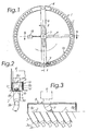
- Figure 2 is a detailed view of the nozzle seen in the direction of rotation
- Figure 3 is a detailed view of the nozzle looking towards the rotor axis
- Figure 4 is a cross-sectional view taken along the line A-A
- Figure 5 is a cross-sectional view taken along the line B-B.
- Figure 1 shows a round distributor housing 1 having outlet apertures 2, a central rotor shaft 5, a first rotor arm 6 with nozzle 7 and a second rotor arm 11.
- the distributor housing is seen from above.
- a cover will preferably be arranged on the distributor housing, as can be seen from Figures 4 and 5 .
- a preferred embodiment of the invention comprises a first rotor arm 6 and a second rotor arm 11.
- the second rotor arm 11 has at least one opening 12 for distributing solid particles in the outlet holes 2.
- the second rotor arm 11 preferably consists of a pipe that is angled relative to the rotor axis and which is bent at the opening 12 so as to lead the particles into the holes 2.
- a counterweight 13 may be arranged on the diagonally opposite side of the rotor axis relative to the second rotor arm 11, as shown in Figure 1 .
- This counterweight may be in the form of an additional hollow rotor arm in flow communication with the second supply pipe 10 and having an opening which is level with the outlet holes 2.
- Figures 2 and 3 show an embodiment of the invention wherein a U-shaped guard S is arranged around the nozzle 7.
- the distributor housing 1 is equipped with an annular channel 1a in the bottom 1b of which the outlet holes 2 are arranged.
- the annular channel 1a has side walls 1c, 1d.
- the nozzle 7 projects down into the annular channel 1a between the side walls 1c, 1d.
- the bottom 8a of the guard 8 faces upwards.
- the side walls 8b of the guard project down into the channel roughly parallel to the side walls 1c, 1d.
- the nozzle 7 is passed in through the guard 8.
- the guard 8 prevents or limits spray from the nozzle.
- the guard 8 may be equipped with end walls 8c, 8d and extend across several outlet holes 2.
- Figures 4 and 5 are cross-sectional views of the distributor seen from side from two different directions. From Figure 4 it can be seen how the hollow rotor shaft 5 is in flow communication with the first rotor arm 6, so that liquid can flow in through the first supply pipe 4, through the hollow rotor shaft 5, out into the first rotor arm 6 and out through the nozzle 7.
- Figure 5 shows how the hollow rotor shaft 5 is in flow communication with the second rotor arm 11, which means that solid particles can be passed in through the second supply pipe 10, through the hollow rotor 5, and out into the second rotor arm 11 and then out through the opening 12.
- Arranged in the hollow rotor shaft 5, between the two rotor arms 6, 11, is a dividing wall which ensures two separate streams until the liquid and the solid particles are mixed in the outlet pipes 3.
Landscapes
- Life Sciences & Earth Sciences (AREA)
- Soil Sciences (AREA)
- Environmental Sciences (AREA)
- Engineering & Computer Science (AREA)
- Water Supply & Treatment (AREA)
- Fertilizing (AREA)
- Sowing (AREA)
- Earth Drilling (AREA)
- Threshing Machine Elements (AREA)
- Input Circuits Of Receivers And Coupling Of Receivers And Audio Equipment (AREA)
- Medicines That Contain Protein Lipid Enzymes And Other Medicines (AREA)
- Enzymes And Modification Thereof (AREA)
- Vaporization, Distillation, Condensation, Sublimation, And Cold Traps (AREA)
- External Artificial Organs (AREA)
- Transition And Organic Metals Composition Catalysts For Addition Polymerization (AREA)
- Crystals, And After-Treatments Of Crystals (AREA)
- Catching Or Destruction (AREA)
- Crushing And Grinding (AREA)
Abstract
Description
- The present invention relates to a rotary distributor for spreading solid particles and/or a liquid. The invention also relates to a method for distributing solid particles by means of this rotary distributor.
- Rotary distributors for spreading liquid farmyard manure and similar liquids or suspensions are already known. Such apparatus are described in, e.g.,
DE 3703743 ,DE 4136162 andNO 172521 . The apparatus described consist of a circular distributor housing having a plurality of apertures arranged in a ring on the underside thereof. Arranged inside the distributor housing is a rotating pipe, the discharge opening of which, during use, moves across the apertures. The inlet opening of the pipe is connected to the hollow shaft of the housing for liquid communication. Thus, liquid is passed into the bottom, up through the shaft, out through the pipe and is spread out across the apertures. From the apertures, the liquid is passed out onto the field through hoses and optionally other equipment. - The known apparatus are used for the uniform distribution of liquid farmyard manure on the field. Sowing is done before or after the fertilising in a separate work process. An integration of these two separate work processes into one operation would be timesaving and cost-effective and would also provide environmental benefits.
-
Norwegian Patent 306091 - The object of the present invention is to provide a device for the simultaneous distribution of liquid fertiliser and seed corn or the like for use in a combined fertilising and sowing process.
- The subject of the present invention is a rotary distributor for use in spreading solid particles and/or liquid, comprising a round distributor housing having outlet holes arranged peripherally in the horizontal bottom of the housing and connected to outlet pipes, a first supply pipe arranged centrally in the bottom of the distributor housing for the supply of liquid under pressure and connected to a vertical, rotatably supported hollow rotor shaft in flow communication with a first transverse hollow rotor arm which has at least one angled, downward-directed nozzle that is level with the outlet holes, characterised in that the distributor housing comprises a second supply pipe arranged centrally in the top of the distributor housing for the supply of solid particles and/or liquid and connected to the vertical rotatably supported hollow rotor shaft in flow communication with a second transverse hollow rotor arm which has at least one downward-directed opening that is level with the outlet holes, and that the rotor shaft comprises a dividing wall between the two rotor arms which ensures two separate streams.
- The invention also comprises a method for distributing solid particles, characterised in that the solid particles are fed with a liquid under pressure or a gas stream to the second supply pipe in a distributor according to the invention and the rotor shaft is rotated, whereby the rotation and the liquid or gas cause the solid particles to be distributed evenly across the outlet holes and flow out through the outlet pipes.
- Other features of the invention are set forth in the dependent claims.
- The term "liquid" in the present application is used to mean water, an aqueous solution, liquid fertiliser, especially farmyard manure, a suspension, an emulsion or other substantially liquid substances which may contain, solids.
- The solid particles that can be distributed by the rotary distributor according to the invention comprise for example, seed corn, seeds, solid fertilisers, lime and other solid soil additives.
- The gas stream is according to the invention preferably an air stream.
- The distributor according to the invention can be used to provide a homogenous mixture of solid particles and a liquid whilst obtaining a uniform distribution of the mixture on the field.
- One advantage of the rotary distributor according to the invention is that sowing and fertilising can be carried out simultaneously. Thus, seeds are fed to the second supply pipe whilst liquid farmyard manure is supplied under pressure to the first supply pipe. When the liquid fertiliser flows out through the nozzle, the rotor shaft is set in motion. Thus, seeds and fertiliser are distributed evenly to the outlet holes. Hoses which pass the mixture formed onto the field may be connected to the outlet pipes. In this case, the mixture is either laid directly onto the soil, or a suitable device ensures that it is injected into the soil. Such injecting devices are known from the prior art.
- The invention involves a number of advantages, First, a work operation is saved because two processes are carried out simultaneously. This saves both time and fuel, which improves the farmer's finances and reduces the emission of greenhouse gases into the environment. Secondly, reduced soil cultivation through direct sowing causes a decrease in the loss of nitrogen through run-off and thus gives rise to better resource utilisation and less pollution. Tests also show a considerable reduction in erosion and a decrease in phosphorus pollution from areas which have been sown directly without soil cultivation. Thirdly, the investment costs in agricultural machines are reduced, as one machine carries out several work processes.
- The use of wet sowing technique gives the advantages of a more certain plant establishment, as seeds are mixed with a growth medium which gives both the necessary moisture for the seed to germinate and plant nutrition for growth. In conditions in which liquid farmyard manure is not available, water or another liquid can be used.
- The rotary distributor according to the invention may also be used for distributing dry particles such as seeds, artificial fertiliser and lime. By means of a gas stream, the particles are transported into the second supply pipe, out into the second rotor arm, out through the opening in the rotor arm and are distributed across the outlet apertures in that the rotor shaft is rotated mechanically. From the outlet pipes, the particles are carried by the gas stream onwards and downwards onto the ground or into the soil.
- The rotary distributor according to the invention may also be used for distributing two different liquids; for example, when adding a liquid supplement to the liquid farmyard manure. Thus, a second liquid stream is added to the second supply pipe and the liquid flows through the hollow shaft and out through the second rotor and out through the opening and into the outlet apertures.
- The rotary distributor according to the invention may also be used solely for distributing a liquid under pressure, that is to say without material being fed to the second supply pipe. Thus, it is not necessary for the user to invest in a separate distributor for the spreading of liquid.
- Within the scope of the present invention, the particles can be carried forward to and fed into the second supply pipe in any manner, for example, by means of an air stream, a mechanical conveyor or by using the force of gravity.
- The outlet pipes from the distributor housing are optionally connected via hoses to one or more devices which lead the mixture to where the user wishes to sow/water/fertilise.
- In use, the distributor may be a part of an agricultural machine. For example, the distributor can be connected to a spreader boom that is moved across a field by a tractor.
- The invention will now be described in more detail below with reference to the drawings which schematically show some possible embodiments of the invention.
-
Figure 1 is a top view of a distributor;
Figure 2 is a detailed view of the nozzle seen in the direction of rotation;
Figure 3 is a detailed view of the nozzle looking towards the rotor axis;
Figure 4 is a cross-sectional view taken along the line A-A; and
Figure 5 is a cross-sectional view taken along the line B-B. -
Figure 1 shows a round distributor housing 1 havingoutlet apertures 2, acentral rotor shaft 5, afirst rotor arm 6 withnozzle 7 and a second rotor arm 11. The distributor housing is seen from above. In use, a cover will preferably be arranged on the distributor housing, as can be seen fromFigures 4 and 5 . - As can be seen in
Figures 1 and5 , a preferred embodiment of the invention comprises afirst rotor arm 6 and a second rotor arm 11. The second rotor arm 11 has at least oneopening 12 for distributing solid particles in theoutlet holes 2. The second rotor arm 11 preferably consists of a pipe that is angled relative to the rotor axis and which is bent at theopening 12 so as to lead the particles into theholes 2. - A
counterweight 13 may be arranged on the diagonally opposite side of the rotor axis relative to the second rotor arm 11, as shown inFigure 1 . This counterweight may be in the form of an additional hollow rotor arm in flow communication with thesecond supply pipe 10 and having an opening which is level with theoutlet holes 2. -
Figures 2 and 3 show an embodiment of the invention wherein a U-shaped guard S is arranged around thenozzle 7. Furthermore, the distributor housing 1 is equipped with an annular channel 1a in the bottom 1b of which theoutlet holes 2 are arranged. The annular channel 1a has side walls 1c, 1d. Thenozzle 7 projects down into the annular channel 1a between the side walls 1c, 1d. The bottom 8a of theguard 8 faces upwards. Theside walls 8b of the guard project down into the channel roughly parallel to the side walls 1c, 1d. Thenozzle 7 is passed in through theguard 8. Theguard 8 prevents or limits spray from the nozzle. As shown inFigure 3 , theguard 8 may be equipped withend walls 8c, 8d and extend across several outlet holes 2. -
Figures 4 and 5 are cross-sectional views of the distributor seen from side from two different directions. FromFigure 4 it can be seen how thehollow rotor shaft 5 is in flow communication with thefirst rotor arm 6, so that liquid can flow in through thefirst supply pipe 4, through thehollow rotor shaft 5, out into thefirst rotor arm 6 and out through thenozzle 7.Figure 5 shows how thehollow rotor shaft 5 is in flow communication with the second rotor arm 11, which means that solid particles can be passed in through thesecond supply pipe 10, through thehollow rotor 5, and out into the second rotor arm 11 and then out through theopening 12. Arranged in thehollow rotor shaft 5, between the tworotor arms 6, 11, is a dividing wall which ensures two separate streams until the liquid and the solid particles are mixed in theoutlet pipes 3.
Claims (6)
- A rotary distributor for use in spreading solid particles and/or liquid, comprising a round distributor housing (1), having outlet holes (2) arranged peripherally in the horizontal bottom of the housing and connected to outlet pipes (3), a first supply pipe (4) arranged centrally in the bottom of the distributor housing (1) for the supply of liquid under pressure and connected to a vertical, rotatably supported hollow rotor shaft (5) in flow communication with a first transverse hollow rotor arm (6) which has at least one angled, downward-directed nozzle (7) that is level with the outlet holes (2),
characterised in that the distributor housing (1) comprises a second supply pipe (10) arranged centrally in the top of the distributor housing (1) for the supply of solid particles and/or liquid and connected to the vertical, rotatably supported hollow rotor shaft (5), in flow communication with a second transverse hollow rotor arm (11) which has at least one downward-directed opening (12) that is level with the outlet holes (2), and that the rotor shaft (5) comprises a dividing wall between the two rotor arms (6) and (11) which ensures two separate streams. - A rotary distributor according to claim 1,
characterised in that a counterweight (13) is provided on the diagonally opposite side of the rotor axis relative to the second rotor arm (11). - A rotary distributor according to claim 2,
characterised in that the counterweight (13) is made in the form of a third rotor arm in flow communication with the second supply pipe (10) and the hollow rotor shaft (5), and which is equipped with at least one downward-directed opening which is level with the outlet holes (2). - A rotary distributor according to any one of claims 1-3, characterised in that the distributor housing (1) further comprises an upwardly open annular channel (1a) with bottom (1b) and outer and inner side walls (1c, 1d), in the bottom (1b) of which the outlet holes (2) are equidistantly arranged, and between whose side walls (1c, 1d) the nozzle/nozzles (7) and the opening (12) project down, each nozzle (7) being surrounded by and connected to a guard (8) having a U-shaped cross-section with its bottom (8a) uppermost, and side walls (8b) which project into the ring channel (1a) on either side of the nozzle (7).
- A method for distributing solid particles,
characterised in that the method comprises the steps of- feeding the solid particles with a liquid under pressure or a gas stream to a second supply pipe (10) in a distributor according to claim 1 and- rotating the rotor shaft (5),- whereby the rotation and the liquid or gas cause the solid particles to be distributed evenly over the outlet holes (2) and flow out through the outlet pipes (3). - A method according to claim 5, characterised by feeding to said second supply pipe (10), with liquid under pressure or a gas stream, solid particles in the form of seeds, solid fertilisers, lime and other solid soil additives.
Applications Claiming Priority (3)
| Application Number | Priority Date | Filing Date | Title |
|---|---|---|---|
| NO20021854 | 2002-04-19 | ||
| NO20021854A NO316421B1 (en) | 2002-04-19 | 2002-04-19 | Rotary distributor, method of its use and use of the distributor |
| PCT/NO2003/000122 WO2003088735A1 (en) | 2002-04-19 | 2003-04-14 | Rotary distributor, methods for its use and the use of the distributor |
Publications (2)
| Publication Number | Publication Date |
|---|---|
| EP1519647A1 EP1519647A1 (en) | 2005-04-06 |
| EP1519647B1 true EP1519647B1 (en) | 2008-02-13 |
Family
ID=19913540
Family Applications (1)
| Application Number | Title | Priority Date | Filing Date |
|---|---|---|---|
| EP03725889A Expired - Lifetime EP1519647B1 (en) | 2002-04-19 | 2003-04-14 | Rotary distributor, methods for its use and the use of the distributor |
Country Status (11)
| Country | Link |
|---|---|
| US (1) | US7318557B2 (en) |
| EP (1) | EP1519647B1 (en) |
| AT (1) | ATE385670T1 (en) |
| AU (1) | AU2003228148A1 (en) |
| CA (1) | CA2482954C (en) |
| DE (1) | DE60319085T2 (en) |
| DK (1) | DK1519647T3 (en) |
| ES (1) | ES2300577T3 (en) |
| NO (1) | NO316421B1 (en) |
| PL (1) | PL216204B1 (en) |
| WO (1) | WO2003088735A1 (en) |
Families Citing this family (1)
| Publication number | Priority date | Publication date | Assignee | Title |
|---|---|---|---|---|
| WO2021155008A1 (en) * | 2020-01-29 | 2021-08-05 | Brooklyn Bridge To Cambodia, Inc. | Seed metering apparatus and methods of operation |
Family Cites Families (21)
| Publication number | Priority date | Publication date | Assignee | Title |
|---|---|---|---|---|
| US2601534A (en) * | 1952-06-24 | Distributor | ||
| US1348885A (en) * | 1918-10-12 | 1920-08-10 | James F Laffoon | Proportional distributer |
| US1443342A (en) * | 1920-01-27 | 1923-01-30 | Cabrini Attilio | Apparatus for sowing rice |
| GB1045732A (en) * | 1962-05-09 | 1966-10-19 | Nat Res Dev | Improvements relating to the sowing of seeds |
| FR1573370A (en) * | 1967-06-30 | 1969-07-04 | ||
| US4489892A (en) * | 1982-05-06 | 1984-12-25 | Lor-Al Corporation | Apparatus for distributing a substance |
| CA1202527A (en) * | 1982-11-09 | 1986-04-01 | Eric W. Fuss | Air seeder distributor |
| DE3417372A1 (en) * | 1984-05-10 | 1985-11-14 | Josef Eckart & Söhne, 8300 Landshut | Method and device for discharging liquid material, in particular liquid manure, from vehicles |
| DE3703743A1 (en) * | 1986-02-13 | 1987-08-20 | Karl Stade | Drag-hose liquid-manure distributor |
| US4913244A (en) * | 1986-09-11 | 1990-04-03 | Eastman Christensen Company | Large compact cutter rotary drill bit utilizing directed hydraulics for each cutter |
| NO172521C (en) | 1991-04-19 | 1993-08-04 | Kjell Vastveit | ROTATING LIQUID BENEFITS FOR USE WITH FLUID FERTILIZER SPREADER, WATER OR OTHER LIQUID ADDED WITH OTHER SUBSTANCES |
| GB9113736D0 (en) * | 1991-06-26 | 1991-08-14 | Greentrac Ltd | Improvements in or relating to injection apparatus for injecting slurry into the ground |
| DE4136162C1 (en) | 1991-11-02 | 1992-09-10 | Karl 4409 Havixbeck De Stade | Distributor attached to mobile slurry containers - has central pipe passing slurry into rotatable disc-shaped head |
| US5271567A (en) * | 1992-08-26 | 1993-12-21 | Ag-Chem Equipment Co., Inc. | Fertilizer distribution head and dispensing chute |
| DE4241176B4 (en) * | 1992-12-08 | 2005-12-22 | Focke & Co.(Gmbh & Co. Kg) | Apparatus for applying glue to blanks for folding boxes |
| NO306091B1 (en) * | 1997-10-31 | 1999-09-20 | Forskningsparken I & S As | Method of fluid implantation in growth medium |
| NL1011803C2 (en) * | 1999-04-15 | 2000-10-17 | Veenhuis Machines | Device and working method for fertilizing land. |
| US6557573B2 (en) * | 2001-02-06 | 2003-05-06 | Pgi International, Ltd. | Liquid fertilizer distribution system and method |
| US20020121382A1 (en) * | 2001-03-02 | 2002-09-05 | Fima Raoul G. | Lighter-than-air water dispensing airship for fire control |
| US6997400B1 (en) * | 2002-07-17 | 2006-02-14 | Iowa State University Research Foundation, Inc. | Apparatus and method for reducing anhydrous ammonia application by optimizing distribution |
| DK176393B1 (en) * | 2005-03-17 | 2007-11-12 | Samson Agro As | Manure distributor for manure distribution boom and method for controlling spread width for a manure distribution boom |
-
2002
- 2002-04-19 NO NO20021854A patent/NO316421B1/en not_active IP Right Cessation
-
2003
- 2003-04-14 AU AU2003228148A patent/AU2003228148A1/en not_active Abandoned
- 2003-04-14 DK DK03725889T patent/DK1519647T3/en active
- 2003-04-14 ES ES03725889T patent/ES2300577T3/en not_active Expired - Lifetime
- 2003-04-14 EP EP03725889A patent/EP1519647B1/en not_active Expired - Lifetime
- 2003-04-14 DE DE60319085T patent/DE60319085T2/en not_active Expired - Lifetime
- 2003-04-14 AT AT03725889T patent/ATE385670T1/en active
- 2003-04-14 PL PL373040A patent/PL216204B1/en unknown
- 2003-04-14 WO PCT/NO2003/000122 patent/WO2003088735A1/en active IP Right Grant
- 2003-04-14 CA CA2482954A patent/CA2482954C/en not_active Expired - Fee Related
- 2003-04-14 US US10/511,879 patent/US7318557B2/en not_active Expired - Lifetime
Also Published As
| Publication number | Publication date |
|---|---|
| NO20021854D0 (en) | 2002-04-19 |
| CA2482954C (en) | 2010-06-15 |
| DE60319085T2 (en) | 2009-01-29 |
| PL373040A1 (en) | 2005-08-08 |
| NO316421B1 (en) | 2004-01-26 |
| DK1519647T3 (en) | 2008-06-02 |
| NO20021854L (en) | 2003-10-20 |
| US7318557B2 (en) | 2008-01-15 |
| ES2300577T3 (en) | 2008-06-16 |
| EP1519647A1 (en) | 2005-04-06 |
| ATE385670T1 (en) | 2008-03-15 |
| US20050167525A1 (en) | 2005-08-04 |
| DE60319085D1 (en) | 2008-03-27 |
| AU2003228148A1 (en) | 2003-11-03 |
| PL216204B1 (en) | 2014-03-31 |
| CA2482954A1 (en) | 2003-10-30 |
| WO2003088735A1 (en) | 2003-10-30 |
Similar Documents
| Publication | Publication Date | Title |
|---|---|---|
| EP0061335B1 (en) | Pneumatic granular or seed applicator | |
| US20180343792A1 (en) | Horizontal Rotary Product Distributor For Granular Fertilizer Application System | |
| US8104648B2 (en) | Mixing applicator | |
| DE69206332D1 (en) | Improvements to devices for introducing liquid manure or other liquids into the soil. | |
| US4300461A (en) | Grass seed planter having fluid injection soil opener | |
| US4202283A (en) | Process and apparatus for distributing cold ammonia | |
| EP1519647B1 (en) | Rotary distributor, methods for its use and the use of the distributor | |
| CN213866014U (en) | Fertilizer coating machine | |
| AU723527B2 (en) | Application of coatings to seeds, etc. | |
| ES483154A1 (en) | Apparatus for distributing pulverized or granular material, notably for a sowing machine or an agricultural spreader. | |
| JPH0851877A (en) | Additional manure applicator for tree planted in field | |
| EP0580712B1 (en) | Rotating liquid distributor for use with a spreader for liquid manure, water or other liquids with other compounds added | |
| JP2716084B2 (en) | Fertilizer sowing equipment | |
| JPH0675443B2 (en) | Powder / granular substance spraying device | |
| RU2227974C1 (en) | Plant for preparation and application of fertilizer solution with irrigation water in drop irrigation systems | |
| JP3696167B2 (en) | Adjusted mixing and distribution method for wood chips and multi-materials | |
| JP3666802B2 (en) | Base material spreading machine and its spreading method | |
| JP3052128U (en) | Compost spreader | |
| RU2272393C1 (en) | Apparatus for subsurface application of liquid fertilizers | |
| SU1727631A1 (en) | Mixer-distributor for liquid fertilizer and gases | |
| JPH104720A (en) | Forming, dusting or seeding of material for field and apparatus therefor | |
| CN114009202A (en) | Flowers liquid manure integration irrigation equipment | |
| KR200141816Y1 (en) | Distributer | |
| HU180964B (en) | Method and apparatus for deep fertilizing | |
| JPH06153643A (en) | Spraying or sowing of granular material and apparatus therefor |
Legal Events
| Date | Code | Title | Description |
|---|---|---|---|
| PUAI | Public reference made under article 153(3) epc to a published international application that has entered the european phase |
Free format text: ORIGINAL CODE: 0009012 |
|
| 17P | Request for examination filed |
Effective date: 20041109 |
|
| AK | Designated contracting states |
Kind code of ref document: A1 Designated state(s): AT BE BG CH CY CZ DE DK EE ES FI FR GB GR HU IE IT LI LU MC NL PT RO SE SI SK TR |
|
| AX | Request for extension of the european patent |
Extension state: AL LT LV MK |
|
| 17Q | First examination report despatched |
Effective date: 20061121 |
|
| GRAP | Despatch of communication of intention to grant a patent |
Free format text: ORIGINAL CODE: EPIDOSNIGR1 |
|
| RIC1 | Information provided on ipc code assigned before grant |
Ipc: A01C 23/00 20060101ALI20070720BHEP Ipc: A01C 5/08 20060101AFI20070720BHEP |
|
| RIN1 | Information on inventor provided before grant (corrected) |
Inventor name: VASTVEIT, KJELL |
|
| GRAS | Grant fee paid |
Free format text: ORIGINAL CODE: EPIDOSNIGR3 |
|
| GRAA | (expected) grant |
Free format text: ORIGINAL CODE: 0009210 |
|
| AK | Designated contracting states |
Kind code of ref document: B1 Designated state(s): AT BE BG CH CY CZ DE DK EE ES FI FR GB GR HU IE IT LI LU MC NL PT RO SE SI SK TR |
|
| AX | Request for extension of the european patent |
Extension state: AL LT LV MK |
|
| REG | Reference to a national code |
Ref country code: GB Ref legal event code: FG4D |
|
| REG | Reference to a national code |
Ref country code: CH Ref legal event code: EP |
|
| REG | Reference to a national code |
Ref country code: IE Ref legal event code: FG4D |
|
| REF | Corresponds to: |
Ref document number: 60319085 Country of ref document: DE Date of ref document: 20080327 Kind code of ref document: P |
|
| REG | Reference to a national code |
Ref country code: DK Ref legal event code: T3 |
|
| REG | Reference to a national code |
Ref country code: SE Ref legal event code: TRGR |
|
| REG | Reference to a national code |
Ref country code: ES Ref legal event code: FG2A Ref document number: 2300577 Country of ref document: ES Kind code of ref document: T3 |
|
| PG25 | Lapsed in a contracting state [announced via postgrant information from national office to epo] |
Ref country code: SI Free format text: LAPSE BECAUSE OF FAILURE TO SUBMIT A TRANSLATION OF THE DESCRIPTION OR TO PAY THE FEE WITHIN THE PRESCRIBED TIME-LIMIT Effective date: 20080213 Ref country code: BE Free format text: LAPSE BECAUSE OF FAILURE TO SUBMIT A TRANSLATION OF THE DESCRIPTION OR TO PAY THE FEE WITHIN THE PRESCRIBED TIME-LIMIT Effective date: 20080213 |
|
| ET | Fr: translation filed | ||
| PG25 | Lapsed in a contracting state [announced via postgrant information from national office to epo] |
Ref country code: PT Free format text: LAPSE BECAUSE OF FAILURE TO SUBMIT A TRANSLATION OF THE DESCRIPTION OR TO PAY THE FEE WITHIN THE PRESCRIBED TIME-LIMIT Effective date: 20080714 Ref country code: SK Free format text: LAPSE BECAUSE OF FAILURE TO SUBMIT A TRANSLATION OF THE DESCRIPTION OR TO PAY THE FEE WITHIN THE PRESCRIBED TIME-LIMIT Effective date: 20080213 |
|
| PG25 | Lapsed in a contracting state [announced via postgrant information from national office to epo] |
Ref country code: RO Free format text: LAPSE BECAUSE OF FAILURE TO SUBMIT A TRANSLATION OF THE DESCRIPTION OR TO PAY THE FEE WITHIN THE PRESCRIBED TIME-LIMIT Effective date: 20080213 Ref country code: MC Free format text: LAPSE BECAUSE OF NON-PAYMENT OF DUE FEES Effective date: 20080430 |
|
| REG | Reference to a national code |
Ref country code: CH Ref legal event code: PL |
|
| PLBE | No opposition filed within time limit |
Free format text: ORIGINAL CODE: 0009261 |
|
| STAA | Information on the status of an ep patent application or granted ep patent |
Free format text: STATUS: NO OPPOSITION FILED WITHIN TIME LIMIT |
|
| 26N | No opposition filed |
Effective date: 20081114 |
|
| PG25 | Lapsed in a contracting state [announced via postgrant information from national office to epo] |
Ref country code: LI Free format text: LAPSE BECAUSE OF NON-PAYMENT OF DUE FEES Effective date: 20080430 Ref country code: EE Free format text: LAPSE BECAUSE OF FAILURE TO SUBMIT A TRANSLATION OF THE DESCRIPTION OR TO PAY THE FEE WITHIN THE PRESCRIBED TIME-LIMIT Effective date: 20080213 Ref country code: CH Free format text: LAPSE BECAUSE OF NON-PAYMENT OF DUE FEES Effective date: 20080430 |
|
| PG25 | Lapsed in a contracting state [announced via postgrant information from national office to epo] |
Ref country code: BG Free format text: LAPSE BECAUSE OF FAILURE TO SUBMIT A TRANSLATION OF THE DESCRIPTION OR TO PAY THE FEE WITHIN THE PRESCRIBED TIME-LIMIT Effective date: 20080513 |
|
| PG25 | Lapsed in a contracting state [announced via postgrant information from national office to epo] |
Ref country code: CY Free format text: LAPSE BECAUSE OF FAILURE TO SUBMIT A TRANSLATION OF THE DESCRIPTION OR TO PAY THE FEE WITHIN THE PRESCRIBED TIME-LIMIT Effective date: 20080213 |
|
| PG25 | Lapsed in a contracting state [announced via postgrant information from national office to epo] |
Ref country code: IT Free format text: LAPSE BECAUSE OF NON-PAYMENT OF DUE FEES Effective date: 20080414 |
|
| PGFP | Annual fee paid to national office [announced via postgrant information from national office to epo] |
Ref country code: CZ Payment date: 20100310 Year of fee payment: 8 |
|
| PG25 | Lapsed in a contracting state [announced via postgrant information from national office to epo] |
Ref country code: LU Free format text: LAPSE BECAUSE OF NON-PAYMENT OF DUE FEES Effective date: 20080414 Ref country code: HU Free format text: LAPSE BECAUSE OF FAILURE TO SUBMIT A TRANSLATION OF THE DESCRIPTION OR TO PAY THE FEE WITHIN THE PRESCRIBED TIME-LIMIT Effective date: 20080814 |
|
| PG25 | Lapsed in a contracting state [announced via postgrant information from national office to epo] |
Ref country code: TR Free format text: LAPSE BECAUSE OF FAILURE TO SUBMIT A TRANSLATION OF THE DESCRIPTION OR TO PAY THE FEE WITHIN THE PRESCRIBED TIME-LIMIT Effective date: 20080213 |
|
| PG25 | Lapsed in a contracting state [announced via postgrant information from national office to epo] |
Ref country code: GR Free format text: LAPSE BECAUSE OF NON-PAYMENT OF DUE FEES Effective date: 20080430 |
|
| PGRI | Patent reinstated in contracting state [announced from national office to epo] |
Ref country code: IT Effective date: 20110616 |
|
| PG25 | Lapsed in a contracting state [announced via postgrant information from national office to epo] |
Ref country code: CZ Free format text: LAPSE BECAUSE OF NON-PAYMENT OF DUE FEES Effective date: 20110414 |
|
| REG | Reference to a national code |
Ref country code: FR Ref legal event code: PLFP Year of fee payment: 14 |
|
| REG | Reference to a national code |
Ref country code: FR Ref legal event code: PLFP Year of fee payment: 15 |
|
| REG | Reference to a national code |
Ref country code: FR Ref legal event code: PLFP Year of fee payment: 16 |
|
| PGFP | Annual fee paid to national office [announced via postgrant information from national office to epo] |
Ref country code: IE Payment date: 20220331 Year of fee payment: 20 Ref country code: GB Payment date: 20220323 Year of fee payment: 20 Ref country code: DK Payment date: 20220323 Year of fee payment: 20 |
|
| PGFP | Annual fee paid to national office [announced via postgrant information from national office to epo] |
Ref country code: SE Payment date: 20220323 Year of fee payment: 20 Ref country code: IT Payment date: 20220217 Year of fee payment: 20 Ref country code: FR Payment date: 20220323 Year of fee payment: 20 |
|
| PGFP | Annual fee paid to national office [announced via postgrant information from national office to epo] |
Ref country code: NL Payment date: 20220420 Year of fee payment: 20 |
|
| PGFP | Annual fee paid to national office [announced via postgrant information from national office to epo] |
Ref country code: ES Payment date: 20220615 Year of fee payment: 20 Ref country code: DE Payment date: 20220401 Year of fee payment: 20 |
|
| PGFP | Annual fee paid to national office [announced via postgrant information from national office to epo] |
Ref country code: FI Payment date: 20220419 Year of fee payment: 20 Ref country code: AT Payment date: 20220427 Year of fee payment: 20 |
|
| REG | Reference to a national code |
Ref country code: DE Ref legal event code: R071 Ref document number: 60319085 Country of ref document: DE |
|
| REG | Reference to a national code |
Ref country code: DK Ref legal event code: EUP Expiry date: 20230414 |
|
| REG | Reference to a national code |
Ref country code: NL Ref legal event code: MK Effective date: 20230413 |
|
| REG | Reference to a national code |
Ref country code: GB Ref legal event code: PE20 Expiry date: 20230413 Ref country code: ES Ref legal event code: FD2A Effective date: 20230503 |
|
| REG | Reference to a national code |
Ref country code: IE Ref legal event code: MK9A |
|
| REG | Reference to a national code |
Ref country code: SE Ref legal event code: EUG |
|
| REG | Reference to a national code |
Ref country code: AT Ref legal event code: MK07 Ref document number: 385670 Country of ref document: AT Kind code of ref document: T Effective date: 20230414 |
|
| PG25 | Lapsed in a contracting state [announced via postgrant information from national office to epo] |
Ref country code: IE Free format text: LAPSE BECAUSE OF EXPIRATION OF PROTECTION Effective date: 20230414 Ref country code: ES Free format text: LAPSE BECAUSE OF EXPIRATION OF PROTECTION Effective date: 20230415 |
|
| PG25 | Lapsed in a contracting state [announced via postgrant information from national office to epo] |
Ref country code: GB Free format text: LAPSE BECAUSE OF EXPIRATION OF PROTECTION Effective date: 20230413 |