EP1519635A1 - Beleuchtungssystem mit einer Mikrowelle niedriger Ausgangsleistung und Verfahren zur Reduzierung des Flimmerns dafür - Google Patents
Beleuchtungssystem mit einer Mikrowelle niedriger Ausgangsleistung und Verfahren zur Reduzierung des Flimmerns dafür Download PDFInfo
- Publication number
- EP1519635A1 EP1519635A1 EP04002019A EP04002019A EP1519635A1 EP 1519635 A1 EP1519635 A1 EP 1519635A1 EP 04002019 A EP04002019 A EP 04002019A EP 04002019 A EP04002019 A EP 04002019A EP 1519635 A1 EP1519635 A1 EP 1519635A1
- Authority
- EP
- European Patent Office
- Prior art keywords
- voltage
- power factor
- outputting
- unit
- frequency
- Prior art date
- Legal status (The legal status is an assumption and is not a legal conclusion. Google has not performed a legal analysis and makes no representation as to the accuracy of the status listed.)
- Withdrawn
Links
- 238000000034 method Methods 0.000 title claims description 8
- 230000001965 increasing effect Effects 0.000 claims description 5
- 238000009499 grossing Methods 0.000 claims description 4
- 230000006872 improvement Effects 0.000 claims description 2
- 230000001131 transforming effect Effects 0.000 claims description 2
- 238000001816 cooling Methods 0.000 description 13
- 238000010586 diagram Methods 0.000 description 8
- 238000010276 construction Methods 0.000 description 6
- 230000002708 enhancing effect Effects 0.000 description 2
- 239000004065 semiconductor Substances 0.000 description 2
- 230000015556 catabolic process Effects 0.000 description 1
- 230000008859 change Effects 0.000 description 1
- 239000012141 concentrate Substances 0.000 description 1
- 230000008878 coupling Effects 0.000 description 1
- 238000010168 coupling process Methods 0.000 description 1
- 238000005859 coupling reaction Methods 0.000 description 1
- 238000006731 degradation reaction Methods 0.000 description 1
- 230000002500 effect on skin Effects 0.000 description 1
- 238000010438 heat treatment Methods 0.000 description 1
- 230000004048 modification Effects 0.000 description 1
- 238000012986 modification Methods 0.000 description 1
Images




Classifications
-
- H—ELECTRICITY
- H05—ELECTRIC TECHNIQUES NOT OTHERWISE PROVIDED FOR
- H05B—ELECTRIC HEATING; ELECTRIC LIGHT SOURCES NOT OTHERWISE PROVIDED FOR; CIRCUIT ARRANGEMENTS FOR ELECTRIC LIGHT SOURCES, IN GENERAL
- H05B41/00—Circuit arrangements or apparatus for igniting or operating discharge lamps
- H05B41/14—Circuit arrangements
- H05B41/26—Circuit arrangements in which the lamp is fed by power derived from DC by means of a converter, e.g. by high-voltage DC
- H05B41/28—Circuit arrangements in which the lamp is fed by power derived from DC by means of a converter, e.g. by high-voltage DC using static converters
- H05B41/282—Circuit arrangements in which the lamp is fed by power derived from DC by means of a converter, e.g. by high-voltage DC using static converters with semiconductor devices
-
- H—ELECTRICITY
- H05—ELECTRIC TECHNIQUES NOT OTHERWISE PROVIDED FOR
- H05B—ELECTRIC HEATING; ELECTRIC LIGHT SOURCES NOT OTHERWISE PROVIDED FOR; CIRCUIT ARRANGEMENTS FOR ELECTRIC LIGHT SOURCES, IN GENERAL
- H05B41/00—Circuit arrangements or apparatus for igniting or operating discharge lamps
- H05B41/14—Circuit arrangements
- H05B41/26—Circuit arrangements in which the lamp is fed by power derived from DC by means of a converter, e.g. by high-voltage DC
- H05B41/28—Circuit arrangements in which the lamp is fed by power derived from DC by means of a converter, e.g. by high-voltage DC using static converters
- H05B41/2806—Circuit arrangements in which the lamp is fed by power derived from DC by means of a converter, e.g. by high-voltage DC using static converters with semiconductor devices and specially adapted for lamps without electrodes in the vessel, e.g. surface discharge lamps, electrodeless discharge lamps
- H05B41/2813—Arrangements for protecting lamps or circuits against abnormal operating conditions
-
- H—ELECTRICITY
- H05—ELECTRIC TECHNIQUES NOT OTHERWISE PROVIDED FOR
- H05B—ELECTRIC HEATING; ELECTRIC LIGHT SOURCES NOT OTHERWISE PROVIDED FOR; CIRCUIT ARRANGEMENTS FOR ELECTRIC LIGHT SOURCES, IN GENERAL
- H05B41/00—Circuit arrangements or apparatus for igniting or operating discharge lamps
- H05B41/14—Circuit arrangements
- H05B41/24—Circuit arrangements in which the lamp is fed by high frequency AC, or with separate oscillator frequency
-
- Y—GENERAL TAGGING OF NEW TECHNOLOGICAL DEVELOPMENTS; GENERAL TAGGING OF CROSS-SECTIONAL TECHNOLOGIES SPANNING OVER SEVERAL SECTIONS OF THE IPC; TECHNICAL SUBJECTS COVERED BY FORMER USPC CROSS-REFERENCE ART COLLECTIONS [XRACs] AND DIGESTS
- Y02—TECHNOLOGIES OR APPLICATIONS FOR MITIGATION OR ADAPTATION AGAINST CLIMATE CHANGE
- Y02B—CLIMATE CHANGE MITIGATION TECHNOLOGIES RELATED TO BUILDINGS, e.g. HOUSING, HOUSE APPLIANCES OR RELATED END-USER APPLICATIONS
- Y02B20/00—Energy efficient lighting technologies, e.g. halogen lamps or gas discharge lamps
Definitions
- the present invention relates to a microwave lighting system and, more particularly, to a low-output microwave lighting system capable of enhancing a stability of a system by removing a flicker phenomenon generated at a low output and a flicker removing method using the same.
- Figure 1 is a schematic block diagram showing a construction of a conventional lighting system using microwave.
- a lighting system using microwave includes: a magnetron 10 generating microwave; a resonator 30 having an electrodeless bulb 20 therein, resonating microwave supplied from the magnetron 10, and having a mesh form so that when the bulb converts microwave energy into light, the converted light can be discharged outwardly to its maximum; a wave guide 40 for guiding microwave generated from the magnetron 10 to the resonator 30; a high level voltage generator 50 for receiving power from an external source, boosting it to a high level voltage and supplying the high level voltage to the magnetron 10; a cooling unit 70 for cooling the magnetron 10 and the high level voltage generator 50 in order to prevent overheat of them due to a self-generated heat; a controller 60 for controlling the high level voltage generator 50 which applies the high level voltage to the magnetron and controlling an operation of the cooling unit 70; and a cooling completion memory unit 80 for memorizing whether cooling has been completed.
- the high level voltage generator 50 receives a drive signal outputted from the controller 60, increases AC power inputted from an external source, and supplies AC power of the increased high level voltage to the magnetron 10.
- the magnetron 10 is oscillated by the high level voltage outputted from the high level voltage generator 50 and concentrates microwave with a very high frequency to the electrodeless bulb 20 in the resonator 30 through the wave guide 40. Accordingly, the electrodeless bulb 20 absorbs the microwave energy to generate light.
- the controller 60 drives the cooling unit 70 to cool the high level voltage generator 50, the magnetron 10 and the electrodeless bulb 20, in order to prevent the high level voltage generator 50 and the magnetron 10 from being overheated due to self-heating.
- the electrodeless bulb 20 In order to actuate the lamp in an OFF state, the electrodeless bulb 20 should be sufficiently cooled for re-lighting the lamp.
- the cooling unit 70 is operated for a predetermined time to sufficiently cool the electrodeless bulb 20, a cooling completion state is recorded in the cooling completion memory unit 80, and then, the driving of the cooling unit 70 is stopped.
- the controller 60 reads the content of the cooling completion memory unit 80, and if the cooling has been completed, the controller 60 re-actuates the lamp, or otherwise, the controller drives the cooling unit 70 for a predetermined time, and then, re-actuates the lamp.
- the afore-mentioned microwave lighting system uses a linear high level voltage transformer in order to drive the magnetron.
- Figure 2 is a circuit diagram of the high level voltage generator using the linear high level voltage transformer in accordance with the conventional art
- Figure 3. is an exemplary view showing an output waveform of the conventional microwave lighting system.
- the electrodeless bulb is lighted by a secondary voltage generated by a voltage applied to a primary side of the linear high level voltage transformer.
- a power factor is degraded to increase a noise and a load of a circuit, resulting in degradation of stability of a system.
- an object of the present invention is to provide a low-output microwave lighting system capable of enhancing a stability of a system by removing a flicker phenomenon generated at a low output by using a power factor compensation circuit and an inverter-purpose transformer, and a flicker removing method using the same.
- a low-output microwave lighting system including: a rectifier for rectifying general AC power inputted through a power source unit and outputting a DC voltage; a power factor compensator for compensating a power factor of the DC voltage inputted through the rectifier; and an inverter circuit unit for receiving the power factor-compensated DC voltage and outputting an AC voltage through frequency varying.
- a flicker removing method using a low-noise microwave lighting system including: rectifying general AC power and outputting a DC voltage; increasing the DC voltage through a PFC circuit for improvement of a power factor to reduce a ripple; receiving the DC voltage, varying a frequency of the DC voltage through a half-bridge, and outputting an AC voltage; and receiving the AC voltage and driving a magnetron.
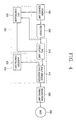
- FIG. 4 is a block diagram showing a construction of a microwave lighting system in accordance with the present invention.
- a low-output microwave lighting system of the present invention includes: a rectifier 200 for rectifying general AC power inputted through a power source unit 100 and outputting a DC voltage; a power factor compensator 300 for compensating a power factor of the DC voltage inputted through the rectifier 200; an inverter circuit unit 410 for receiving the power factor-compensated DC voltage and outputting an AC voltage through frequency varying; a magnetron driving unit 500 for transforming the AC voltage inputted from the inverter circuit unit 410 and generating a magnetron filament current and a high level voltage; and a magnetron 600 lighted by the high level voltage and current outputted from the magnetron driving unit 500.
- the power factor compensator 300 includes a PFC controller 320 for outputting a control signal for a power factor compensation by the rectified signal inputted through the rectifier 200; and a PFC circuit unit 310 for compensating the power factor of the DC voltage inputted through the rectifier 200 upon receiving the control signal.
- the inverter circuit unit 400 includes a half-bridge type inverter 410 for receiving the DC voltage outputted from the power factor compensator 300, varying its frequency, and outputting a corresponding AC voltage; and an inverter driving unit 420 for outputting a switching control signal to control switching of the half-bridge type inverter 410.
- FIG. 5 is a circuit diagram of the microwave lighting system in accordance with the present invention.
- microwave lighting system including the power factor compensator 300 and the inverter circuit unit 400 will now be described with reference to Figure 5.
- the power factor compensator 300 includes a coil L1, a rectifying diode D1 and a smoothing condenser C2 for converting the rectified DC voltage into a PFC output voltage; a feedback detector 340 for distributing the PFC output voltage to two resistances R2 and R3 and outputting a feedback voltage; a PFC controller 320 for receiving the feedback voltage from a contact point of the two resistances R2 and R3 and outputting a control signal for adjusting a power factor of the PFC output voltage; and a MISFET unit 330 having a gate terminal for receiving the control signal outputted from the PFC controller 320 and performing ON/OFF, and a drain terminal connected to a contact point of the coil L1 and the rectifying diode D1.
- the circuit is constructed such that a feedback voltage is set to be different according to the inputted DC voltage, a different control signal can be applied to the MOSFET unit according the PFC controller. Accordingly, the power factor compensator 310 can output various PFC output voltages.
- the inverter circuit unit 400 includes the half-bridge type inverter 410 having two MOSFETs each having a diode between a drain and a source; and an inverter driving unit 420 for outputting a switching control signal for controlling switching of the half-bridge type inverter unit 410.
- the half-bridge type inverter 410 includes two MOSFETs, that is, the switching units, of Q2 and Q3, and in this respect, since the diode is inserted between the drain and the source of the MOSFET, there are four power semiconductor switches. Accordingly, a form of an AC output voltage is determined according to a control method of Q2 and Q3 of the MOSFET.
- the rectifier 200 rectifies general AC power inputted through the power source unit 100 and applies a corresponding DC voltage to the PFC circuit unit 310.
- the rectified DC voltage is applied to the MOSFET unit 330 and the rectifying diode D1 through the coil L1 of the PFC circuit unit 310. Accordingly, output power of the rectifying diode D1 is smoothed by the smoothing condenser C2 and converted into a DC output voltage (Vout), that is, a PFC output voltage.
- Vout DC output voltage
- the PFC controller 320 applies a control signal for compensating a power factor of the DC voltage by the rectified signal inputted through the rectifier 200, to the MOSFET unit 330 of the PFC circuit unit 310.
- the MOSFET unit 330 if the MOSFET unit 330 is in an ON state, the energy of the input DC voltage is accumulated at the coil L1, whereas if the MOSFET unit 4 is in an OFF state, the energy accumulated at the coil L1 overlaps with the input DC voltage, rectified by the rectifying diode D1 and outputted as a DC output voltage by the smoothing condenser C2. Thus, a higher level DC output voltage than the input DC voltage can be obtained.
- the PFC circuit unit 310 applies a power factor-compensated high level DC output voltage to the half-bridge type inverter 410.
- the half-bridge type inverter 410 Upon receiving the DC voltage from the PFC circuit unit 310, the half-bridge type inverter 410 varies its frequency and a corresponding AC voltage. That is, in order to supply a waveform obtained by adding a sinusoidal high frequency component of a high frequency band to a square wave low frequency, to the lamp, the half-bridge type inverter 410 generates an AC output voltage from the PFC output voltage by a switching control signal of the inverter driving unit 420, and supplies it to the magnetron driving unit 500.
- the half-bridge type inverter shares the role of coupling and resonating or a role before and after lighting, and is driven at a frequency of 20 KHz or higher to remove a ripple.
- the magnetron driving unit 500 transforms the AC voltage inputted from the half-bridge type inverter 410 and applies a secondary magnetron filament current and a high level voltage to the magnetron (MGT) 600 to light the lamp.
- MCT magnetron
- the low-output microwave lighting system of the present invention has the following advantages.
- a 120Hz ripple can be reduced by using the PFC circuit, and since the microwave lighting system is driven at a frequency of 20 KHz or higher by using the half-bridge inverter, the flicker phenomenon does not occur.
- the PFC circuit using the semiconductor device and the half-bridge circuit are used, its volume and weight can be reduced compared to use of the conventional linear high level voltage transformer.
Landscapes
- Circuit Arrangements For Discharge Lamps (AREA)
- Inverter Devices (AREA)
- Rectifiers (AREA)
- Non-Portable Lighting Devices Or Systems Thereof (AREA)
Applications Claiming Priority (2)
| Application Number | Priority Date | Filing Date | Title |
|---|---|---|---|
| KR2003066647 | 2003-09-25 | ||
| KR1020030066647A KR100575665B1 (ko) | 2003-09-25 | 2003-09-25 | 마이크로웨이브 조명장치 |
Publications (1)
| Publication Number | Publication Date |
|---|---|
| EP1519635A1 true EP1519635A1 (de) | 2005-03-30 |
Family
ID=34192270
Family Applications (1)
| Application Number | Title | Priority Date | Filing Date |
|---|---|---|---|
| EP04002019A Withdrawn EP1519635A1 (de) | 2003-09-25 | 2004-01-30 | Beleuchtungssystem mit einer Mikrowelle niedriger Ausgangsleistung und Verfahren zur Reduzierung des Flimmerns dafür |
Country Status (5)
| Country | Link |
|---|---|
| US (1) | US7026590B2 (de) |
| EP (1) | EP1519635A1 (de) |
| JP (1) | JP2005100923A (de) |
| KR (1) | KR100575665B1 (de) |
| CN (1) | CN1602130A (de) |
Cited By (2)
| Publication number | Priority date | Publication date | Assignee | Title |
|---|---|---|---|---|
| EP1722609A3 (de) * | 2005-05-11 | 2009-07-01 | LG Electronics Inc. | Plasma-Beleuchtungssystem und dessen Steuerungsverfahren |
| CN104764301A (zh) * | 2015-04-23 | 2015-07-08 | 江南大学 | 一种输出功率连续线性可调的微波干燥系统 |
Families Citing this family (7)
| Publication number | Priority date | Publication date | Assignee | Title |
|---|---|---|---|---|
| TW200633338A (en) * | 2005-03-11 | 2006-09-16 | Sun Trans Electronics Co Ltd | Improvement of passive electric power filter circuit |
| KR100826158B1 (ko) * | 2006-10-19 | 2008-04-30 | 한국전기연구원 | 마이크로파를 이용한 전극식 방전램프 유닛 |
| JP5264765B2 (ja) * | 2006-12-21 | 2013-08-14 | オスラム ゲーエムベーハー | 光源の電気負荷などに給電するためのセル、その回路構成、及び、その設計方法 |
| TWI425876B (zh) * | 2010-09-30 | 2014-02-01 | Beyond Innovation Tech Co Ltd | 螢光燈管的驅動裝置與方法 |
| CN102820003B (zh) * | 2011-06-09 | 2015-06-03 | 四川柏狮光电技术有限公司 | 大功率led显示屏模组的智能供电系统 |
| TWI462649B (zh) * | 2011-07-11 | 2014-11-21 | Beyond Innovation Tech Co Ltd | 螢光燈管的驅動裝置 |
| CN110649792A (zh) * | 2019-08-29 | 2020-01-03 | 合肥博雷电气有限公司 | 一种模组化微波电源 |
Citations (4)
| Publication number | Priority date | Publication date | Assignee | Title |
|---|---|---|---|---|
| EP0474315A2 (de) * | 1987-07-28 | 1992-03-11 | Mitsubishi Denki Kabushiki Kaisha | Apparat mit Mikrowellen-Entladungs-Lichtquelle |
| EP0583841A2 (de) * | 1992-08-20 | 1994-02-23 | Koninklijke Philips Electronics N.V. | Schaltnetzteil |
| US5444333A (en) * | 1993-05-26 | 1995-08-22 | Lights Of America, Inc. | Electronic ballast circuit for a fluorescent light |
| US20030164688A1 (en) * | 2002-03-04 | 2003-09-04 | Lg Electronics Inc. | Power supply apparatus of lighting system using microwave |
Family Cites Families (10)
| Publication number | Priority date | Publication date | Assignee | Title |
|---|---|---|---|---|
| US4593167A (en) * | 1982-08-02 | 1986-06-03 | Nilssen Ole K | Electronic microwave oven power supply |
| DE3641070A1 (de) * | 1986-12-02 | 1988-06-16 | Philips Patentverwaltung | Schaltungsanordnung zum betrieb von hochdruck-gasentladungslampen mittels eines impulsfoermigen versorgungsstromes |
| DE69203900T2 (de) * | 1991-03-20 | 1996-04-04 | Matsushita Electric Ind Co Ltd | Elektrisches Kochgerät. |
| US5371440A (en) * | 1993-12-28 | 1994-12-06 | Philips Electronics North America Corp. | High frequency miniature electronic ballast with low RFI |
| JPH08264289A (ja) * | 1995-03-22 | 1996-10-11 | Matsushita Electric Works Ltd | 無電極放電灯点灯装置 |
| SE510033C2 (sv) * | 1996-09-10 | 1999-04-12 | Ikl Skellefteaa Ab | Förfarande och anordning för kraftmatning av en magnetron från en växelspänningskälla. |
| KR19990035769U (ko) * | 1998-02-09 | 1999-09-15 | 윤종용 | 역률 보정 회로를 구비한 전원 공급 장치 |
| KR100399135B1 (ko) * | 2000-07-27 | 2003-09-26 | 삼성전자주식회사 | 전자렌지 및 그 제어방법 |
| KR100407045B1 (ko) * | 2001-03-12 | 2003-11-28 | 삼성전자주식회사 | 고출력 전환수단을 구비한 전자레인지 |
| JP4211022B2 (ja) * | 2001-11-21 | 2009-01-21 | 三菱電機株式会社 | 放電灯点灯装置 |
-
2003
- 2003-09-25 KR KR1020030066647A patent/KR100575665B1/ko not_active Expired - Fee Related
-
2004
- 2004-01-05 US US10/750,847 patent/US7026590B2/en not_active Expired - Fee Related
- 2004-01-30 EP EP04002019A patent/EP1519635A1/de not_active Withdrawn
- 2004-02-11 CN CNA2004100053560A patent/CN1602130A/zh active Pending
- 2004-02-19 JP JP2004043263A patent/JP2005100923A/ja active Pending
Patent Citations (4)
| Publication number | Priority date | Publication date | Assignee | Title |
|---|---|---|---|---|
| EP0474315A2 (de) * | 1987-07-28 | 1992-03-11 | Mitsubishi Denki Kabushiki Kaisha | Apparat mit Mikrowellen-Entladungs-Lichtquelle |
| EP0583841A2 (de) * | 1992-08-20 | 1994-02-23 | Koninklijke Philips Electronics N.V. | Schaltnetzteil |
| US5444333A (en) * | 1993-05-26 | 1995-08-22 | Lights Of America, Inc. | Electronic ballast circuit for a fluorescent light |
| US20030164688A1 (en) * | 2002-03-04 | 2003-09-04 | Lg Electronics Inc. | Power supply apparatus of lighting system using microwave |
Cited By (4)
| Publication number | Priority date | Publication date | Assignee | Title |
|---|---|---|---|---|
| EP1722609A3 (de) * | 2005-05-11 | 2009-07-01 | LG Electronics Inc. | Plasma-Beleuchtungssystem und dessen Steuerungsverfahren |
| US7626835B2 (en) | 2005-05-11 | 2009-12-01 | Lg Electronics Inc. | Plasma lighting system and control method thereof |
| CN104764301A (zh) * | 2015-04-23 | 2015-07-08 | 江南大学 | 一种输出功率连续线性可调的微波干燥系统 |
| CN104764301B (zh) * | 2015-04-23 | 2016-10-26 | 江南大学 | 一种输出功率连续线性可调的微波干燥系统 |
Also Published As
| Publication number | Publication date |
|---|---|
| KR100575665B1 (ko) | 2006-05-03 |
| CN1602130A (zh) | 2005-03-30 |
| JP2005100923A (ja) | 2005-04-14 |
| US20050067972A1 (en) | 2005-03-31 |
| US7026590B2 (en) | 2006-04-11 |
| KR20050030702A (ko) | 2005-03-31 |
Similar Documents
| Publication | Publication Date | Title |
|---|---|---|
| US8525429B2 (en) | Method for controlling gas discharge lamps | |
| US7026590B2 (en) | Low-output microwave, lighting system and flicker removing method using the same | |
| US8164280B2 (en) | Electronic ballast | |
| KR100565343B1 (ko) | 무전극 조명기기의 구동장치 | |
| KR101452059B1 (ko) | 전원 공급 장치 및 조명용 전원 공급 장치 | |
| JP2013533724A (ja) | マグネトロン用電力供給装置 | |
| KR100575821B1 (ko) | 무전극 조명기기의 전원공급장치 | |
| KR101005557B1 (ko) | 냉음극 형광 램프용 전자식 안정기 | |
| JP4951003B2 (ja) | 高圧放電ランプを作動させるための回路装置および方法 | |
| JP3159000B2 (ja) | マグネトロン駆動用電源装置 | |
| KR101905305B1 (ko) | 냉음극 형광램프의 점등장치 | |
| KR100431077B1 (ko) | 고압방전 램프용 구동회로 | |
| KR101106409B1 (ko) | 무전극 조명기기 및 제어 방법 | |
| CN1937876A (zh) | 高压放电灯点亮装置以及照明装置 | |
| KR20060019190A (ko) | 고압방전 램프용 구동회로 | |
| KR101436549B1 (ko) | 안정기용 전원회로 | |
| JP2006101639A (ja) | スイッチング電源装置 | |
| JPS62113395A (ja) | マイクロ波光源装置用電源装置 | |
| JP2007087821A (ja) | 高圧放電ランプ点灯装置及び照明装置 | |
| JP2008177139A (ja) | 電源装置 | |
| JP2009134994A (ja) | 放電ランプ点灯装置 | |
| JPH0432198A (ja) | 蛍光灯用点灯回路 | |
| KR20020030812A (ko) | 고압 나트륨 램프 동작을 위한 방법 및 회로 | |
| JP2003134847A (ja) | 電源装置 | |
| JPWO2000064222A1 (ja) | 放電ランプ点灯装置および照明装置 |
Legal Events
| Date | Code | Title | Description |
|---|---|---|---|
| PUAI | Public reference made under article 153(3) epc to a published international application that has entered the european phase |
Free format text: ORIGINAL CODE: 0009012 |
|
| AK | Designated contracting states |
Kind code of ref document: A1 Designated state(s): AT BE BG CH CY CZ DE DK EE ES FI FR GB GR HU IE IT LI LU MC NL PT RO SE SI SK TR |
|
| AX | Request for extension of the european patent |
Extension state: AL LT LV MK |
|
| 17P | Request for examination filed |
Effective date: 20050404 |
|
| AKX | Designation fees paid |
Designated state(s): DE GB IT |
|
| 17Q | First examination report despatched |
Effective date: 20060228 |
|
| STAA | Information on the status of an ep patent application or granted ep patent |
Free format text: STATUS: THE APPLICATION HAS BEEN WITHDRAWN |
|
| 18W | Application withdrawn |
Effective date: 20091211 |