EP1519460A2 - Herstellungsverfahren einer Zündkerze und Zündkerze - Google Patents
Herstellungsverfahren einer Zündkerze und Zündkerze Download PDFInfo
- Publication number
- EP1519460A2 EP1519460A2 EP04255860A EP04255860A EP1519460A2 EP 1519460 A2 EP1519460 A2 EP 1519460A2 EP 04255860 A EP04255860 A EP 04255860A EP 04255860 A EP04255860 A EP 04255860A EP 1519460 A2 EP1519460 A2 EP 1519460A2
- Authority
- EP
- European Patent Office
- Prior art keywords
- noble metal
- side face
- tip
- spark plug
- ground electrode
- Prior art date
- Legal status (The legal status is an assumption and is not a legal conclusion. Google has not performed a legal analysis and makes no representation as to the accuracy of the status listed.)
- Granted
Links
Images


Classifications
-
- H—ELECTRICITY
- H01—ELECTRIC ELEMENTS
- H01T—SPARK GAPS; OVERVOLTAGE ARRESTERS USING SPARK GAPS; SPARKING PLUGS; CORONA DEVICES; GENERATING IONS TO BE INTRODUCED INTO NON-ENCLOSED GASES
- H01T13/00—Sparking plugs
- H01T13/20—Sparking plugs characterised by features of the electrodes or insulation
- H01T13/39—Selection of materials for electrodes
-
- H—ELECTRICITY
- H01—ELECTRIC ELEMENTS
- H01T—SPARK GAPS; OVERVOLTAGE ARRESTERS USING SPARK GAPS; SPARKING PLUGS; CORONA DEVICES; GENERATING IONS TO BE INTRODUCED INTO NON-ENCLOSED GASES
- H01T21/00—Apparatus or processes specially adapted for the manufacture or maintenance of spark gaps or sparking plugs
- H01T21/02—Apparatus or processes specially adapted for the manufacture or maintenance of spark gaps or sparking plugs of sparking plugs
Definitions
- the present invention relates to a method of producing a spark plug, and also to a spark plug.
- JP-A-2002-237365 discloses in Fig. 26 a ground electrode in which a noble metal tip is laser-welded to an inner side face that is formed into a tapered shape as it advances toward the tip end side, so as to protrude from the inner side face.
- the present invention has been achieved in view of the above-described problem. It is therefore an object of the present invention to provide a method of producing a spark plug in which the reliability of a molten bond can be improved.
- the above object has been achieved by providing a method of producing a spark plug having: a center electrode; an insulator which holds the center electrode therein in a state where a tip end portion of the center electrode protrudes therefrom; a metal shell which holds the insulator therein; a ground electrode which is fixed to the metal shell, the ground electrode having an inner side face (a face opposed to the center electrode) having a width that is smaller as it advances toward a tip end side, in a portion of the inner side face positioned between a pair of tapered faces; and a discharge portion which is bonded to the inner side face of the ground electrode by laser welding to attain a diameter of 0.8 mm or less and a height of 0.5 mm or more, a discharge gap being formed between the discharge portion and the tip end portion of the center electrode, which method comprises forming the tapered faces before the discharge portion is laser-welded to the inner side face.
- the laser welding is conducted after the noble metal tip primarily containing a noble metal is positioned such that the minimum distance between either of the tapered faces and the tip end face of the ground electrode, and the noble metal tip is set to 0.1 mm or more and 0.8 mm or less.
- the laser welding of the noble metal tip when the irradiation angle of a laser beam is about ⁇ 20° with respect to an extension face of the inner side face of the ground electrode to which the discharge portion is to be bonded, the laser welding can be stably conducted.
- the laser beam can be focused within a range of about 0.8 mm or less.
- Nickel which is the principal component of the ground electrode base member is more easily melted than the noble metal tip primarily containing a noble metal. Because of these reasons, when laser welding is conducted after positioning the discharge portion in accordance with the invention as described above, the laser welding can be stably conducted.
- the distance between the tip end face of the noble metal tip and the molten bond is increased.
- the height (t) of the unmelted portion of the noble metal tip is set to 0.3 mm or more.
- the height (t) of the unmelted portion is defined by the minimum distance between the tip end face of the noble metal tip and the molten bond.
- the molten bond is formed to extend from the inner side face to the tapered faces, and has a curved shape at a corner formed between the inner side face and the tapered faces.
- the edges formed at a corner between the inner side face and the tapered faces are angular, the electric field is easily concentrated in these portions.
- spark discharge at the molten bond easily occurs, and hence the molten bond is susceptible to damage.
- the edges formed by the inner side face of the ground electrode and the tapered faces are melted during the laser welding and the molten bond is formed into a curved shape at a corner formed between the inner side face and the tapered faces, damage of the molten bond due to concentration of an electric field can be effectively prevented.
- a spark plug in which the molten bond can be effectively prevented from damage both during a production process and after the production process is a spark plug having: an insulator which holds the center electrode therein in a state where a tip end portion of the center electrode protrudes therefrom; a metal shell which holds the insulator therein; a ground electrode which is fixed to the metal shell, the ground electrode having an inner side face having a width that is smaller as it advances toward a tip end side, in a portion of the inner side face positioned between a pair of tapered faces; and a discharge portion in which a noble metal tip is bonded to the inner side face of the ground electrode by laser welding to attain a diameter of 0.8 mm or less and a height of 0.5 mm or more, a discharge gap being formed between the discharge portion and the tip end portion of the center electrode, wherein a molten bond in which the noble metal tip and the ground electrode are melted together is formed to extend from the inner side face to the tapered faces, the molten bond having
- the spark plug Since the spark plug has a discharge portion in which the diameter is 0.8 mm or less and the height is 0.5 mm or more, the electric field strength is easily concentrated at the tip end of the discharge portion. Moreover, the molten bond is formed so as to extend from the inner side face to the tapered faces, and a comer formed between the inner side face and the tapered faces has a rounded shape. Therefore, concentration of electric field strength hardly occurs in these portions. Because of a synergistic effect due to these two structural features, the electric field strength is concentrated at the tip end of the discharge portion, and hence stable spark discharge is enabled at a low discharge voltage. The spark plug is formed by laser-welding the noble metal tip after the tapered faces are formed. Therefore, the molten bond is not broken by vibrations in the process of forming the tapered faces.
- Preferred examples of a material of the noble metal tip are Pt alloys such as Pt-20 wt% Ni, Pt-20 wt% Rh, and Pt-20 wt% Rh-5 wt% Ni, and Ir alloys such as Ir-5 wt% Pt, Ir-20 wt% Rh, Ir-5 wt% Pt-1 wt% Rh-1 wt% Ni, and Ir-11 wt% Ru-8 wt% Rh-1 wt% Ni.
- the material is not restricted to these examples, and other known noble metal tips can be suitably applied.
- Fig. 1 shows a spark plug which is produced by the production method of the embodiment.
- the spark plug has a cylindrical metal shell 1.
- the metal shell 1 comprises a thread portion 1a for fixing the spark plug to an engine block which is not shown.
- An insulator 2 which is made of alumina ceramic (Al 2 O 3 ) or the like is fixed to the inside of the metal shell 1.
- a center electrode 3 is fixed to an axial hole 2a of the insulator 2.
- a tip end portion 2b of the insulator 2 is exposed from the metal shell 1.
- the center electrode 3 is a columnar member in which a metal material having a high thermal conductivity, such as Cu is placed inside the electrode, and another metal material that has high thermal resistance and corrosion resistance, such as a nickel-base alloy consisting of INCONEL 600 (trademark), covers the outside of the metal material having a high thermal conductivity.
- a tip end portion 51 of the center electrode is exposed from the tip end portion 2b of the insulator 2.
- the tip end portion 51 is formed by a noble metal tip made of an iridium alloy.
- the tip end portion 51 is formed so as to have a circular shape in section. In consideration of the heat dissipation property of the tip end portion 51 and the flame quenching effect of the center electrode 3, for example, the tip end portion 51 has a diameter of 0.6 mm and a length of 0.8 mm.
- the center electrode 3 has a small-diameter portion 3c at the tip end side, and has a straight portion at the tip end of the small-diameter portion 3c.
- a noble metal tip made of 95 wt% of iridium and 5 wt% of platinum is placed on the tip end of the straight portion, and then bonded by laser welding, thereby forming the tip end portion 51.
- the outer diameter of the straight portion is slightly larger than that of the noble metal tip.
- the laser welding is conducted at eight spots at an outer periphery of the noble metal tip which are arranged at intervals of 45° in a circumferential direction.
- a ground electrode 4 is fixed by welding to one end of the metal shell 1.
- the ground electrode 4 is made of a metal material such as a nickel-base alloy consisting of INCONEL 600 (trademark), and has an inner side face (a face opposed to the center electrode) 4a having a width that is smaller as it advances toward the tip end side, in a portion of the inner side face positioned between a pair of tapered faces 4b.
- a noble metal tip 52a primarily containing a noble metal is bonded to the inner side face 4a by laser welding so as to protrude by about 0.8 mm from the inner side face 4a, thereby forming a discharge portion 52.
- a discharge gap 6 is formed by the discharge portion 52 and the tip end portion 51 of the center electrode 3.
- the discharge portion 52 has a circular section shape having a diameter of 0.7 mm, and is formed of an alloy of 80 wt% of platinum and 20 wt% of iridium.
- the ground electrode 4 is formed so as to have a width of about 2.2 to 2.8 mm, and the tip end face positioned between the pair of tapered faces is formed so as to have a width of about 0.6 to 1.2 mm.
- primarily containing a noble metal means that the content of a noble metal(s) is larger than 50 wt%.
- the tip end portion 51 is made of an iridium alloy having a higher wear resistance against spark discharge
- the discharge portion 52 is made of a platinum alloy in which oxidation and volatilization can be avoided even at a high temperature.
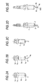
- a substantially cylindrical metal shell 1' which has not yet been subjected to a threading process is formed by a process such as a cold extrusion process and a cutting process.
- a tool engagement portion 1d having a hexagonal section shape is formed on one end side with respect to an axial middle portion 1b, and a thread forming portion 1a' which is substantially cylindrical, and in which the diameter is smaller than that of the center portion 1b, is formed on the other end side (see Fig. 2A).
- the ground electrode 4 having the tapered faces 4b formed at the tip end is resistance-welded to a tip end face 1e of the thread forming portion 1a' (see Fig. 2B). Then, a rolling process is applied to the thread forming portion 1a' of the metal shell 1' to form the thread portion 1a (Fig. 2C). Next, a surface treatment such as galvanizing is applied to the metal shell 1', and the insulator 2 holding the center electrode 3 to which the noble metal tip is welded to form the tip end portion 51 is attached to the metal shell 1' (Fig. 2D).
- the noble metal tip 52a is placed in a portion of the inner side face 4a which is positioned between the pair of tapered faces 4b, and in which the width is smaller than the original width of the ground electrode.
- the interface between the inner side face 4a and the noble metal tip 52a is irradiated with a laser beam in a substantially horizontal direction, thereby forming the discharge portion 52 in the ground electrode 4 (Fig. 2E).
- the ground electrode 4 in which the tapered faces are previously formed is resistance-welded to the ground electrode 4.
- the tapered faces may be formed after the resistance welding is conducted.
- the discharge portion 52 may be formed by provisionally welding the noble metal tip 52a on the side of the ground electrode to the inner side face 4a of the ground electrode 4 by resistance welding or the like, forming the tapered faces, and thereafter conducting laser welding.
- the tapered faces may be formed in the ground electrode 4 at any step so long as laser welding has not yet been conducted.
- Fig. 3 is a diagram showing positioning of the discharge portion 52 with respect to the inner side face 4a of the ground electrode 4, i.e., the minimum distance L between the tapered faces 4b and the tip end face 4c of the ground electrode 4, and the noble metal tip 52a.
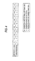
- Fig. 4 shows test results obtained in evaluating weldability in the case where the minimum distance L is set to have a value of 0 to 1.0 mm. The weldability was evaluated in the following manner.
- a spark plug was repeatedly subjected to 1,000 cycles in each of which the tip end of the spark plug on the side of the spark discharge gap was heated by a gas burner for two minutes to 1,000°C in the vicinity of the molten bond between the ground electrode 4 and the noble metal tip 52a, and then air cooled for one minute (corresponding to a travel distance of about 100,000 km in a durability test on an actual engine under usual traveling conditions). Then, the spark plug which had undergone the test was cut and polished in a plane passing through the center axis of the discharge portion 52, and the section was magnified and observed under a microscope. The length of an oxidized portion (oxidation length) at the interface between the noble metal tip 52a and the ground electrode 4 was measured in the observation field.
- the measured length of the oxidized portion was divided by the total length of the interface, and the division result was set as an oxidation rate.
- the oxidation rate was larger than 50% the weldability was judged not good ( ⁇ ), that in which the rate was 30 to 50% was judged to have good peel resistance ( ⁇ ), and that in which the rate was smaller than 30% was judged as being excellent (o ⁇ ).
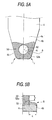
- Fig. 5 is a diagram showing a state after laser welding in the case where the discharge portion 52 is formed by placing the noble metal tip 52a on the inner side face 4a of the ground electrode 4 so as to attain the value ofL at which the best result is obtained.
- Fig. 5B is a partial sectional view taken along the line A-A' in Fig. 5A.
- a molten bond 53 is formed so as to extend from the inner side face 4a to the tapered faces 4b.
- the molten bond 53 has a curved shape which protrudes outward in a convex shape, and has a radius of curvature R, at a corner between the inner side face 4a and the tapered faces 4b.
- the radius of curvature R is in the range of 0.3 mm to 1.0 mm (in the examples, about 0.4 mm).
- a portion (unmelted portion) which is not melted by the laser welding has a height t of 0.45 mm.
- the minimum distance (the height t of the unmelted portion) between the tip end face of the noble metal tip 52a and the molten bond 53 is set to 0.3 mm or more. In the resulting structure, therefore, discharge at the molten bond hardly occurs.
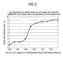
- the noble metal tip 52a is laser-welded so as to satisfy a relationship of t ⁇ 0.78 ⁇ S between the height (t) of the unmelted portion of the noble metal tip 52a and a horizontal sectional area S of the noble metal tip 52a.
- Fig. 6 shows that when tapered faces are formed after a noble metal tip satisfying t ⁇ 0.78 ⁇ S is laser-welded, the crack occurrence rate is high.
- the noble metal tip is welded to the ground electrode in which the tapered faces are previously formed. Even in the case of a noble metal tip satisfying t ⁇ 0.78 ⁇ S, therefore, it is possible to prevent cracks from occurring.
- the edges formed at a corner between the tapered faces 4b of the ground electrode and the tip end face 4c are melted by a laser beam to have a curved shape which protrudes outward in a convex shape, and which has a radius of curvature r.
- the electric field strength can be further suppressed from concentrating at such edges as compared with the case where the edges formed by the tapered faces 4b of the ground electrode and the tip end face 4c are angular as shown in Fig. 3. Therefore, this configuration prevents the molten bond 53 from becoming damaged.
- a middle portion of the molten bond 53 on the side of the metal shell (the rear end side) has an inward recessed shape.
- this portion has a structure in which the width (the minimum distance between the outer peripheral edge of the molten bond 53 and the outer peripheral face of the noble metal tip 52a) is smaller than the width of another portion.
- the reason therefor is as follows.
- the front face of the noble metal tip on the side of the metal shell is hardly irradiated with a laser beam, because of obstruction by the metal shell. Therefore, the laser irradiation is conducted in an oblique direction.
- the width of the molten bond is smaller than that of another portion. Even in such a shape, in order to obtain sufficient bonding strength between the noble metal tip 52a and the ground electrode 4, preferably, a minimum width of 0.25 mm or more is ensured in the recessed portion.
Landscapes
- Engineering & Computer Science (AREA)
- Manufacturing & Machinery (AREA)
- Spark Plugs (AREA)
Applications Claiming Priority (2)
| Application Number | Priority Date | Filing Date | Title |
|---|---|---|---|
| JP2003373436 | 2003-09-27 | ||
| JP2003373436 | 2003-09-27 |
Publications (3)
| Publication Number | Publication Date |
|---|---|
| EP1519460A2 true EP1519460A2 (de) | 2005-03-30 |
| EP1519460A3 EP1519460A3 (de) | 2013-05-29 |
| EP1519460B1 EP1519460B1 (de) | 2016-04-27 |
Family
ID=34191608
Family Applications (1)
| Application Number | Title | Priority Date | Filing Date |
|---|---|---|---|
| EP04255860.1A Expired - Lifetime EP1519460B1 (de) | 2003-09-27 | 2004-09-24 | Herstellungsverfahren einer Zündkerze und Zündkerze |
Country Status (1)
| Country | Link |
|---|---|
| EP (1) | EP1519460B1 (de) |
Citations (1)
| Publication number | Priority date | Publication date | Assignee | Title |
|---|---|---|---|---|
| US20020105254A1 (en) | 2001-02-08 | 2002-08-08 | Tsunenobu Hori | Structure of spark plug designed to provide higher durability and ignitability of fuel |
-
2004
- 2004-09-24 EP EP04255860.1A patent/EP1519460B1/de not_active Expired - Lifetime
Patent Citations (2)
| Publication number | Priority date | Publication date | Assignee | Title |
|---|---|---|---|---|
| US20020105254A1 (en) | 2001-02-08 | 2002-08-08 | Tsunenobu Hori | Structure of spark plug designed to provide higher durability and ignitability of fuel |
| JP2002237365A (ja) | 2001-02-08 | 2002-08-23 | Denso Corp | スパークプラグおよびその製造方法 |
Also Published As
| Publication number | Publication date |
|---|---|
| EP1519460A3 (de) | 2013-05-29 |
| EP1519460B1 (de) | 2016-04-27 |
Similar Documents
| Publication | Publication Date | Title |
|---|---|---|
| US7847472B2 (en) | Spark plug having noble metal tip | |
| JP4069826B2 (ja) | スパークプラグおよびその製造方法 | |
| JP4271379B2 (ja) | スパークプラグ | |
| KR101019813B1 (ko) | 스파크 플러그 제조방법 및 스파크 플러그 | |
| KR101395376B1 (ko) | 스파크 플러그 및 그 제조방법 | |
| JP4402731B2 (ja) | 内燃機関用スパークプラグ及びスパークプラグの製造方法 | |
| JP5044665B2 (ja) | スパークプラグ | |
| JPH0668955A (ja) | スパークプラグおよびその製造方法 | |
| JP2008077838A (ja) | 内燃機関用のスパークプラグ及びその製造方法 | |
| JP4230202B2 (ja) | スパークプラグおよびその製造方法 | |
| JP2002033176A (ja) | スパークプラグおよびその製造方法 | |
| EP1369969B1 (de) | Verfahren zur herstellung einer zündkerze | |
| JP2002222686A (ja) | スパークプラグおよびその製造方法 | |
| WO2010053099A1 (ja) | スパークプラグ及びスパークプラグの製造方法 | |
| JP4438794B2 (ja) | スパークプラグおよびその製造方法 | |
| EP1519460B1 (de) | Herstellungsverfahren einer Zündkerze und Zündkerze | |
| JP4075137B2 (ja) | スパークプラグ | |
| JP4414849B2 (ja) | スパークプラグの製造方法及びスパークプラグ | |
| US7323811B2 (en) | Noble metal tip for spark plug electrode and method of making same | |
| KR20040032933A (ko) | 내연기관용 점화플러그 및 그 제조방법 | |
| JP2000252039A (ja) | 内燃機関用スパークプラグ | |
| JP2890818B2 (ja) | 内燃機関用スパークプラグ | |
| JP2005108795A (ja) | スパークプラグの製造方法 | |
| JP2025121568A (ja) | 点火プラグ | |
| JP2009236070A (ja) | 内燃機関 |
Legal Events
| Date | Code | Title | Description |
|---|---|---|---|
| PUAI | Public reference made under article 153(3) epc to a published international application that has entered the european phase |
Free format text: ORIGINAL CODE: 0009012 |
|
| AK | Designated contracting states |
Kind code of ref document: A2 Designated state(s): AT BE BG CH CY CZ DE DK EE ES FI FR GB GR HU IE IT LI LU MC NL PL PT RO SE SI SK TR |
|
| AX | Request for extension of the european patent |
Extension state: AL HR LT LV MK |
|
| PUAL | Search report despatched |
Free format text: ORIGINAL CODE: 0009013 |
|
| AK | Designated contracting states |
Kind code of ref document: A3 Designated state(s): AT BE BG CH CY CZ DE DK EE ES FI FR GB GR HU IE IT LI LU MC NL PL PT RO SE SI SK TR |
|
| AX | Request for extension of the european patent |
Extension state: AL HR LT LV MK |
|
| RIC1 | Information provided on ipc code assigned before grant |
Ipc: H01T 13/39 20060101ALI20130423BHEP Ipc: H01T 21/02 20060101AFI20130423BHEP |
|
| 17P | Request for examination filed |
Effective date: 20130701 |
|
| RBV | Designated contracting states (corrected) |
Designated state(s): AT BE BG CH CY CZ DE DK EE ES FI FR GB GR HU IE IT LI LU MC NL PL PT RO SE SI SK TR |
|
| 17Q | First examination report despatched |
Effective date: 20130823 |
|
| AKX | Designation fees paid |
Designated state(s): DE FR |
|
| GRAP | Despatch of communication of intention to grant a patent |
Free format text: ORIGINAL CODE: EPIDOSNIGR1 |
|
| INTG | Intention to grant announced |
Effective date: 20151216 |
|
| RAP1 | Party data changed (applicant data changed or rights of an application transferred) |
Owner name: NGK SPARK PLUG CO., LTD. |
|
| RIN1 | Information on inventor provided before grant (corrected) |
Inventor name: SUZUKI, AKIRA C/O NGK SPARK PLUG CO LTD Inventor name: MATSUTANI, WATARU C/O NGK SPARK PLUG CO LTD |
|
| GRAS | Grant fee paid |
Free format text: ORIGINAL CODE: EPIDOSNIGR3 |
|
| GRAA | (expected) grant |
Free format text: ORIGINAL CODE: 0009210 |
|
| AK | Designated contracting states |
Kind code of ref document: B1 Designated state(s): DE FR |
|
| REG | Reference to a national code |
Ref country code: DE Ref legal event code: R096 Ref document number: 602004049152 Country of ref document: DE |
|
| REG | Reference to a national code |
Ref country code: FR Ref legal event code: PLFP Year of fee payment: 13 |
|
| REG | Reference to a national code |
Ref country code: DE Ref legal event code: R097 Ref document number: 602004049152 Country of ref document: DE |
|
| PLBE | No opposition filed within time limit |
Free format text: ORIGINAL CODE: 0009261 |
|
| STAA | Information on the status of an ep patent application or granted ep patent |
Free format text: STATUS: NO OPPOSITION FILED WITHIN TIME LIMIT |
|
| 26N | No opposition filed |
Effective date: 20170130 |
|
| REG | Reference to a national code |
Ref country code: FR Ref legal event code: PLFP Year of fee payment: 14 |
|
| REG | Reference to a national code |
Ref country code: FR Ref legal event code: PLFP Year of fee payment: 15 |
|
| P01 | Opt-out of the competence of the unified patent court (upc) registered |
Effective date: 20230512 |
|
| PGFP | Annual fee paid to national office [announced via postgrant information from national office to epo] |
Ref country code: FR Payment date: 20230808 Year of fee payment: 20 Ref country code: DE Payment date: 20230802 Year of fee payment: 20 |
|
| REG | Reference to a national code |
Ref country code: DE Ref legal event code: R081 Ref document number: 602004049152 Country of ref document: DE Owner name: NITERRA CO., LTD., NAGOYA-SHI, JP Free format text: FORMER OWNER: NGK SPARK PLUG CO., LTD., NAGOYA-SHI, AICHI-KEN, JP |
|
| REG | Reference to a national code |
Ref country code: DE Ref legal event code: R071 Ref document number: 602004049152 Country of ref document: DE |