EP1519141A2 - Rundum-Scanner - Google Patents
Rundum-Scanner Download PDFInfo
- Publication number
- EP1519141A2 EP1519141A2 EP04021150A EP04021150A EP1519141A2 EP 1519141 A2 EP1519141 A2 EP 1519141A2 EP 04021150 A EP04021150 A EP 04021150A EP 04021150 A EP04021150 A EP 04021150A EP 1519141 A2 EP1519141 A2 EP 1519141A2
- Authority
- EP
- European Patent Office
- Prior art keywords
- images
- camera
- projector
- rotation
- turntable
- Prior art date
- Legal status (The legal status is an assumption and is not a legal conclusion. Google has not performed a legal analysis and makes no representation as to the accuracy of the status listed.)
- Withdrawn
Links
Images


Classifications
-
- G—PHYSICS
- G01—MEASURING; TESTING
- G01B—MEASURING LENGTH, THICKNESS OR SIMILAR LINEAR DIMENSIONS; MEASURING ANGLES; MEASURING AREAS; MEASURING IRREGULARITIES OF SURFACES OR CONTOURS
- G01B11/00—Measuring arrangements characterised by the use of optical techniques
- G01B11/24—Measuring arrangements characterised by the use of optical techniques for measuring contours or curvatures
- G01B11/25—Measuring arrangements characterised by the use of optical techniques for measuring contours or curvatures by projecting a pattern, e.g. one or more lines, moiré fringes on the object
- G01B11/2509—Color coding
-
- G—PHYSICS
- G01—MEASURING; TESTING
- G01B—MEASURING LENGTH, THICKNESS OR SIMILAR LINEAR DIMENSIONS; MEASURING ANGLES; MEASURING AREAS; MEASURING IRREGULARITIES OF SURFACES OR CONTOURS
- G01B11/00—Measuring arrangements characterised by the use of optical techniques
- G01B11/24—Measuring arrangements characterised by the use of optical techniques for measuring contours or curvatures
- G01B11/25—Measuring arrangements characterised by the use of optical techniques for measuring contours or curvatures by projecting a pattern, e.g. one or more lines, moiré fringes on the object
- G01B11/2518—Projection by scanning of the object
- G01B11/2522—Projection by scanning of the object the position of the object changing and being recorded
Definitions
- the invention relates to a method for three-dimensional Capture of an object. Furthermore, the invention relates to a Apparatus for carrying out the method and a use the device and the method.
- Method for three-dimensional acquisition and digitization objects are used for various purposes, e.g. in the development, production and quality control of industrial products and components.
- Medical technology is used for example optical measuring methods for making the casings in the ear of portable hearing aids.
- a hearing aid wearer are doing this by an audiologist by means of a rubber-like plastic mass imprints of created external auditory meatus of the patient.
- stereo lithographic or similar methods To be able to apply must of the ear impressions three-dimensional Computer models are created. This process takes place so far with the hearing aid manufacturer.
- the precision scanners used are mostly as a laser scanner trained, in which a laser beam controlled is passed over the surface of the impression and the backscattered Light from a detector (e.g., a CCD camera) a direction other than the laser beam is observed. The surface coordinates of the impression are then triangulated calculated.
- VIVID 910 of the company Minolta becomes a line from the laser beam generated over the surface of the object to be detected, e.g. an ear impression, is moved. The picture of the line will again watched with a camera, taking out of deformation of the line image by triangulation on the surface coordinates be closed of the object to be detected can.
- Turntable Rotary Stage Controller
- a disadvantage of the known laser scanners are their high Acquisition costs, sometimes by the high-precision Mechanics of the turntable are caused.
- JP 2001108421 A is a 3D scanner for three-dimensional Capture an object known.
- a 3D scanner for three-dimensional Capture an object known When scanning rotated the object together with a reference object, on the markers are attached. So are different views photographed of the object and the reference object, wherein the Photos based on the marks on the reference object to a three-dimensional computer model are assembled.
- a disadvantage of the known method is that for some Applications insufficient compliance of the computer model with the real object.
- the object of the present invention is a method and an all-round scanner that specifies an object and especially an ear impression in a relatively simple manner and cost-effective manner with that for producing a hearing aid housing shell required accuracy three-dimensional can be detected.
- a projector For the three-dimensional detection of an object according to the invention are at least a projector, a camera as well Means for rotating the projector and the camera relative to required by the object.
- a two-dimensional Pattern e.g. a color pattern that is a redundant one Code contains, with known projection data on the Projected surface of the object.
- the projected color pattern is then connected to a camera, e.g. a CCD camera, from a deviating from the projection direction Direction added.
- a camera e.g. a CCD camera
- the object is preferably located on a turntable. Between two shots, the turntable rotates a predeterminable angle so that several, e.g. 60, object images per scope can be included.
- the object rotates 360 ° once around the Axis of rotation. Should only one section be used for an object can be digitized, so the object can also be a Angle can be rotated less than 360 °. It is still possible to increase the accuracy of the to be generated 3D model more than a complete revolution in detection an object is executed. An abort criterion for example, then five are completely executed for the scan Revolutions of the object.
- the 3D data of the frames on a common coordinate system be obtained.
- the scanner markings attached which when scanning their position opposite do not change the object.
- the markers are preferably on the Turntable or at the edge of the turntable.
- the marks are designed so that in each camera image a specific Number of these marks is visible and from these Marks the rotation angle of the object relative to the projector and the camera clearly and with the required Accuracy can be taken. A higher number of Markings increase the accuracy of the 3D reconstruction.
- the position of the markers moving with the object becomes advantageous with respect to a "world coordinate system" once exactly determined and communicated to the evaluation system. Then the relative position of the object to the projector and the camera or the angle of rotation of the turntable from the position and the Coding of the markers recorded in the object image in the Coordinate system can be determined. Successively recorded Single images or the resulting 3D data sets can then simply by a corresponding coordinate transformation merged into the overall view in the "world coordinate system" become.
- the invention has the advantage that in a simple and cost-effective Way a synchronization of the still images with the rotational movement of the object is achieved without For this a high-precision and accordingly expensive mechanics is required.
- a user of the wrap-around scanner are do not perform any calibration or adjustment except the attachment of the object to be measured on the Turntable. It was thus an easy to use, but nevertheless high-precision and cost-effective acquisition possibility created the 3D all-round surface of an object.
- the all-round scanner according to the invention therefore, e.g. excellent for Use by an audiologist suited by a patient created an impression and using the scanner digitized three-dimensionally, so that the obtained model data via data transmission (e-mail or similar) directly to Manufacturer of a housing shell can be transmitted. This will save time and costs in the production of a Hearing aid housing saved.
- the relative Camera coordinates of each shot can be determined.
- a few marks measured in the "world coordinate system” serve to link the image with this in relation to put.
- the individual object images then simply by a corresponding coordinate transformation be joined to the overall view.
- the markings are preferably designed to be contain a coding with the scope 1-n, e.g. in shape of a binary code.
- the markings contain some measuring positions (corners, lines, circles or similar).
- the markers recorded in the object images are displayed in each object image by a suitable image processing software automatically detected, decoded and measured.
- the markings are designed such that for each object image based on the markers contained therein a clear assignment of the spatial position the camera and the projector is possible.
- a development of the invention provides that the axis of rotation, around the object relative to the projector and the Camera rotates, relative to the projector and the camera panned can be.
- This is most easily achieved by using the turntable in at least one direction by a certain angle is tilted. This brings particular advantages in digitization of ear impressions, as these are relatively rugged could be.
- By pivoting the axis of rotation can be shading and thus gaps or inaccuracies in prevented the three-dimensional computer model.
- the markings are arranged and designed such that each object image next to the rotation angle and the angle to the pivoted the axis of rotation relative to a starting position is, can be detected.
- the starting point can be the Position of the axis of rotation in the preceding object image or serve a source position.
- At least two offset cameras available, so that the object simultaneously from different angles can be included.
- the cameras are relative the axis of rotation of the object to be detected in different Height attached, so that also undercuts the Object that is missing when using only one camera in the computer model would lead through the more Camera can be detected.
- On a pivoting movement of the Rotationstellers relative to the cameras can be omitted become.
- a second camera also used a second projector, so each one by one Camera-projector pair object images are generated.
- the self-calibration property of a wrap-around scanner according to the invention has the advantage that all the individual 3D object images simply put together to a 3D all-around image can be. There are no high demands on the Constancy of the rotational movement. A synchronization of Rotary movement with the image recordings is not required. It can therefore resort to a low-cost mechanics become. The accuracy of 3D capture can be easily understood Increasing the number of images per revolution can be increased.
- a device 1 is shown, the thereto serves, the three-dimensional object coordinates of a surface 2 of an object 3 to be detected.
- the device 1 comprises a projector 4 having a color pattern 5 on the surface 2 of the object 3 to be detected projected.
- a projector 4 having a color pattern 5 on the surface 2 of the object 3 to be detected projected.
- FIG Color samples 5 from a series of adjacent Color stripes composed.
- a two-dimensional color pattern instead of that shown in Figure 1 one-dimensional color pattern 5 to use.
- each Point P of the surface 2 of the object 3 is a projection plane g be assigned.
- the color pattern 5 are thus Projection data coded. That on the surface 2 of the object 3 projected color pattern 5 is detected by a camera 6 in converted an image 7 in which the point P on the surface 2 is transformed into the point P '.
- the projector 4 and the camera 6, in particular at known length of a base line 8 can by triangulation the three-dimensional spatial coordinates of the point P on the surface 2 can be calculated.
- the required data reduction and evaluation is carried out by an evaluation unit 9 performed.
- the color pattern is 5 designed so that the coding of the projection planes g as robust as possible against errors. Furthermore, through the Coding errors that are based on the coloring of the object, be eliminated.
- the colors of the color pattern 5 are described by the RGB model.
- the changes of the color values of the color pattern 5 take place by changing the color values in the individual color channels R, G and B.
- This color pattern 5 refers to the RGB model with a red color channel R, a green color channel G and a blue color channel B. Since color values in each color channel may only assume the minimum value and maximum value, there are a total of eight mixed colors, each of which has the be assigned to the following numbers: black 0 blue 1 green 2 cyan 3 red 4 magenta 5 yellow 6 White 7
- codewords of the color values was a length of four Color stripe selected, with adjacent codewords each overlap with three color stripes.
- the color changes were also assigned numerical values. Because in each of the three color channels the color value remain the same, fall off or increase, there are a total of 27 different Color changes of the mixed color, each with a number was assigned between 0 and 26. The length of the color changes associated codewords became equal to three color changes chosen, with adjacent codewords each with overlap two color changes.
- FIG. 2 shows the basic diagram of a wrap-around scanner according to FIG of the invention illustrated.
- the scanner includes one Turntable 10, which is rotatably mounted about its axis of symmetry is. On the turntable is one after the individual anatomical Conditions of a hearing aid wearer kind of Ohrabtik 11 attached.
- the ear impression 11 is intended for production an individually shaped shell of a wearable in the ear Hearing aid to be digitized.
- the capture of the ear impression done by means of coded illumination and triangulation.
- the all-round scanner includes a projector 12, the one color-coded pattern on the surface of the ear impression 11 projected. That projected onto the surface of the ear impression 11 Color pattern is by a CCD camera 13 in an image the ear impression 11 converted.
- the rotation of the Turntable 10 may be a variety of such illustrations different viewing angles are recorded. So that the individual images of the respective viewing angle can be assigned, are at the outer edge of the turntable 10 marks 14 attached. Next to the ear impression 11 will also include a number of these markers in each image 14 recorded.
- the images of the marks 14 are in the Object images by a computer 15 with a suitable Image processing software automatically detected, decoded and measure. Based on the angle information obtained from it turns the individual pictures into a three-dimensional one Computer model of the ear impression 11 calculated.
- the computer 15 is preferably not part of the actual all-round scanner, i.e. not with the turntable 10, the projector 12 and the Camera 13 arranged in a common housing. Much more can as computer 15 an external, powerful PC with suitable software.
- the all-round scanner has then via an interface to connect to the computer 15th
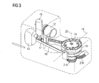
- Figure 3 shows the illustrated in Figure 2 in the schematic diagram All-round scanner in perspective view. Also from it are the turntable 10, a projector 12 and a CCD camera 13th in each position to each other visible. Furthermore is in Figure 3, the drive unit for the turntable 10 too remove. This includes a motor 16, which has a gear 17 and a toothed belt 18 drives the turntable 10. Farther is shown in Figure 3, a mechanism by which at the turntable 10 in addition to the rotational movement and a Pivoting movement is enabled. The pivot axis 19 extends in the embodiment by the intersection of the axis of rotation 20 with the surface of the turntable 10.
- the Pivoting movement takes place automatically in the exemplary embodiment by an electric drive, wherein in the shown Embodiment of the motor 16, both the rotational movement as also causes the pivoting movement.
- the Turntable 10 Through the rotation of the Turntable 10 is namely an associated gear 21A which is driven into a fixed in the housing of the scanner anchored tooth piece 21B engages and thereby to the pivoting movement the drive unit with the motor 16 and the timing belt 18 leads.
- the edge of the Turntable 10 attached markings 14 by means of which the exact angle of rotation of the turntable 10 and thus one mounted thereon object (see Figure 2) with respect to the projector 12 and the camera 13 from the generated images can be determined.
- the axis of rotation is at the beginning of Detection of an object in the appropriate starting position.
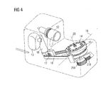
- This can e.g. be accomplished by that on the Enclosure of wrap-around scanner housing cover (not shown) is pivotally mounted. Before placing a Object on the turntable 10, this case cover must first be opened. When opening this housing cover Then the entire rotation unit with the motor 16 and the turntable 10 by a corresponding mechanism (not shown) transferred to its original position. At the start a scan is thus the turntable 10 in the in Figure 3 illustrated starting position until he finally after several revolutions the end position shown in Figure 4 occupies. In the final position of the engine 16 is self-acting stopped. Use the markers in the object images Each image of the angle of rotation and the angle to which the Turntable 10 is pivoted from its initial position, clearly remove. So can from the individual object images 3D model to be created with high accuracy.
- the turntable 10 for performing the pivotal movement also with a second engine (not shown) be connected.
- the pivoting movement can then also by the Calculator 15 can be controlled so that the number of revolutions of the turntable, in which this from a starting position in an end position pivots, is variable.
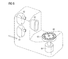
- FIG. 6 An alternative embodiment of a wrap-around scanner according to of the invention is shown in FIG. 6.
- the turntable 60 in this embodiment not swiveling.
- the Scanner two superimposed cameras 61 and 62, thus the object from different points of view to capture.
- the projector 63 is not punctiform Radiation source formed. Rather, he gives a coded Pattern starting from a vertical line from. This is the projection of the pattern on all areas of the object detected by the cameras.
- several projectors with punctiform Radiation source (not shown) can be used. Using multiple cameras will cause a panic motion of the turntable 60 lapsed and the drive unit can be compared to previous embodiments simplify.
- the turntable 60 directly (without the interposition of a toothed belt) driven.
- the all-round scanner according to FIG. 6 also has all the components from a common housing, so that too a compact and easy-to-use unit forms. Furthermore, inexpensive components available on the market can be used (CCD cameras, projectors) and especially one simple mechanics are resorted to.
Landscapes
- Engineering & Computer Science (AREA)
- Computer Vision & Pattern Recognition (AREA)
- Physics & Mathematics (AREA)
- General Physics & Mathematics (AREA)
- Length Measuring Devices By Optical Means (AREA)
Abstract
Description
- In jedem Farbkanal werden lediglich zwei Farbwerte verwendet. Insbesondere wird in jedem Farbkanal jeweils der Minimalwert und der Maximalwert verwendet, so dass im RGB-Modell insgesamt acht Farben zur Verfügung stehen.
- Innerhalb eines Codeworts weist jeder Farbkanal wenigstens eine Farbänderung auf. Diese Bedingung ermöglicht das Decodieren der einzelnen Codewörter.
- Nebeneinander liegende Farbelemente unterscheiden sich in wenigstens zwei Farbkanälen. Diese Bedingung dient insbesondere dazu, die Fehlertoleranz insbesondere gegen Tiefensprünge zu gewährleisten.
- Die einzelnen Codewörter des Farbmusters 5 weisen eine nicht-triviale Hamming-Distanz auf. Auch diese Bedingung dient dazu, die Fehlertoleranz beim Decodieren der Projektionsebenen g zu erhöhen.
- Auch die Farbänderungen werden zu Codewörtern mit einer nicht-trivialen Hamming-Distanz zusammengefasst.
| Schwarz | 0 |
| Blau | 1 |
| Grün | 2 |
| Cyan | 3 |
| Rot | 4 |
| Magenta | 5 |
| Gelb | 6 |
| Weiß | 7 |
1243070561217414270342127216534171614361605306352717072416305 250747147065035603634743506172524253607
Claims (29)
- Verfahren zur dreidimensionalen Erfassung eines Objekts (3; 11) mit folgenden Schritten:Bereitstellen des zu erfassenden Objekts (3; 11), eines Projektors (4; 12; 63), einer Kamera (6; 13; 61, 62) sowie Mitteln zur Rotation des Projektors (4; 12; 63) und der Kamera (6; 13; 61, 62) relativ zu dem Objekt (3; 11),Bereitstellen von Markierungen (14; 65) mit während der Rotation gleichbleibender Lage relativ zu dem Objekt (3; 11),Projektion eines Musters (5) auf das zu erfassende Objekt (3; 11) mittels des Projektors (4; 12; 63),Aufnahme eines Objektbildes (7) mittels der Kamera (6; 13; 61, 62), wobei in dem Objektbild (7) das Abbild wenigstens einer Markierung (14; 65) erfasst wird,Wiederholtes Verstellen des Projektors (4; 12; 63) und der Kamera (6; 13; 61, 62) relativ zu dem Objekt (3; 11) mit jeweiliger Projektion des Musters (5) und Aufnahme eines Objektbildes (7), so lange, bis ein Abbruchkriterium erreicht ist,Automatisches Zusammenfügen der Objektbilder oder aus diesen gewonnener Daten anhand der in den Objektbildern enthaltenen Abbilder der Markierungen (14, 65) und Erstellen eines dreidimensionalen Objektmodells.
- Verfahren nach Anspruch 1, wobei den Objektbildern (7) oder aus diesen gewonnener Daten anhand der in den Objektbildern enthaltenen Abbildern der Markierungen (14; 65) jeweils die räumliche Position des Objekts (3; 11) relativ zu dem Projektor (4; 12; 63) und der Kamera (6; 13; 61, 62) zugeordnet wird.
- Verfahren nach Anspruch 1 oder 2, wobei aus den Objektbildern 3D-Daten des Objekts (3; 11) in Bezug auf ein Koordinatensystem (X, Y, Z) ermittelt werden.
- Verfahren nach Anspruch 1 oder 2, wobei bei einer Umdrehung des Objekts (3; 11) um eine Rotationsachse (20) mehrere sich überlappende Objektbilder aufgenommen werden.
- Verfahren nach Anspruch 4, wobei Abbilder derselben Markierungen (14; 65) in zwei aufeinanderfolgenden Objektbildern enthalten sind.
- Verfahren nach einem der Ansprüche 1 bis 5, wobei die Markierungen (14; 65) kodiert sind.
- Verfahren nach Anspruch 6, wobei zur Kodierung ein Binärcode verwendet wird.
- Verfahren nach einem der Ansprüche 1 bis 7, wobei das Muster (5) ein strukturiertes Farbmuster ist.
- Verfahren nach Anspruch 8, wobei in dem Farbmuster (5) Projektionsdaten mit Hilfe eines redundanten Codes codiert werden.
- Verfahren nach einem der Ansprüche 1 bis 9, wobei eine Rotationsachse (20), um die das Objekt (3; 11) relativ zu dem Projektor (4; 12; 63) und der Kamera (6; 13; 61, 62) rotiert, während der Erfassung des Objekts (3; 11) relativ zu dem Projektor (4; 12; 63) und der Kamera (6; 13; 61, 62) automatisch geschwenkt wird.
- Verfahren nach Anspruch 10, wobei zwischen der Aufnahme aufeinanderfolgender Objektbilder sowohl eine Rotations- als auch eine Schwenkbewegung ausgeführt wird.
- Verfahren nach Anspruch 10 oder 11, wobei zum Schwenken der Rotationsachse (20) der Drehteller (10), auf dem das Objekt (11) gelagert ist, gegenüber dem Projektor (12) und der Kamera (13) automatisch geschwenkt wird.
- Verfahren nach einem der Ansprüche 10 bis 12, wobei den Objektbildern oder aus diesen gewonnener Daten anhand der in den Objektbildern enthaltenen Abbilder der Markierungen (14) jeweils ein Schwenkwinkel zugeordnet wird, um den die Rotationsachse (20) gegenüber einer Ausgangslage geschwenkt ist.
- Verfahren nach einem der Ansprüche 1 bis 9, wobei Objektbilder von zwei versetzt angeordneten Kameras (61, 62) aufgenommen werden.
- Rundum-Scanner zur dreidimensionalen Erfassung eines Objekts (3; 11) mit einem Projektor (4; 12, 63) zur Projektion eines Musters (5) auf das zu erfassende Objekt (3; 11), einer Kamera (6; 13; 61, 62) zum Erfassen von Objektbildern und Mitteln zur Rotation des Objekts (3; 11) relativ zu dem Projektor (4; 12; 63) und der Kamera (6; 13; 61, 62), wobei Markierungen (14; 65) vorhanden sind mit während der Rotation gleichbleibender Lage relativ zum Objekt (3; 11), wobei Abbilder der Markierungen in den Objektbildern vorhanden sind und wobei unter unterschiedlichen Drehwinkeln des Objekts (3; 11) relativ zu dem Projektor (4; 12; 63) und der Kamera (6; 13; 61, 62) erzeugte Objektbilder oder aus diesen gewonnene Daten anhand der in den Objektbildern vorhandenen Abbildungen der Markierungen (14; 65) zu einem dreidimensionalen Objektmodell zusammenfügbar sind.
- Rundum-Scanner nach Anspruch 15, wobei aus den Abbildern der Markierungen (14; 65) die räumliche Position des Objekts (3; 11) relativ zu dem Projektor (4; 12; 63) und/oder der Kamera (6; 13; 61, 62) ermittelbar ist.
- Rundum-Scanner nach Anspruch 16, wobei das Objekt (11) während eines Scans auf einem Drehteller (10; 60) gelagert ist.
- Rundum-Scanner nach Anspruch 17, wobei die Markierungen (14; 65) auf dem Drehteller (10; 60) angeordnet sind.
- Rundum-Scanner nach einem der Ansprüche 15 bis 18, wobei in jedem Objektbild das Abbild mehrerer Markierungen (14; 65) vorhanden ist.
- Rundum-Scanner nach einem der Ansprüche 17 bis 19, wobei der Projektor (12; 63), die Kamera (13; 61, 62), der Drehteller (10; 60) und die Antriebseinheit für den Drehteller (10; 60) als kompakte Baueinheit mit einem gemeinsamen Gehäuse (30) ausgebildet ist.
- Rundum-Scanner nach einem der Ansprüche 17 bis 20, wobei Mittel zum Schwenken der Rotationsachse (20) des Objekts (11) relativ zu dem Projektor (12) und der Kamera (13) vorhanden sind.
- Rundum-Scanner nach Anspruch 21, wobei aus den Abbildern der Markierungen (14) ein Schwenkwinkel ermittelbar ist, um den die Rotationsachse (20) gegenüber einer Ausgangslage geschwenkt ist.
- Rundum-Scanner nach Anspruch 21 oder 22, wobei die Rotationsachse (20) automatisch schwenkbar ist.
- Rundum-Scanner nach einem der Ansprüche 21 bis 23, wobei zum Schwenken der Rotationsachse (20) der Drehteller (10) schwenkbar gelagert ist.
- Rundum-Scanner nach Anspruch 24, wobei der Drehteller (10) zum automatischen Schwenken der Rotationsachse (20) mit einem Antrieb versehen ist.
- Rundum-Scanner nach Anspruch 25, wobei ein Antriebsmechanismus zur Rotation und zum Schwenken des Drehtellers (10) mit einem einzigen Motor (16) vorhanden ist.
- Rundum-Scanner nach einem der Ansprüche 15 bis 20, wobei eine erste und eine zweite Kamera (61, 62) vorhanden ist zum erfassen von Objektbildern aus unterschiedlichen Richtungen.
- Rundum-Scanner nach Anspruch 27, wobei ein erster und ein zweiter Projektor vorhanden ist zur Projektion von zweidimensionalen Mustern aus unterschiedlichen Richtungen auf das zu erfassende Objekt.
- Verwendung des Verfahrens nach einem der Ansprüche 1 bis 14 oder des Rundum-Scanners nach einem der Ansprüche 15 bis 28 zum dreidimensionalen Erfassen von Ohrabdrücken.
Applications Claiming Priority (2)
| Application Number | Priority Date | Filing Date | Title |
|---|---|---|---|
| DE2003144922 DE10344922B4 (de) | 2003-09-25 | 2003-09-25 | Rundum-Scanner |
| DE10344922 | 2003-09-25 |
Publications (2)
| Publication Number | Publication Date |
|---|---|
| EP1519141A2 true EP1519141A2 (de) | 2005-03-30 |
| EP1519141A3 EP1519141A3 (de) | 2009-03-04 |
Family
ID=34177985
Family Applications (1)
| Application Number | Title | Priority Date | Filing Date |
|---|---|---|---|
| EP04021150A Withdrawn EP1519141A3 (de) | 2003-09-25 | 2004-09-06 | Rundum-Scanner |
Country Status (5)
| Country | Link |
|---|---|
| EP (1) | EP1519141A3 (de) |
| JP (1) | JP2005099022A (de) |
| CN (1) | CN100381779C (de) |
| AU (1) | AU2004212587A1 (de) |
| DE (1) | DE10344922B4 (de) |
Cited By (21)
| Publication number | Priority date | Publication date | Assignee | Title |
|---|---|---|---|---|
| US7630088B2 (en) | 2005-04-15 | 2009-12-08 | Brother Kogyo Kabushiki Kaisha | Apparatus for measurement of 3-D shape of subject using transformable holder with stable and repeatable positioning of the same subject |
| WO2013110844A1 (es) * | 2012-01-26 | 2013-08-01 | Navarro Avino Enrique | Aparato y método para obtener esculturas y réplicas de personas a escala y color |
| WO2014149702A1 (en) * | 2013-03-15 | 2014-09-25 | Faro Technologies, Inc. | Three-dimensional coordinate scanner and method of operation |
| WO2015026847A1 (en) * | 2013-08-19 | 2015-02-26 | Aio Robotics, Inc. | Four-in-one three-dimensional copy machine |
| US9007601B2 (en) | 2010-04-21 | 2015-04-14 | Faro Technologies, Inc. | Automatic measurement of dimensional data with a laser tracker |
| US9041914B2 (en) | 2013-03-15 | 2015-05-26 | Faro Technologies, Inc. | Three-dimensional coordinate scanner and method of operation |
| US9086272B2 (en) | 2010-10-27 | 2015-07-21 | Nikon Corporation | Profile measuring apparatus, method for manufacturing structure, and structure manufacturing system |
| EP2460621A4 (de) * | 2009-07-31 | 2015-07-22 | Sumitomo Wiring Systems | Aufspannvorrichtung zur abmessung der grösse eines werkstücks |
| US9157987B2 (en) | 2011-04-15 | 2015-10-13 | Faro Technologies, Inc. | Absolute distance meter based on an undersampling method |
| US9164173B2 (en) | 2011-04-15 | 2015-10-20 | Faro Technologies, Inc. | Laser tracker that uses a fiber-optic coupler and an achromatic launch to align and collimate two wavelengths of light |
| US9377885B2 (en) | 2010-04-21 | 2016-06-28 | Faro Technologies, Inc. | Method and apparatus for locking onto a retroreflector with a laser tracker |
| US9395174B2 (en) | 2014-06-27 | 2016-07-19 | Faro Technologies, Inc. | Determining retroreflector orientation by optimizing spatial fit |
| US9400170B2 (en) | 2010-04-21 | 2016-07-26 | Faro Technologies, Inc. | Automatic measurement of dimensional data within an acceptance region by a laser tracker |
| US9453913B2 (en) | 2008-11-17 | 2016-09-27 | Faro Technologies, Inc. | Target apparatus for three-dimensional measurement system |
| WO2016150527A1 (de) * | 2015-03-23 | 2016-09-29 | Siemens Aktiengesellschaft | Verfahren und vorrichtung zur rekonstruktion von oberflächen mittels projektion von kodierten linienmustersequenzen |
| US9482529B2 (en) | 2011-04-15 | 2016-11-01 | Faro Technologies, Inc. | Three-dimensional coordinate scanner and method of operation |
| US9482755B2 (en) | 2008-11-17 | 2016-11-01 | Faro Technologies, Inc. | Measurement system having air temperature compensation between a target and a laser tracker |
| US9686532B2 (en) | 2011-04-15 | 2017-06-20 | Faro Technologies, Inc. | System and method of acquiring three-dimensional coordinates using multiple coordinate measurement devices |
| US9772394B2 (en) | 2010-04-21 | 2017-09-26 | Faro Technologies, Inc. | Method and apparatus for following an operator and locking onto a retroreflector with a laser tracker |
| US11049274B2 (en) | 2016-11-22 | 2021-06-29 | Lego A/S | System for acquiring a 3D digital representation of a physical object |
| US11650045B2 (en) | 2016-06-24 | 2023-05-16 | 3Shape A/S | 3D scanner using a structured beam of probe light |
Families Citing this family (53)
| Publication number | Priority date | Publication date | Assignee | Title |
|---|---|---|---|---|
| EP1996897B2 (de) * | 2006-03-23 | 2014-10-22 | Bernward Mähner | Verfahren zur räumlichen vermessung sich schnell bewegender objekte |
| DE102007017675A1 (de) * | 2007-04-14 | 2008-10-16 | Volkswagen Ag | Mobile Messeinrichtung |
| US8218903B2 (en) * | 2007-04-24 | 2012-07-10 | Sony Computer Entertainment Inc. | 3D object scanning using video camera and TV monitor |
| US8908995B2 (en) | 2009-01-12 | 2014-12-09 | Intermec Ip Corp. | Semi-automatic dimensioning with imager on a portable device |
| DE102009034993A1 (de) * | 2009-07-28 | 2011-02-10 | Siemens Medical Instruments Pte. Ltd. | Vorrichtung und Verfahren zum Erfassen der Gestalt eines Ohrabschnitts |
| EP2312268A1 (de) * | 2009-10-16 | 2011-04-20 | Straumann Holding AG | Abtastgerät zum Abtasten von dentalen Objekten und Verfahren zum Abtasten von dentalen Objekten |
| DE102010047444B4 (de) * | 2010-10-04 | 2014-04-03 | Audi Ag | Verfahren zur Visualisierung von Maßabweichungen zwischen einer Ist- und Soll-Geometrie eines Bauteils |
| DE102010050227A1 (de) * | 2010-11-04 | 2012-05-10 | Siemens Aktiengesellschaft | Endoskop mit 3D-Funktionalität |
| US9779546B2 (en) | 2012-05-04 | 2017-10-03 | Intermec Ip Corp. | Volume dimensioning systems and methods |
| US10007858B2 (en) | 2012-05-15 | 2018-06-26 | Honeywell International Inc. | Terminals and methods for dimensioning objects |
| US10321127B2 (en) | 2012-08-20 | 2019-06-11 | Intermec Ip Corp. | Volume dimensioning system calibration systems and methods |
| US9939259B2 (en) | 2012-10-04 | 2018-04-10 | Hand Held Products, Inc. | Measuring object dimensions using mobile computer |
| US20140104413A1 (en) | 2012-10-16 | 2014-04-17 | Hand Held Products, Inc. | Integrated dimensioning and weighing system |
| US9080856B2 (en) | 2013-03-13 | 2015-07-14 | Intermec Ip Corp. | Systems and methods for enhancing dimensioning, for example volume dimensioning |
| US10228452B2 (en) | 2013-06-07 | 2019-03-12 | Hand Held Products, Inc. | Method of error correction for 3D imaging device |
| US9464885B2 (en) | 2013-08-30 | 2016-10-11 | Hand Held Products, Inc. | System and method for package dimensioning |
| KR101484560B1 (ko) | 2013-12-31 | 2015-01-20 | 주식회사 메디트 | 3차원 형상 측정장치 |
| US9823059B2 (en) | 2014-08-06 | 2017-11-21 | Hand Held Products, Inc. | Dimensioning system with guided alignment |
| US10775165B2 (en) | 2014-10-10 | 2020-09-15 | Hand Held Products, Inc. | Methods for improving the accuracy of dimensioning-system measurements |
| US10810715B2 (en) | 2014-10-10 | 2020-10-20 | Hand Held Products, Inc | System and method for picking validation |
| US9779276B2 (en) | 2014-10-10 | 2017-10-03 | Hand Held Products, Inc. | Depth sensor based auto-focus system for an indicia scanner |
| GB2531928B (en) * | 2014-10-10 | 2018-12-12 | Hand Held Prod Inc | Image-stitching for dimensioning |
| US9897434B2 (en) | 2014-10-21 | 2018-02-20 | Hand Held Products, Inc. | Handheld dimensioning system with measurement-conformance feedback |
| US10060729B2 (en) | 2014-10-21 | 2018-08-28 | Hand Held Products, Inc. | Handheld dimensioner with data-quality indication |
| US9557166B2 (en) | 2014-10-21 | 2017-01-31 | Hand Held Products, Inc. | Dimensioning system with multipath interference mitigation |
| US9762793B2 (en) | 2014-10-21 | 2017-09-12 | Hand Held Products, Inc. | System and method for dimensioning |
| US9752864B2 (en) | 2014-10-21 | 2017-09-05 | Hand Held Products, Inc. | Handheld dimensioning system with feedback |
| US9786101B2 (en) | 2015-05-19 | 2017-10-10 | Hand Held Products, Inc. | Evaluating image values |
| US10066982B2 (en) | 2015-06-16 | 2018-09-04 | Hand Held Products, Inc. | Calibrating a volume dimensioner |
| US20160377414A1 (en) | 2015-06-23 | 2016-12-29 | Hand Held Products, Inc. | Optical pattern projector |
| US9857167B2 (en) | 2015-06-23 | 2018-01-02 | Hand Held Products, Inc. | Dual-projector three-dimensional scanner |
| US9835486B2 (en) | 2015-07-07 | 2017-12-05 | Hand Held Products, Inc. | Mobile dimensioner apparatus for use in commerce |
| EP3396313B1 (de) | 2015-07-15 | 2020-10-21 | Hand Held Products, Inc. | Verfahren und vorrichtung zur mobilen dimensionierung mit dynamischer nist-standardkonformer genauigkeit |
| US10094650B2 (en) | 2015-07-16 | 2018-10-09 | Hand Held Products, Inc. | Dimensioning and imaging items |
| US20170017301A1 (en) | 2015-07-16 | 2017-01-19 | Hand Held Products, Inc. | Adjusting dimensioning results using augmented reality |
| CN105180830B (zh) * | 2015-09-28 | 2017-09-01 | 浙江大学 | 一种适用于ToF相机的三维点云自动配准方法及系统 |
| JP2017083234A (ja) * | 2015-10-26 | 2017-05-18 | オムロン株式会社 | 三次元形状計測装置、三次元形状計測システム、プログラム、コンピュータ読み取り可能な記録媒体、および三次元形状計測方法 |
| US10249030B2 (en) | 2015-10-30 | 2019-04-02 | Hand Held Products, Inc. | Image transformation for indicia reading |
| US10225544B2 (en) | 2015-11-19 | 2019-03-05 | Hand Held Products, Inc. | High resolution dot pattern |
| US10025314B2 (en) | 2016-01-27 | 2018-07-17 | Hand Held Products, Inc. | Vehicle positioning and object avoidance |
| US10339352B2 (en) | 2016-06-03 | 2019-07-02 | Hand Held Products, Inc. | Wearable metrological apparatus |
| US9940721B2 (en) | 2016-06-10 | 2018-04-10 | Hand Held Products, Inc. | Scene change detection in a dimensioner |
| US10163216B2 (en) | 2016-06-15 | 2018-12-25 | Hand Held Products, Inc. | Automatic mode switching in a volume dimensioner |
| CN106679585A (zh) * | 2016-08-29 | 2017-05-17 | 广州魁科机电科技有限公司 | 一种用于三维扫描仪逆向测量的辅助装置 |
| JP6319395B2 (ja) * | 2016-10-14 | 2018-05-09 | オムロン株式会社 | 3次元測定装置および3次元測定方法 |
| US10909708B2 (en) | 2016-12-09 | 2021-02-02 | Hand Held Products, Inc. | Calibrating a dimensioner using ratios of measurable parameters of optic ally-perceptible geometric elements |
| US11047672B2 (en) | 2017-03-28 | 2021-06-29 | Hand Held Products, Inc. | System for optically dimensioning |
| US10733748B2 (en) | 2017-07-24 | 2020-08-04 | Hand Held Products, Inc. | Dual-pattern optical 3D dimensioning |
| US10584962B2 (en) | 2018-05-01 | 2020-03-10 | Hand Held Products, Inc | System and method for validating physical-item security |
| CN110830704B (zh) * | 2018-08-07 | 2021-10-22 | 纳宝株式会社 | 旋转图像生成方法及其装置 |
| US11639846B2 (en) | 2019-09-27 | 2023-05-02 | Honeywell International Inc. | Dual-pattern optical 3D dimensioning |
| CN114061488B (zh) * | 2021-11-15 | 2024-05-14 | 华中科技大学鄂州工业技术研究院 | 一种物体测量方法、系统以及计算机可读存储介质 |
| US12313398B2 (en) * | 2022-10-27 | 2025-05-27 | Tencent America LLC | Three-dimensional object scanning device and method |
Family Cites Families (13)
| Publication number | Priority date | Publication date | Assignee | Title |
|---|---|---|---|---|
| GB9002193D0 (en) * | 1990-01-31 | 1990-03-28 | Starsmore Neil | An imaging process for detecting the shape of three dimensional objects |
| DE4208455A1 (de) * | 1992-03-17 | 1993-09-23 | Peter Dr Ing Brueckner | Verfahren und anordnung zur beruehrungslosen dreidimensionalen messung |
| DE19502459A1 (de) * | 1995-01-28 | 1996-08-01 | Wolf Henning | Verfahren zur dreidimensionalen optischen Vermessung der Oberfläche von Objekten |
| DE19634254B4 (de) * | 1995-09-04 | 2009-06-10 | Volkswagen Ag | Optisch-numerisches Verfahren zur Ermittlung der gesamten Oberfläche eines dreidimensionalen Objektes |
| CN1205453A (zh) * | 1998-06-08 | 1999-01-20 | 北京大学 | 三维激光扫描仪 |
| DE19827788C2 (de) * | 1998-06-23 | 2003-08-28 | Dieter Dirksen | Vorrichtung und Verfahren zur dreidimensionalen Erfassung charakteristischer Messpunkte des Zahnbogens |
| DE19925462C1 (de) * | 1999-06-02 | 2001-02-15 | Daimler Chrysler Ag | Meß- und Prüfsystem sowie Meß- und Prüfverfahren für einen dreidimensionalen Körper in Zusammenhang mit dessen Fertigung |
| US6341016B1 (en) * | 1999-08-06 | 2002-01-22 | Michael Malione | Method and apparatus for measuring three-dimensional shape of object |
| JP2001108421A (ja) * | 1999-10-13 | 2001-04-20 | Sanyo Electric Co Ltd | 3次元モデリング装置、3次元モデリング方法および3次元モデリングプログラムを記録した媒体 |
| DE19963333A1 (de) * | 1999-12-27 | 2001-07-12 | Siemens Ag | Verfahren zur Ermittlung von dreidimensionalen Oberflächenkoordinaten |
| JP2003065736A (ja) * | 2001-08-24 | 2003-03-05 | Sanyo Electric Co Ltd | 3次元モデリング装置 |
| DE20115933U1 (de) * | 2001-09-27 | 2003-02-13 | Kaltenbach & Voigt | Vorrichtung zur Vermessung von dentalen Objekten |
| CN1403845A (zh) * | 2002-09-20 | 2003-03-19 | 力捷电脑(中国)有限公司 | 扫描头光学自动调整机构 |
-
2003
- 2003-09-25 DE DE2003144922 patent/DE10344922B4/de not_active Expired - Fee Related
-
2004
- 2004-09-06 EP EP04021150A patent/EP1519141A3/de not_active Withdrawn
- 2004-09-17 AU AU2004212587A patent/AU2004212587A1/en not_active Abandoned
- 2004-09-24 JP JP2004276526A patent/JP2005099022A/ja not_active Abandoned
- 2004-09-25 CN CNB2004100758805A patent/CN100381779C/zh not_active Expired - Fee Related
Cited By (37)
| Publication number | Priority date | Publication date | Assignee | Title |
|---|---|---|---|---|
| US7630088B2 (en) | 2005-04-15 | 2009-12-08 | Brother Kogyo Kabushiki Kaisha | Apparatus for measurement of 3-D shape of subject using transformable holder with stable and repeatable positioning of the same subject |
| US9453913B2 (en) | 2008-11-17 | 2016-09-27 | Faro Technologies, Inc. | Target apparatus for three-dimensional measurement system |
| US9482755B2 (en) | 2008-11-17 | 2016-11-01 | Faro Technologies, Inc. | Measurement system having air temperature compensation between a target and a laser tracker |
| EP2460621A4 (de) * | 2009-07-31 | 2015-07-22 | Sumitomo Wiring Systems | Aufspannvorrichtung zur abmessung der grösse eines werkstücks |
| US9772394B2 (en) | 2010-04-21 | 2017-09-26 | Faro Technologies, Inc. | Method and apparatus for following an operator and locking onto a retroreflector with a laser tracker |
| US9007601B2 (en) | 2010-04-21 | 2015-04-14 | Faro Technologies, Inc. | Automatic measurement of dimensional data with a laser tracker |
| US9146094B2 (en) | 2010-04-21 | 2015-09-29 | Faro Technologies, Inc. | Automatic measurement of dimensional data with a laser tracker |
| US9377885B2 (en) | 2010-04-21 | 2016-06-28 | Faro Technologies, Inc. | Method and apparatus for locking onto a retroreflector with a laser tracker |
| US10209059B2 (en) | 2010-04-21 | 2019-02-19 | Faro Technologies, Inc. | Method and apparatus for following an operator and locking onto a retroreflector with a laser tracker |
| US10480929B2 (en) | 2010-04-21 | 2019-11-19 | Faro Technologies, Inc. | Method and apparatus for following an operator and locking onto a retroreflector with a laser tracker |
| US9400170B2 (en) | 2010-04-21 | 2016-07-26 | Faro Technologies, Inc. | Automatic measurement of dimensional data within an acceptance region by a laser tracker |
| EP2633268B1 (de) * | 2010-10-27 | 2018-09-26 | Nikon Corporation | Profilmessungsvorrichtung und verfahren zur herstellung einer struktur |
| US9086272B2 (en) | 2010-10-27 | 2015-07-21 | Nikon Corporation | Profile measuring apparatus, method for manufacturing structure, and structure manufacturing system |
| US10119805B2 (en) | 2011-04-15 | 2018-11-06 | Faro Technologies, Inc. | Three-dimensional coordinate scanner and method of operation |
| US9157987B2 (en) | 2011-04-15 | 2015-10-13 | Faro Technologies, Inc. | Absolute distance meter based on an undersampling method |
| US10578423B2 (en) | 2011-04-15 | 2020-03-03 | Faro Technologies, Inc. | Diagnosing multipath interference and eliminating multipath interference in 3D scanners using projection patterns |
| US9448059B2 (en) | 2011-04-15 | 2016-09-20 | Faro Technologies, Inc. | Three-dimensional scanner with external tactical probe and illuminated guidance |
| US9207309B2 (en) | 2011-04-15 | 2015-12-08 | Faro Technologies, Inc. | Six degree-of-freedom laser tracker that cooperates with a remote line scanner |
| US10302413B2 (en) | 2011-04-15 | 2019-05-28 | Faro Technologies, Inc. | Six degree-of-freedom laser tracker that cooperates with a remote sensor |
| US9482746B2 (en) | 2011-04-15 | 2016-11-01 | Faro Technologies, Inc. | Six degree-of-freedom laser tracker that cooperates with a remote sensor |
| US9482529B2 (en) | 2011-04-15 | 2016-11-01 | Faro Technologies, Inc. | Three-dimensional coordinate scanner and method of operation |
| US9164173B2 (en) | 2011-04-15 | 2015-10-20 | Faro Technologies, Inc. | Laser tracker that uses a fiber-optic coupler and an achromatic launch to align and collimate two wavelengths of light |
| US9494412B2 (en) | 2011-04-15 | 2016-11-15 | Faro Technologies, Inc. | Diagnosing multipath interference and eliminating multipath interference in 3D scanners using automated repositioning |
| US9686532B2 (en) | 2011-04-15 | 2017-06-20 | Faro Technologies, Inc. | System and method of acquiring three-dimensional coordinates using multiple coordinate measurement devices |
| US10267619B2 (en) | 2011-04-15 | 2019-04-23 | Faro Technologies, Inc. | Three-dimensional coordinate scanner and method of operation |
| WO2013110844A1 (es) * | 2012-01-26 | 2013-08-01 | Navarro Avino Enrique | Aparato y método para obtener esculturas y réplicas de personas a escala y color |
| GB2527993B (en) * | 2013-03-15 | 2018-06-27 | Faro Tech Inc | Three-Dimensional Coordinate Scanner And Method Of Operation |
| US9041914B2 (en) | 2013-03-15 | 2015-05-26 | Faro Technologies, Inc. | Three-dimensional coordinate scanner and method of operation |
| WO2014149702A1 (en) * | 2013-03-15 | 2014-09-25 | Faro Technologies, Inc. | Three-dimensional coordinate scanner and method of operation |
| GB2527993A (en) * | 2013-03-15 | 2016-01-06 | Faro Tech Inc | Three-Dimensional Coordinate Scanner And Method Of Operation |
| WO2015026847A1 (en) * | 2013-08-19 | 2015-02-26 | Aio Robotics, Inc. | Four-in-one three-dimensional copy machine |
| US9395174B2 (en) | 2014-06-27 | 2016-07-19 | Faro Technologies, Inc. | Determining retroreflector orientation by optimizing spatial fit |
| WO2016150527A1 (de) * | 2015-03-23 | 2016-09-29 | Siemens Aktiengesellschaft | Verfahren und vorrichtung zur rekonstruktion von oberflächen mittels projektion von kodierten linienmustersequenzen |
| US11650045B2 (en) | 2016-06-24 | 2023-05-16 | 3Shape A/S | 3D scanner using a structured beam of probe light |
| US12072178B2 (en) | 2016-06-24 | 2024-08-27 | 3Shape A/S | 3D scanner using a structured beam of probe light |
| US12560425B2 (en) | 2016-06-24 | 2026-02-24 | 3Shape A/S | 3D scanner using a structured beam of probe light |
| US11049274B2 (en) | 2016-11-22 | 2021-06-29 | Lego A/S | System for acquiring a 3D digital representation of a physical object |
Also Published As
| Publication number | Publication date |
|---|---|
| EP1519141A3 (de) | 2009-03-04 |
| JP2005099022A (ja) | 2005-04-14 |
| DE10344922A1 (de) | 2005-05-25 |
| DE10344922B4 (de) | 2008-06-26 |
| CN100381779C (zh) | 2008-04-16 |
| CN1654922A (zh) | 2005-08-17 |
| AU2004212587A1 (en) | 2005-04-14 |
Similar Documents
| Publication | Publication Date | Title |
|---|---|---|
| DE10344922B4 (de) | Rundum-Scanner | |
| DE102012112322B4 (de) | Verfahren zum optischen Abtasten und Vermessen einer Umgebung | |
| DE102012112321B4 (de) | Vorrichtung zum optischen Abtasten und Vermessen einer Umgebung | |
| EP2079981B1 (de) | Vorrichtung und verfahren zum berührungslosen erfassen einer dreidimensionalen kontur | |
| DE19983341B4 (de) | Verfahren und Einrichtung zur Erfassung stereoskopischer Bilder unter Verwendung von Bildsensoren | |
| EP3467432B1 (de) | Verfahren zum betreiben einer vorrichtung zum erfassen der dreidimensionalen geometrie von objekten | |
| DE69628956T2 (de) | Abtastvorrichtung und -verfahren | |
| DE102008047816B4 (de) | Vorrichtung zur Ermittlung der 3D-Koordinaten eines Objekts, insbesondere eines Zahns | |
| DE69413204T2 (de) | Verfahren und vorrichtung zum sammeln von daten für die herstellung von künstlichen stützelementen oder austauschteilen für den menschlichen körper | |
| DE202012104890U1 (de) | Vorrichtung zum optischen Abtasten und Vermessen einer Umgebung | |
| DE102011114674C5 (de) | Verfahren und Vorrichtung zum Bestimmen der 3D-Koordinaten eines Objekts | |
| DE102016118562A1 (de) | Dreidimensionales bildgerät, das eine dichroitische kamera umfasst | |
| EP4020973A1 (de) | Hintergrund-wiedergabeeinrichtung, hintergrundwiedergabesystem, aufnahmesystem, kamerasystem, digitale kamera und verfahren zum steuern einer hintergrund-wiedergabeeinrichtung | |
| DE102017213779A1 (de) | Dreidimensionale Messvorrichtung | |
| DE102009032262A1 (de) | Verfahren zur Bestimmung der 3D-Koordinaten eines Objekts | |
| WO2000074374A1 (de) | Verfahren zur erfassung und darstellung eines oder mehrerer objekte, beispielsweise zähne | |
| DE102008002725B4 (de) | Verfahren und Vorrichtung zur 3D-Rekonstruktion | |
| DE102012023623B4 (de) | Verfahren zum Zusammensetzen von Teilaufnahmen einer Oberfläche eines Objektes zu einer Gesamtaufnahme des Objektes und System zum Erstellen einer Gesamtaufnahme eines Objektes | |
| EP0447531B1 (de) | Verfahren und vorrichtung zur dreidimensionalen optischen vermessung von insbesondere zähnen in der mundhöhle von patienten | |
| EP2026034A2 (de) | Vorrichtung zur Ermittlung der 3D-Koordinaten eines Objekts, insbesondere eines Zahns | |
| DE10049103A1 (de) | Vorrichtung zur Überlagerung von Röntgen-Videobildern | |
| DE102006042311B4 (de) | Dreidimensionale Vermessung von Objekten in einem erweiterten Winkelbereich | |
| EP2998694A9 (de) | Verfahren und vorrichtung zum bestimmen der 3d-koordinaten eines objekts | |
| DE102016012130A1 (de) | Optischer Scanner für Zahnabformungen, Digitalisierungsverfahren und System für Dentalmodelle | |
| DE10336736B4 (de) | Vorrichtung und Methode zur Aufnahme von Bildinformationen zum Erstellen eines dreidimensionalen Bildes |
Legal Events
| Date | Code | Title | Description |
|---|---|---|---|
| PUAI | Public reference made under article 153(3) epc to a published international application that has entered the european phase |
Free format text: ORIGINAL CODE: 0009012 |
|
| AK | Designated contracting states |
Kind code of ref document: A2 Designated state(s): AT BE BG CH CY CZ DE DK EE ES FI FR GB GR HU IE IT LI LU MC NL PL PT RO SE SI SK TR |
|
| AX | Request for extension of the european patent |
Extension state: AL HR LT LV MK |
|
| PUAL | Search report despatched |
Free format text: ORIGINAL CODE: 0009013 |
|
| AK | Designated contracting states |
Kind code of ref document: A3 Designated state(s): AT BE BG CH CY CZ DE DK EE ES FI FR GB GR HU IE IT LI LU MC NL PL PT RO SE SI SK TR |
|
| AX | Request for extension of the european patent |
Extension state: AL HR LT LV MK |
|
| AKX | Designation fees paid | ||
| STAA | Information on the status of an ep patent application or granted ep patent |
Free format text: STATUS: THE APPLICATION IS DEEMED TO BE WITHDRAWN |
|
| 18D | Application deemed to be withdrawn |
Effective date: 20090905 |
|
| REG | Reference to a national code |
Ref country code: DE Ref legal event code: 8566 |