EP1519110B1 - Arrangement de brûleur, en particulier pour un appareil de chauffe d'automobile - Google Patents
Arrangement de brûleur, en particulier pour un appareil de chauffe d'automobile Download PDFInfo
- Publication number
- EP1519110B1 EP1519110B1 EP20040012272 EP04012272A EP1519110B1 EP 1519110 B1 EP1519110 B1 EP 1519110B1 EP 20040012272 EP20040012272 EP 20040012272 EP 04012272 A EP04012272 A EP 04012272A EP 1519110 B1 EP1519110 B1 EP 1519110B1
- Authority
- EP
- European Patent Office
- Prior art keywords
- wall
- burning chamber
- bottom wall
- coating
- burner arrangement
- Prior art date
- Legal status (The legal status is an assumption and is not a legal conclusion. Google has not performed a legal analysis and makes no representation as to the accuracy of the status listed.)
- Expired - Lifetime
Links
Images

Classifications
-
- F—MECHANICAL ENGINEERING; LIGHTING; HEATING; WEAPONS; BLASTING
- F23—COMBUSTION APPARATUS; COMBUSTION PROCESSES
- F23D—BURNERS
- F23D3/00—Burners using capillary action
- F23D3/40—Burners using capillary action the capillary action taking place in one or more rigid porous bodies
-
- F—MECHANICAL ENGINEERING; LIGHTING; HEATING; WEAPONS; BLASTING
- F23—COMBUSTION APPARATUS; COMBUSTION PROCESSES
- F23D—BURNERS
- F23D11/00—Burners using a direct spraying action of liquid droplets or vaporised liquid into the combustion space
- F23D11/36—Details
- F23D11/44—Preheating devices; Vaporising devices
- F23D11/441—Vaporising devices incorporated with burners
- F23D11/448—Vaporising devices incorporated with burners heated by electrical means
-
- F—MECHANICAL ENGINEERING; LIGHTING; HEATING; WEAPONS; BLASTING
- F23—COMBUSTION APPARATUS; COMBUSTION PROCESSES
- F23M—CASINGS, LININGS, WALLS OR DOORS SPECIALLY ADAPTED FOR COMBUSTION CHAMBERS, e.g. FIREBRIDGES; DEVICES FOR DEFLECTING AIR, FLAMES OR COMBUSTION PRODUCTS IN COMBUSTION CHAMBERS; SAFETY ARRANGEMENTS SPECIALLY ADAPTED FOR COMBUSTION APPARATUS; DETAILS OF COMBUSTION CHAMBERS, NOT OTHERWISE PROVIDED FOR
- F23M5/00—Casings; Linings; Walls
-
- F—MECHANICAL ENGINEERING; LIGHTING; HEATING; WEAPONS; BLASTING
- F23—COMBUSTION APPARATUS; COMBUSTION PROCESSES
- F23M—CASINGS, LININGS, WALLS OR DOORS SPECIALLY ADAPTED FOR COMBUSTION CHAMBERS, e.g. FIREBRIDGES; DEVICES FOR DEFLECTING AIR, FLAMES OR COMBUSTION PRODUCTS IN COMBUSTION CHAMBERS; SAFETY ARRANGEMENTS SPECIALLY ADAPTED FOR COMBUSTION APPARATUS; DETAILS OF COMBUSTION CHAMBERS, NOT OTHERWISE PROVIDED FOR
- F23M2900/00—Special features of, or arrangements for combustion chambers
- F23M2900/05004—Special materials for walls or lining
Definitions
- the present invention relates to a burner arrangement, in particular for a heating appliance, comprising a wall area limiting a volume range with an elevated temperature in operation of the burner arrangement with respect to the surroundings, according to the preamble of claim 1.
- the fuel is introduced into a so-called evaporator fleece or other porous medium.
- the initially still liquid fuel is distributed by capillary action, is thus distributed over a comparatively large surface and evaporated there.
- so-called atomizer burners the fuel is introduced via atomizing nozzles under high pressure and mixed in this way with the air required for combustion.
- the temperature present in the same area plays a fundamental role. Too fast, sudden evaporation, which can occur at very high local temperatures, contributes to the formation of deposits. Too low temperatures can result in insufficient evaporation.
- From the EP 0 166 329 A is a burner assembly according to the preamble of claim 1.
- this known burner arrangement of the fuel to be burned is introduced into a gasification chamber formed in a housing.
- the housing enclosing the gasification chamber which can be made in one piece with a flame tube and a burner plate and thus also limits that volume region in which the combustion will take place, can be coated with a coating of ceramic material in the region of a wall enclosing the gasification chamber Wall to protect against the high temperatures occurring during combustion.
- the WO 95 31348 A discloses a combustion chamber burner for a vehicle heater.
- the combustion air is supplied via a centrally arranged in the combustion chamber nozzle.
- the fuel is introduced into a porous evaporator medium provided on a circumferential wall of a combustion chamber housing.
- the DE 101 36 292 A1 discloses an evaporative burner for a vehicle heater in which a liquid evaporative medium receiving porous liquid evaporator medium is disposed in the bottom portion of a combustion chamber to achieve thermal insulation between the combustion chamber and a metal plate carrying this, are provided on this plate isolation ribs, which only a punctual contact guarantee
- a burner arrangement in particular for a vehicle heater, comprising a wall area bounding a volume area with an elevated temperature in operation of the burner arrangement, which wall area is at least partially provided with a thermally insulating wall Coating is coated.
- a combustion chamber housing is provided which, together with a heat exchanger arrangement, delimits an exhaust gas backflow space, the combustion chamber housing and / or the heat exchanger arrangement being coated with a thermally insulating coating at least in their adjoining areas.
- the burner arrangement By at least partially coating the burner arrangement with a thermally insulating coating, it is ensured that the volume area surrounded or delimited in this way is thermally more decoupled from adjacent areas, so that the thermal interaction between this volume area and other areas becomes clear can be reduced.
- the coating have a thermal conductivity of less than 40 W / mK, preferably less than 20 W / mK, most preferably less than 5 W / mK.
- a material for such a coating ceramic material has proven especially. This is on the one hand in the production in a wide range, in particular also with regard to its thermal conductivity, adjustable, so that, if necessary, locally different areas of the thermal insulation can be adapted to the respective requirements occurring there.
- a ceramic coating has the advantage that they are very stable in the occurring in such burner assemblies temperatures of up to more than 1000 ° C and are not subject to excessive aging.
- the group of so-called oxide-ceramic materials, in particular ZrO 2 / Ca has proved to be particularly advantageous.
- the coating is provided on the side of the wall region facing the volume region.
- a combustion chamber housing may be provided with a bottom wall and a peripheral wall, which surround a combustion chamber, wherein the wall region comprises the bottom wall and / or the peripheral wall.
- a combustion chamber housing may be provided with a bottom wall and a circumferential wall, which surround a combustion chamber, wherein on the bottom wall or the peripheral wall designed for receiving an ignition organ Zündorganinghunt is provided and the wall region comprises a surrounding the Zündorganinghunt wall.
- a combustor shell having a bottom wall and a peripheral wall enclosing a combustor, wherein a fuel supply line arrangement is provided for supplying fuel into the combustor, which fuel supply line arrangement is in the region of the bottom wall and / or peripheral wall to the combustor is open, and wherein the wall region comprises a wall of the fuel supply line arrangement.
- a combustion chamber housing may be provided with a bottom wall and a peripheral wall, which surround a combustion chamber, wherein on the peripheral wall a flame cover is worn and wherein the wall region comprises the peripheral wall and / or a region of the flame cover standing in supporting contact with the peripheral wall.
- a combustion chamber housing with a bottom wall and a circumferential wall is provided which surround a combustion chamber, wherein the combustion chamber housing comprises a ring-like support element on which at least part of the bottom wall is carried as a separate assembly , and wherein the carrier element and / or the formed as a separate assembly part of the bottom wall, at least in their contacting areas at least partially coated with a thermally insulating coating.
- a combustion chamber housing is provided with a bottom wall and a peripheral wall which surround a combustion chamber, wherein the combustion chamber housing comprises a ring-like support member on which at least a portion of the peripheral wall is carried as a separate assembly, and wherein the Carrier element and / or formed as a separate assembly part of the peripheral wall are coated at least partially in their contacting areas at least partially with a thermally insulating coating.
- FIG. 1 and 2 is a section of a burner assembly according to the invention, constructed here according to the principle of an evaporator burner, designated by the reference numeral 10.
- This burner assembly 10 comprises a combustion chamber housing 12, which is formed with a substantially pot-like structure.
- the burner housing 12 comprises a bottom wall 14 and in the illustrated example so integrally ausgestaltet an outer peripheral wall 16. From the bottom wall 14 is in the central region thereof to the outer peripheral wall 16 is substantially centrally or coaxially arranged air inlet nozzle 18 from a plurality of air inlet openings 20 for insertion of combustion air into the combustion chamber 22 generally surrounded by the bottom wall 14 and the outer peripheral wall 16.
- a lateral projection 24 of the outer peripheral wall 16 is a generally designated 26 Zündorganinghunt formed.
- an ignition device so for example a Glühzündux, can be used to provide the high temperatures required to ignite the combustion can.
- this carries a flame tube 28, wherein on or in the flame tube 28 in turn, a so-called flame shutter 30 is carried with an opening 32 formed therein for the combustion products.
- a ring-like or cylindrically shaped porous evaporator medium 34 is provided on the combustion chamber 22 facing side of the outer peripheral wall 16.
- liquid fuel is introduced through the outer peripheral wall 16 in this porous evaporator medium 34 preferably at a plurality of circumferential positions.
- the liquid fuel is distributed in the porous evaporator medium, for example nonwoven material, foamed ceramic, braid, knitted fabric or the like, by capillary action and is thus distributed over practically the entire peripheral region of the outer peripheral wall 16.
- the fuel then evaporates to the combustion chamber 22 out and forms there with the introduced via the nozzle 18 combustion air, the ignitable air / fuel mixture.
- porous evaporation medium 40 is also provided on the lateral projection 24 or the wall 38 formed thereby, which likewise has a substantially cylindrical shape and can thus surround the glow-igniting element inserted into the chamber 26 at a small distance. Fuel is also introduced into this evaporator medium 40, in particular during the start phase, so that fuel is evaporated in the volume region surrounding the glow igniter, supported by the temperatures provided by the glow igniter, so that in this local region an ignitable mixture enriched very strongly with fuel vapor is produced.
- the outer peripheral wall 16 is coated with such a thermally insulating coating B 1 on its inner side, that is to say on the side on which the porous evaporator medium 34 is also positioned.
- thermally insulating coatings B i are generally identified by the fact that a thicker solid and thus darker line is present.
- Wall 14 is coated with such a coating B 2 , so that preferably the entire combustion chamber 22 lying towards the surface area of the outer peripheral wall 16 and the bottom wall 14 with the coatings B 1 and B 2 is coated.
- the Zündorganingsch 26 enclosing wall may be coated on its the Zündorganinghunt 26 side facing with a coating B 3 , so that thermal losses, especially in the start phase of the burner assembly 10 can be significantly reduced here.
- a support wall 42 through which the combustion chamber housing 12 is carried and which at the same time, as will be shown below, may limit an exhaust gas backflow space, such a coating B 4 may be provided.
- these components or at least one of them may be thermally insulated.
- thermally insulating coating B i is that this insulating effect can be obtained, although the components which then have this insulating effect can be produced in a conventional manner from metal material, for example in investment casting technology. This is a great advantage, in particular with regard to the shaping and also the production costs. There is no need to use components that are generally constructed of the thermally insulating material, such as ceramic material.
- Ceramic materials are very suitable for the construction of such thermally insulating coatings.
- Ceramic materials have the advantage that, depending on the composition, they are stable up to temperatures of more than 1700 ° C., ie they are not damaged by such temperatures.
- ceramic coatings can be applied with high precision, in particular also with respect to the thickness thereof.
- oxide-ceramic materials in which, for example, zirconium oxide (ZrO 2 ) forms the basis.
- ZrO 2 zirconium oxide
- the addition of other materials, such as calcium oxide (CaO) or calcium (Ca) it is possible to stabilize such oxide ceramic materials so that they remain stable to their occurring at very high temperatures structural transformations even with subsequent cooling to room temperature.
- Aluminum oxide is also an oxide-ceramic material which is particularly suitable for the present invention.
- non-oxide ceramic materials such as carbides, nitrides, borides or silicides can be used for the purposes of the present invention.
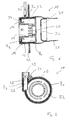
- Fig. 3 an embodiment of a burner assembly 10 according to the invention can be seen.
- the combustion chamber housing 12 has a ring-like carrier element 44.
- This carries with a longitudinal section a substantially the combustion chamber 22 radially outwardly delimiting and the predominantlyorswandung 16habstellendes cylindrical member 46.
- This is inserted into the annular support member until it comes to a radially inwardly projecting annular projection 48 for conditioning.
- the bottom wall 14 is supported.
- substantially cup-shaped flame arrester 30 is supported on the end region of the cylindrical component 46 facing away from the ring-like carrier element 44, which in turn carries the wall 42 already mentioned above on its area overlapping with the component 46, just like the only partially shown flame tube 28th
- Fig. 3 continue the inner and generally pot-shaped housing part 60 of a heat exchanger assembly 62.
- a coating is provided at several positions in order to reduce the outflow of heat. It can thus be seen that a coating B 5 is also provided here on the wall 42 in the area in which it is flown by the exhaust gases flowing back. Also, where the cylindrical portion 68 of the flame shutter 30 is in contact with the component 46, a corresponding coating is provided on this cylindrical portion 68 and / or on the component 46 or may be provided there, so that the heat input into the Flame diaphragm 30 can be reduced in this area.
- the ring-like carrier element 44 is coated in the region in which it is in supporting or holding contact with the component 46, with a coating B 6 , wherein, of course, this coating can be provided alternatively or additionally to the component 46. Also in that section in which the carrier element 44 cooperates with the bottom wall 14 and also with the other components 54, 56, 52, 50 following the bottom wall 14, a coating B 7 is provided on the inner peripheral side of the carrier element 44. Furthermore, a thermally insulating coating B 8 is provided on the side facing the combustion chamber 22 side of the bottom wall 14, as well as on the inner surface of the Brennstoffzu slaughtertechnisch 36 in that area in which it opens into the combustion chamber housing 12, a coating B g is provided.
Landscapes
- Engineering & Computer Science (AREA)
- Chemical & Material Sciences (AREA)
- Combustion & Propulsion (AREA)
- Mechanical Engineering (AREA)
- General Engineering & Computer Science (AREA)
- Spray-Type Burners (AREA)
- Combustion Of Fluid Fuel (AREA)
Claims (11)
- Un arrangement de brûleur, en particulier pour un dispositif de chauffage d'un véhicule, comprenant une section de paroi limitant une section de volume avec, quand l'arrangement de brûleur (10) est en service, une température élevée par rapport à l'environnement, la section de paroi étant au moins en partie recouverte d'un revêtement thermoisolant (Bi), de plus comprenant un boîtier de chambre de combustion (12) et un arrangement d'échangeur de chaleur (62), caractérisé par le boîtier de chambre de combustion (12) limitant conjointement avec l'arrangement d'échangeur de chaleur (62) un espace de reflux de gaz d'échappement (64), le boîtier de chambre de combustion (12) ou/et l'arrangement d'échangeur de chaleur (62) étant, au moins dans leurs régions adjacentes, recouverts d'un revêtement thermoisolant (Bj).
- Un arrangement de brûleur selon la revendication 1,
caractérisé par le revêtement (Bi, Bj) présentant une conductibilité de la chaleur de moins de 40 W/mK, de préférence de moins de 20 W/mK et le plus préféré de moins de 5 W/mK. - Un arrangement de brûleur selon la revendication 1 ou 2,
caractérisé par le revêtement (Bi, Bj) étant un revêtement céramique. - Un arrangement de brûleur selon la revendication 3,
caractérisé par le revêtement (Bi, Bj) étant un revêtement céramique oxide, de préférence un revêtement ZrO2/Ca. - Un arrangement de brûleur selon la revendication 1 à 4,
caractérisé par le revêtement (Bi, Bj) étant prévu au côté tourné vers la section de volume. - Un arrangement de brûleur selon une des revendications 1 à 5,
caractérisé par le boîtier de chambre de combustion (12) comprenant un paroi de fond (14) et un paroi circonférentiel (16) enfermant une chambre de combustion (22), la section de paroi comprenant le paroi de fond (14) ou/et le paroi circonférentiel (16). - Un arrangement de brûleur selon une des revendications 1 à 6,
caractérisé par le boîtier de chambre de combustion (12) comprenant un paroi de fond (14) et un paroi circonférentiel (16) enfermant une chambre de combustion (22), une chambre de réception d'un élément d'allumage (26) pour recevoir l'élément d'allumage étant prévue au paroi de fond (14) ou au paroi circonférentiel (16), la section de paroi comprenant un paroi (36) enfermant la chambre de réception d'un élément d'allumage (26). - Un arrangement de brûleur selon une des revendications 1 à 7,
caractérisé par le boîtier de chambre de combustion (12) comprenant un paroi de fond (14) et un paroi circonférentiel (16) enfermant une chambre de combustion (22), un arrangement de conduit d'alimentation en combustible (36) pour alimenter la chambre de combustion (22) en combustible étant prévu, ledit arrangement de conduit d'alimentation en combustible (36) étant ouvert envers la chambre de combustion (22) dans la région du paroi de fond (14) ou/et du paroi circonférentiel (16), et la section de paroi comprenant un paroi de l'arrangement de conduit d'alimentation en combustible (36). - Un arrangement de brûleur selon une des revendications 1 à 8,
caractérisé par le boîtier de chambre de combustion (12) comprenant un paroi de fond (14) et un paroi circonférentiel (16) enfermant une chambre de combustion (22), un obturateur de flamme (30) étant supporté au paroi circonférentiel (16) et la section de paroi comprenant le paroi circonférentiel (16) ou/et une région (68) de l'obturateur de flamme (30) qui est en contact de support avec le paroi circonférentiel (16). - Un arrangement de brûleur selon une des revendications 1 à 9,
caractérisé par le boîtier de chambre de combustion (12) comprenant un paroi de fond (14) et un paroi circonférentiel (16) enfermant une chambre de combustion (22), le boîtier de chambre de combustion (12) comprenant un élément de support annulaire (44), auquel au moins une partie du paroi de fond (14) est supportée en tant que module séparé, et l'élément de support (44) ou/et la partie du paroi de fond (14) qui est formée en tant que module séparé étant recouverts au moins en partie par un revêtement thermoisolant (Bk), au moins dans leurs régions qui sont en contact mutuel. - Un arrangement de brûleur selon une des revendications 1 à 10,
caractérisé par le boîtier de chambre de combustion (12) comprenant un paroi de fond (14) et un paroi circonférentiel (16) enfermant une chambre de combustion (22), le boîtier de chambre de combustion (12) comprenant un élément de support annulaire (44), auquel au moins une partie (48) du paroi circonférentiel (16) est supportée en tant que module séparé, et l'élément de support (44) ou/et la partie (48) du paroi circonférentiel (16) qui est formée en tant que module séparé étant recouverts au moins en partie par un revêtement thermoisolant (BI), au moins dans leurs régions qui sont en contact mutuel.
Applications Claiming Priority (2)
| Application Number | Priority Date | Filing Date | Title |
|---|---|---|---|
| DE10343282 | 2003-09-18 | ||
| DE2003143282 DE10343282B3 (de) | 2003-09-18 | 2003-09-18 | Brenneranordnung, insbesondere für ein Fahrzeugheizgerät |
Publications (2)
| Publication Number | Publication Date |
|---|---|
| EP1519110A1 EP1519110A1 (fr) | 2005-03-30 |
| EP1519110B1 true EP1519110B1 (fr) | 2011-01-26 |
Family
ID=34177821
Family Applications (1)
| Application Number | Title | Priority Date | Filing Date |
|---|---|---|---|
| EP20040012272 Expired - Lifetime EP1519110B1 (fr) | 2003-09-18 | 2004-05-24 | Arrangement de brûleur, en particulier pour un appareil de chauffe d'automobile |
Country Status (2)
| Country | Link |
|---|---|
| EP (1) | EP1519110B1 (fr) |
| DE (2) | DE10343282B3 (fr) |
Families Citing this family (11)
| Publication number | Priority date | Publication date | Assignee | Title |
|---|---|---|---|---|
| DE102004049902B4 (de) * | 2004-10-13 | 2006-07-20 | Webasto Ag | Verdampfungsbrenner für flüssigen Brennstoff und Verfahren zu seinem Betrieb |
| DE102005004359A1 (de) * | 2005-01-31 | 2006-08-03 | J. Eberspächer GmbH & Co. KG | Brennkammergehäuse für einen Verdampferbrenner |
| DE102005032980B4 (de) * | 2005-07-14 | 2008-04-24 | J. Eberspächer GmbH & Co. KG | Brennkammerbaugruppe für einen Verdampferbrenner |
| DE102007061518A1 (de) * | 2007-12-20 | 2009-06-25 | J. Eberspächer GmbH & Co. KG | Brennkammerbaugruppe für einen Verdampferbrenner, insbesondere für ein Fahrzeugheizgerät |
| DE102010016158B4 (de) * | 2010-03-26 | 2012-08-16 | Webasto Ag | Brennkammeranordnung für einen Verdampferbrenner |
| DE102014103813A1 (de) | 2014-03-20 | 2015-09-24 | Webasto SE | Verdampferbrenneranordnung für ein mobiles, mit flüssigem Brennstoff betriebenes Heizgerät |
| DE102014103815B4 (de) * | 2014-03-20 | 2018-07-19 | Webasto SE | Verdampferbrenner |
| DE102014103812A1 (de) | 2014-03-20 | 2015-09-24 | Webasto SE | Verdampferbrenner für ein mobiles, mit flüssigem Brennstoff betriebenes Heizgerät |
| DE102014103817B4 (de) | 2014-03-20 | 2018-07-19 | Webasto SE | Verdampferbrenner für ein mobiles, mit flüssigem Brennstoff betriebenes Heizgerät |
| DE102016015762B4 (de) | 2016-09-15 | 2020-07-30 | Eberspächer Climate Control Systems GmbH & Co. KG | Brennkammerbaugruppe für ein brennstoffbetriebenes Fahrzeugheizgerät |
| DE102016117408B4 (de) * | 2016-09-15 | 2020-11-26 | Eberspächer Climate Control Systems GmbH | Brennkammerbaugruppe für ein brennstoffbetriebenes Fahrzeugheizgerät |
Family Cites Families (8)
| Publication number | Priority date | Publication date | Assignee | Title |
|---|---|---|---|---|
| DE3343617A1 (de) * | 1983-12-02 | 1985-06-13 | Fa. J. Eberspächer, 7300 Esslingen | Ultraschallzerstaeuber-brenner fuer kleinere heizgeraete |
| ATE37224T1 (de) | 1984-06-25 | 1988-09-15 | Vth Ag | Brenner, insbesondere brenner zur verbrennung von fluessigen brennstoffen in gasfoermigem zustand. |
| EP0758959A1 (fr) | 1994-05-13 | 1997-02-26 | J. Eberspächer GmbH & Co. | Chambre de combustion du bruleur d'un appareil de chauffage pour vehicule ou d'un filtre contre les particules de gaz d'echappement |
| DE19529994C2 (de) * | 1994-11-10 | 2003-06-26 | Eberspaecher J Gmbh & Co | Verdampferbrenner für ein Heizgerät |
| DE19934488A1 (de) * | 1999-07-22 | 2001-02-01 | Webasto Thermosysteme Gmbh | Brennstoffbetriebenes Heizgerät |
| DE10136292A1 (de) | 2001-07-25 | 2003-02-13 | Eberspaecher J Gmbh & Co | Verdampferbrenner |
| DE10144408B4 (de) * | 2001-09-10 | 2007-05-10 | Webasto Ag | Düse zum Zerstäuben von flüssigem Brennstoff |
| DE10200524C5 (de) * | 2002-01-09 | 2008-07-17 | J. Eberspächer GmbH & Co. KG | Brennkammerbaugruppe, insbesondere für ein Fahrzeugheizgerät |
-
2003
- 2003-09-18 DE DE2003143282 patent/DE10343282B3/de not_active Expired - Fee Related
-
2004
- 2004-05-24 EP EP20040012272 patent/EP1519110B1/fr not_active Expired - Lifetime
- 2004-05-24 DE DE200450012141 patent/DE502004012141D1/de not_active Expired - Lifetime
Also Published As
| Publication number | Publication date |
|---|---|
| DE10343282B3 (de) | 2005-04-21 |
| DE502004012141D1 (de) | 2011-03-10 |
| EP1519110A1 (fr) | 2005-03-30 |
Similar Documents
| Publication | Publication Date | Title |
|---|---|---|
| EP1519110B1 (fr) | Arrangement de brûleur, en particulier pour un appareil de chauffe d'automobile | |
| EP1860379A2 (fr) | Composant d'évaporateur, en particulier pour un appareil de chauffage de véhicule ou un dispositif de réformateur de carburant d'un système à cellules combustibles | |
| DE19717544A1 (de) | Verdampferbrenner für ein Heizgerät oder eine thermische Regeneration eines Abgas-Partikelfilters | |
| DE1609529C3 (de) | Heizanlage mit Heizkammer und Vorwärmung der Zuluft | |
| EP1696175B1 (fr) | Chemise de chambre de combustion de brûleur à vaporisation | |
| DE10130638A1 (de) | Verdampferbrenner | |
| DE102005032980B4 (de) | Brennkammerbaugruppe für einen Verdampferbrenner | |
| EP1484552B1 (fr) | Chambre de combustion pour un brûleur à vaporisation, en particulier pour le chauffage d'un véhicule | |
| DE4216523C2 (de) | Brenner für ein mit flüssigem Brennstoff betriebenes Heizgerät, insbesondere Fahrzeugzusatzheizgerät | |
| DE3343617A1 (de) | Ultraschallzerstaeuber-brenner fuer kleinere heizgeraete | |
| DE10200524C1 (de) | Brennkammerbaugruppe, insbesondere für ein Fahrzeugheizgerät | |
| DE10255361B3 (de) | Brennkammerbaugruppe für ein Heizgerät, insbesondere Fahrzeugheizgerät | |
| DE102011084868B4 (de) | Verdampferbrenner, insbesondere für ein Fahrzeugheizgerät | |
| EP1918639B1 (fr) | Composant de brûleur | |
| DE19926264B4 (de) | Heizgerät | |
| EP1342949A1 (fr) | Elément d'évaporateur d'un brûleur à vaporisation | |
| EP1788305B1 (fr) | Ensemble de chambre de combustion pour un brûleur à évaporation | |
| DE19521296A1 (de) | Verdampfungsbrenner | |
| DE102008019532B3 (de) | Ölvormischbrenner | |
| DE3509346A1 (de) | Waermetauscher fuer heizgeraete | |
| DE10207953B4 (de) | Heizgerät, insbesondere für ein Fahrzeug | |
| DE10323899B3 (de) | Brennkammeranordnung | |
| DE102007021760B4 (de) | Kleinleistungsbrenner, Brennereinrichtung mit einem Pilotbrenner und Thermogenerator | |
| AT211937B (de) | Heizölbrenner mit einer in der Form eines endlosen Kanales ausgebildeten geschlossenen Verdampfungskammer | |
| DE9419506U1 (de) | Wärmespeicherofen |
Legal Events
| Date | Code | Title | Description |
|---|---|---|---|
| PUAI | Public reference made under article 153(3) epc to a published international application that has entered the european phase |
Free format text: ORIGINAL CODE: 0009012 |
|
| AK | Designated contracting states |
Kind code of ref document: A1 Designated state(s): AT BE BG CH CY CZ DE DK EE ES FI FR GB GR HU IE IT LI LU MC NL PL PT RO SE SI SK TR |
|
| AX | Request for extension of the european patent |
Extension state: AL HR LT LV MK |
|
| 17P | Request for examination filed |
Effective date: 20050322 |
|
| AKX | Designation fees paid |
Designated state(s): CZ DE GB SE |
|
| 17Q | First examination report despatched |
Effective date: 20100216 |
|
| GRAP | Despatch of communication of intention to grant a patent |
Free format text: ORIGINAL CODE: EPIDOSNIGR1 |
|
| GRAS | Grant fee paid |
Free format text: ORIGINAL CODE: EPIDOSNIGR3 |
|
| GRAA | (expected) grant |
Free format text: ORIGINAL CODE: 0009210 |
|
| AK | Designated contracting states |
Kind code of ref document: B1 Designated state(s): CZ DE GB SE |
|
| REG | Reference to a national code |
Ref country code: GB Ref legal event code: FG4D Free format text: NOT ENGLISH |
|
| REF | Corresponds to: |
Ref document number: 502004012141 Country of ref document: DE Date of ref document: 20110310 Kind code of ref document: P |
|
| REG | Reference to a national code |
Ref country code: DE Ref legal event code: R096 Ref document number: 502004012141 Country of ref document: DE Effective date: 20110310 |
|
| REG | Reference to a national code |
Ref country code: SE Ref legal event code: TRGR |
|
| PG25 | Lapsed in a contracting state [announced via postgrant information from national office to epo] |
Ref country code: CZ Free format text: LAPSE BECAUSE OF FAILURE TO SUBMIT A TRANSLATION OF THE DESCRIPTION OR TO PAY THE FEE WITHIN THE PRESCRIBED TIME-LIMIT Effective date: 20110126 |
|
| PLBE | No opposition filed within time limit |
Free format text: ORIGINAL CODE: 0009261 |
|
| STAA | Information on the status of an ep patent application or granted ep patent |
Free format text: STATUS: NO OPPOSITION FILED WITHIN TIME LIMIT |
|
| 26N | No opposition filed |
Effective date: 20111027 |
|
| REG | Reference to a national code |
Ref country code: SE Ref legal event code: EUG |
|
| GBPC | Gb: european patent ceased through non-payment of renewal fee |
Effective date: 20110524 |
|
| REG | Reference to a national code |
Ref country code: DE Ref legal event code: R097 Ref document number: 502004012141 Country of ref document: DE Effective date: 20111027 |
|
| PG25 | Lapsed in a contracting state [announced via postgrant information from national office to epo] |
Ref country code: GB Free format text: LAPSE BECAUSE OF NON-PAYMENT OF DUE FEES Effective date: 20110524 |
|
| PG25 | Lapsed in a contracting state [announced via postgrant information from national office to epo] |
Ref country code: SE Free format text: LAPSE BECAUSE OF NON-PAYMENT OF DUE FEES Effective date: 20110525 |
|
| REG | Reference to a national code |
Ref country code: DE Ref legal event code: R082 Ref document number: 502004012141 Country of ref document: DE Representative=s name: WEICKMANN & WEICKMANN, DE |
|
| REG | Reference to a national code |
Ref country code: DE Ref legal event code: R082 Ref document number: 502004012141 Country of ref document: DE Representative=s name: WEICKMANN & WEICKMANN, DE Effective date: 20130607 Ref country code: DE Ref legal event code: R081 Ref document number: 502004012141 Country of ref document: DE Owner name: EBERSPAECHER CLIMATE CONTROL SYSTEMS GMBH & CO, DE Free format text: FORMER OWNER: J. EBERSPAECHER GMBH & CO. KG, 73730 ESSLINGEN, DE Effective date: 20130607 Ref country code: DE Ref legal event code: R082 Ref document number: 502004012141 Country of ref document: DE Representative=s name: RUTTENSPERGER LACHNIT TROSSIN GOMOLL PATENT- U, DE Effective date: 20130607 Ref country code: DE Ref legal event code: R082 Ref document number: 502004012141 Country of ref document: DE Representative=s name: RUTTENSPERGER LACHNIT TROSSIN GOMOLL, PATENT- , DE Effective date: 20130607 |
|
| REG | Reference to a national code |
Ref country code: DE Ref legal event code: R082 Ref document number: 502004012141 Country of ref document: DE Representative=s name: RUTTENSPERGER LACHNIT TROSSIN GOMOLL PATENT- U, DE Ref country code: DE Ref legal event code: R082 Ref document number: 502004012141 Country of ref document: DE Representative=s name: RUTTENSPERGER LACHNIT TROSSIN GOMOLL, PATENT- , DE |
|
| PGFP | Annual fee paid to national office [announced via postgrant information from national office to epo] |
Ref country code: DE Payment date: 20160531 Year of fee payment: 13 |
|
| REG | Reference to a national code |
Ref country code: DE Ref legal event code: R119 Ref document number: 502004012141 Country of ref document: DE |
|
| PG25 | Lapsed in a contracting state [announced via postgrant information from national office to epo] |
Ref country code: DE Free format text: LAPSE BECAUSE OF NON-PAYMENT OF DUE FEES Effective date: 20171201 |