EP1518967A1 - Flood barrier - Google Patents
Flood barrier Download PDFInfo
- Publication number
- EP1518967A1 EP1518967A1 EP04292098A EP04292098A EP1518967A1 EP 1518967 A1 EP1518967 A1 EP 1518967A1 EP 04292098 A EP04292098 A EP 04292098A EP 04292098 A EP04292098 A EP 04292098A EP 1518967 A1 EP1518967 A1 EP 1518967A1
- Authority
- EP
- European Patent Office
- Prior art keywords
- panels
- panel
- support
- sealing
- edges
- Prior art date
- Legal status (The legal status is an assumption and is not a legal conclusion. Google has not performed a legal analysis and makes no representation as to the accuracy of the status listed.)
- Withdrawn
Links
Images


Classifications
-
- E—FIXED CONSTRUCTIONS
- E02—HYDRAULIC ENGINEERING; FOUNDATIONS; SOIL SHIFTING
- E02B—HYDRAULIC ENGINEERING
- E02B3/00—Engineering works in connection with control or use of streams, rivers, coasts, or other marine sites; Sealings or joints for engineering works in general
- E02B3/04—Structures or apparatus for, or methods of, protecting banks, coasts, or harbours
- E02B3/10—Dams; Dykes; Sluice ways or other structures for dykes, dams, or the like
- E02B3/102—Permanently installed raisable dykes
Definitions
- the subject of the present invention is a device for construction of a flood-proof or flood-proof barrier on a support.
- the present invention relates to individual structures demountable and reassemblable parts used to temporarily watertight and usable barriers especially in case of flood risk sudden to protect facilities. More generally, this technical barriers are used to protect public or deprived of the effects of a sudden flood coming from the overflow of a stretch or stream.
- cofferdams made by stacking metal profiles that are often made of aluminum. They are slipped between columns with an H-shaped cross-section and come to rest on a flat surface. The assembly of these cofferdams often requires a machine lifting to set up the poles, and the establishment of profiles is relatively long.
- the present invention relates to a device for carrying out a barrier of the same type as that described in the PCT patent application referred to above, but which of course does not does not have the disadvantages.
- each panel is held on the support by the compression means of the panels which are, on the one hand, anchored in the support and which, on the other hand, cooperate with each panel. It results that, thanks to the presence of elastically deformable means, we obtain in a safe and simple way a very good seal between the support and the lower end of the panels. In addition, the panels being at least partially in compression, they exhibit a increased mechanical resistance to the water to be contained and their vertical retention is ensured effectively.
- the deformable means comprise a carpet disposed on said support.
- the means for compressing the panels cooperate with the top edge of the submitting panels thus all the panels to the compressive force.
- the compression means cooperate with a part intermediate panels according to their vertical direction.
- each compression means acts on two portions of the same panel (preferably its upper edge); either means of compression acts on a portion of two adjacent panels ( preferably their upper edge).
- the means for compressing the panels include a rod whose lower end is solidarisable to said means for anchoring the support, connecting means with said panel, said connecting means cooperating with the second end of said rod, and means cooperating with the means of connection and the upper end of said rod to exert an effort of traction on said rod relative to said connecting means by which a vertical compression force is applied to at least a part of said sign.
- the connecting means comprise a substantially horizontal bar in active position whose ends, in active position, are integral with the panel and which has a central hole in which is engaged the upper end of the rod.
- the bar of the compression means can, preferably, cooperate by being in support on the upper edge of the panel.
- This bar may also have integral ends of the panel at its part superior or in an intermediate zone.
- struts whose upper end is rendered secured to the vertical edges of two adjacent panels and the end lower part cooperates with the support, preferably via a adjustable element.
- FIG. 1 shows the support 10 which constitutes a base for the realization of the barrier itself.
- a mat 12 made of an elastic material deformable and waterproof which extends over the entire part of the support on which barrier must be achieved.
- this lower seal will be described later.
- the barrier itself consists of a set of panels P1, P2, etc., which are all identical in the mode of embodiment shown in FIG. 1.
- Each panel has the form of a portion of cylindrical surface.
- each panel P has an upper edge 14 and a lower edge 16 which are preferably horizontal and arc-shaped curves, for example in arc shape, and two vertical rectilinear edges 18 and 20.
- the panels are mounted in such a way that they are juxtaposed by their vertical edges 18 or 20.
- each panel produces a vault effect to resist the thrust of the water.
- each panel P whose height is substantially equal to that of the barrier that we want to achieve, is constituted by a single room. This increases the strength of the panel and avoids the problems sealing.
- each individual sealing element made of a material elastically deformable, being interposed between the lower edge of a panel and support.
- each element seal is secured to the lower edge of the panel.
- the element The seal may be in the form of a cross-section joint in U-shape previously mounted on the lower edge of the panel.
- each mechanical compression system consists of a rod, vertical in the assembly position, referenced 28.
- the rod 28 is equipped with attachment means 30 adapted to cooperate with the anchoring systems 24 which the support 10 is equipped with.
- the mechanical compression systems 22 are also constituted by means of connection with the panels which is preferably constituted by a bar 32 which cooperates with the upper end 28b of the rod 28.
- the bars 32 have sufficient length for their ends 32a and 32b to rest on two portions of the upper edge 14 of a panel P.
- central bar 32 has a hole 34 to allow the passage of the upper end 28b of the rod 28.
- the mechanical systems of compression further include systems for applying a the rods 28 relative to the horizontal bars 32. From preferably, the traction application systems comprise a share a threaded portion 35 made at the upper end 28b of the rods 28 and, secondly, a nut 36 cooperating with this threaded portion.
- the compression stress that is applied to the P panel allows, on the one hand, to apply with pressure the lower edge 16 of the panel on the deformable sealing mat 12, or on the elements individual sealing, which ensures a very good seal between the panel and the support 10 and, secondly, to submit the entire panel P to a vertical stress which increases the resistance mechanical to oppose the effect of the thrust of water.
- the anchoring means 24 must be located in the polygon of levitation of the panel. Means can be arranged differently as soon as the result of the compressive effort intercepts the polygon of levitation.
- the sealing barrier also includes systems sealing between two juxtaposed panels P shown in more detail in Figures 2A and 2B.
- these sealing systems are constituted by vertical bands 37 elastically deformable interposed between the edges 18 and 20 of two adjacent panels.
- of the point clamping systems of the type for example clamp 38 ensure the tightening of the edges 18 and 20 and thus the compression of the strip sealing 36 interposed between these edges. We thus obtain a very good sealing between two juxtaposed panels. We could use a unique clamping system spanning most of the height of the panel.
- Figure 2B shows another embodiment of clamping means 38. They can be constituted by two angles 35 and 39 including a wing 35a, 39a is applied to the edges 18, 20 of the panels and whose other wing 35b, 39b serves for their mutual fixation by any suitable means.
- the band 37 has a lower end 37a which extends a little beyond of the lower edge 16 of the panels. Under the effect of compression applied to the panels, the lower end 37a of the strip is crushed against the carpet 12 or against the ends of the elements individual sealing. We thus achieve a very good seal at triple point constituted by the support 10 and the vertical edges 18 and 20 of the adjacent panels.
- connection between the edges of the panels adjacent areas also has the effect of improving the mechanical strength of the barrier since the various panels are integral with each other.
- the installation of the sealing barrier which has just been described in connection with Figures 1 and 2 is very simple. It simply requires to provide in the support 10 the anchoring means 24.
- the panels P are set up after also setting up the mat 12 on the support 10 if such a carpet is provided.
- the panels P are arranged side by side side and the vertical sealing strips 38 are interposed between their edges. With the aid of the clamping systems 38, the connection between the different panels and the seal between them.
- the shape of the horizontal cross-section of the panels has intended to increase their resistance to the thrust exerted by the water.
- This straight section is, of course, a curve that can be a semicircle or a similar curve to produce the vault effect.
- support requires hear either the ground itself, if its structure allows the establishment of anchoring means 24 or a concrete screed or more generally any substantially flat surface.
- the deformable mat 12 allows an adaptation to supports presenting a surface with light irregularities.
- the clamping means of two adjacent panels are preferably constituted by U-shaped irons referenced 39 which extend substantially over the entire height of the panels. Both sides of U-shaped iron 39 are equipped with clamping screws such as 41, thus, the sealing strip 37 is well compressed between the edges 18 and 20 adjacent panels.
- the struts 70 have an upper end 70a which is fixed to the U-shaped iron 39, near the upper end thereof, and a lower end 70b preferably equipped with an adjustable means support 72 on the support 10.
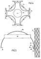
- Figure 3 shows the establishment of a barrier when the support 10 has a step 50.
- the panel P 1 is mounted below the step and the panel P 2 on the step.
- the carpet 12 conforms to the shape of the step.
- the sealing strip 37 between the two panels extends to the lower edge 16 of the P 1 panel which is the lowest.
- the lower portion 37a of the band 37 is therefore facing the "vertical" portion 12a of the carpet.
- a clamping device 52 anchored in the step 50 compresses the lower portion 37a of the band 37 and the vertical portion 12a of the belt between the lower part of the edge of the panel P 1 and the step 50.
- these panels could comprise legs of force 70.
- Figure 4 illustrates the protection of a sewer plate 54.
- the barrier is constituted by four main panels P 3 in the form of a semicircle and four connecting panels P 4 corresponding to a reduced arc.
- FIG. 5 illustrates the fixing of the end of the barrier constituted by the panel P 5 on a wall M: a flat gasket 56 is interposed between the edge 20 of the panel and the wall M and it is clamped between these two surfaces by a angle 58, a bolt 60 and an anchor 62 sealed in the wall.
- the flat gasket is constituted by a strip elastically deformable sealing.
- Figure 6 shows a second embodiment of the fence.
- This second embodiment uses panels P identical to those already described, sealing means lower 12 with the support 10 in accordance with those already described and vertical sealing means also identical.
- each compression system 22 acts on two portions of the same panel
- the compression systems referenced 22 'in Figure 6
- the anchors 24 in the support are of course arranged appropriately.
- the ends of the bars 32 could also be integral or applied on a area located at an intermediate height of the two adjacent panels.
- this second embodiment can also have struts identical to the struts described in connection with FIGS. 1A and 1B.
Abstract
Description
La présente invention a pour objet un dispositif pour la réalisation d'une barrière étanche anti-crue ou anti-inondation sur un support.The subject of the present invention is a device for construction of a flood-proof or flood-proof barrier on a support.
La présente invention concerne des structures individuelles démontables et remontables servant à réaliser temporairement des barrières étanches et utilisables notamment en cas de risque de crue soudaine pour protéger des installations. Plus généralement, cette technique concerne des barrières servant à protéger des sites publics ou privés des effets d'une inondation soudaine venant du débordement d'une étendue ou d'un cours d'eau.The present invention relates to individual structures demountable and reassemblable parts used to temporarily watertight and usable barriers especially in case of flood risk sudden to protect facilities. More generally, this technical barriers are used to protect public or deprived of the effects of a sudden flood coming from the overflow of a stretch or stream.
Différentes techniques sont connues pour réaliser de telles
barrières :
Il existe également les batardeaux réalisés par empilement de profilés métalliques qui sont souvent en aluminium. Ils sont glissés entre des poteaux à section droite en forme de H et viennent reposer sur une surface plane. Le montage de ces batardeaux nécessite souvent un engin de levage pour mettre en place les poteaux, et la mise en place des profilés est relativement longue.There are also cofferdams made by stacking metal profiles that are often made of aluminum. They are slipped between columns with an H-shaped cross-section and come to rest on a flat surface. The assembly of these cofferdams often requires a machine lifting to set up the poles, and the establishment of profiles is relatively long.
Il faut également citer les "bloc-porte".We must also mention the "door-blocks".
Ils consistent à obturer le bas des ouvertures des habitations à protéger. L'étanchéité et la stabilité de ces systèmes sont réalisées en utilisant des joints classiques qui sont comprimés entre une partie scellée en tableau de l'ouverture et une partie amovible.They consist in closing the bottom of the openings of protect. The tightness and stability of these systems are realized in using conventional seals that are compressed between a sealed part in table of the opening and a removable part.
On trouve également des structures gonflables à air ou à eau.There are also inflatable air or water structures.
On trouve aussi des techniques qui utilisent le poids de l'eau. Ces systèmes comportent une large bande de géomembrane qui dépasse du côté inondé. Elle est plaquée au sol par le poids de l'eau dont on veut se protéger. Cette géomembrane est relevée par des palettes inclinées pour assurer la protection contre la crue.There are also techniques that use the weight of water. These systems include a broad band of geomembrane that exceeds on the flooded side. It is pressed to the ground by the weight of the water we want to protect yourself. This geomembrane is raised by inclined pallets to protect against flooding.
On connaít également, par la demande de brevet PCT WO 01/11147, une autre méthode pour réaliser des barrières étanches anti-crue qui consistent à réaliser d'abord dans le sol des moyens d'encastrement réalisés grâce à une boíte de fondation coulée dans le béton qui comporte une rainure. Des panneaux en forme de demi-tuyau réalisés, par exemple, en résine ont leur partie inférieure engagée dans les rainures réalisées dans le bloc de béton. Des montants sont prévus à la jonction entre les panneaux pour réaliser une étanchéité.It is also known from the PCT patent application WO 01/11147, another method for producing watertight barriers anti-flood, which consists of first making the soil installation thanks to a foundation box cast in the concrete that has a groove. Half-pipe shaped panels made, for example, of resin have their lower part engaged in grooves made in the concrete block. Amounts are provided for junction between the panels to achieve a seal.
La présente invention concerne un dispositif pour la réalisation d'une barrière étanche du même type que celui qui est décrit dans la demande de brevet PCT rappelée ci-dessus, mais qui bien sûr n'en présente pas les inconvénients.The present invention relates to a device for carrying out a barrier of the same type as that described in the PCT patent application referred to above, but which of course does not does not have the disadvantages.
Ces inconvénients consistent notamment dans la nécessité de réaliser la rainure dans le support de la barrière pour permettre la fixation des panneaux. En outre, cette rainure doit être réalisée avec une précision suffisante et présenter une profondeur suffisante pour permettre un encastrement effectif des panneaux dans le support. En outre, il est nécessaire que les panneaux présentent une rigidité importante, puisqu'ils ne sont tenus que par leur extrémité inférieure, pour résister aux contraintes appliquées par l'eau. En particulier, l'étanchéité entre le bord inférieur des panneaux engagés dans la rainure et les flancs de la rainure est très difficile à réaliser.These disadvantages include the need to make the groove in the support of the barrier to allow fixation Signs. In addition, this groove must be made with precision sufficient and sufficiently deep to allow effective embedding of the panels in the support. In addition, it is necessary for the panels to have significant rigidity, since they are held only by their lower end, to withstand constraints applied by water. In particular, the seal between the edge lower panels engaged in the groove and flanks of the groove is very difficult to achieve.
Pour atteindre ce but selon l'invention, la barrière étanche
anti-crue réalisée sur un support comprend :
Elle se caractérise en ce qu'elle comprend en outre :
On comprend que chaque panneau est maintenu sur le support par les moyens de compression des panneaux qui sont, d'une part, ancrés dans le support et qui, d'autre part, coopèrent avec chaque panneau. Il en résulte que, grâce à la présence des moyens élastiquement déformables, on obtient de façon sûre et simple une très bonne étanchéité entre le support et l'extrémité inférieure des panneaux. En outre, les panneaux étant mis au moins partiellement en compression, ils présentent une résistance mécanique accrue par rapport à l'eau à contenir et leur maintien vertical est assuré de façon efficace.We understand that each panel is held on the support by the compression means of the panels which are, on the one hand, anchored in the support and which, on the other hand, cooperate with each panel. It results that, thanks to the presence of elastically deformable means, we obtain in a safe and simple way a very good seal between the support and the lower end of the panels. In addition, the panels being at least partially in compression, they exhibit a increased mechanical resistance to the water to be contained and their vertical retention is ensured effectively.
De préférence, les moyens déformables comprennent un tapis disposé sur ledit support.Preferably, the deformable means comprise a carpet disposed on said support.
De préférence, les moyens de mise en compression des panneaux coopèrent avec le bord supérieur des panneaux soumettant ainsi l'ensemble des panneaux à l'effort de compression. Cependant, il est possible que les moyens de compression coopèrent avec une partie intermédiaire des panneaux selon leur direction verticale.Preferably, the means for compressing the panels cooperate with the top edge of the submitting panels thus all the panels to the compressive force. However, it is possible that the compression means cooperate with a part intermediate panels according to their vertical direction.
Quel que soit le mode de mise en oeuvre considéré, les moyens de compression peuvent agir de deux façons différentes sur les panneaux. Soit chaque moyen de compression agit sur deux portions d'un même panneau (de préférence son bord supérieur) ; soit chaque moyen de compression agit sur une portion de deux panneaux adjacents (de préférence leur bord supérieur).Whatever the mode of implementation considered, the means compression can act in two different ways on the panels. Either each compression means acts on two portions of the same panel (preferably its upper edge); either means of compression acts on a portion of two adjacent panels ( preferably their upper edge).
De préférence, les moyens de mise en compression des panneaux comprennent une tige dont l'extrémité inférieure est solidarisable auxdits moyens d'ancrage du support, des moyens de liaison avec ledit panneau, lesdits moyens de liaison coopérant avec la deuxième extrémité de ladite tige, et des moyens coopérant avec les moyens de liaison et l'extrémité supérieure de ladite tige pour exercer un effort de traction sur ladite tige par rapport auxdits moyens de liaison par quoi un effort vertical de compression est appliqué à au moins une partie dudit panneau. Preferably, the means for compressing the panels include a rod whose lower end is solidarisable to said means for anchoring the support, connecting means with said panel, said connecting means cooperating with the second end of said rod, and means cooperating with the means of connection and the upper end of said rod to exert an effort of traction on said rod relative to said connecting means by which a vertical compression force is applied to at least a part of said sign.
On comprend que ces moyens de compression peuvent être mis en place aisément pour assurer le maintien de chaque panneau grâce à la présence des moyens d'ancrage du support.It is understood that these compression means can be put in place easily to ensure the maintenance of each panel through the presence of means for anchoring the support.
De préférence encore, les moyens de liaison comprennent une barre sensiblement horizontale en position active dont les extrémités, en position active, sont solidaires du panneau et qui comporte un trou central dans lequel est engagée l'extrémité supérieure de la tige.More preferably, the connecting means comprise a substantially horizontal bar in active position whose ends, in active position, are integral with the panel and which has a central hole in which is engaged the upper end of the rod.
La barre des moyens de compression peut, de préférence, coopérer en étant en appui sur le bord supérieur du panneau. Cette barre peut également avoir des extrémités solidaires du panneau à sa partie supérieure ou dans une zone intermédiaire.The bar of the compression means can, preferably, cooperate by being in support on the upper edge of the panel. This bar may also have integral ends of the panel at its part superior or in an intermediate zone.
Afin d'améliorer encore la tenue de la barrière, il est possible de prévoir des jambes de force dont l'extrémité supérieure est rendue solidaire des bords verticaux de deux panneaux adjacents et l'extrémité inférieure coopère avec le support , de préférence par l'intermédiaire d'un élément réglable.In order to further improve the behavior of the barrier, it is possible to provide struts whose upper end is rendered secured to the vertical edges of two adjacent panels and the end lower part cooperates with the support, preferably via a adjustable element.
D'autres caractéristiques et avantages de l'invention apparaítront mieux à la lecture de la description qui suit de plusieurs modes de réalisation de l'invention donnés à titre d'exemples non limitatifs. La description se réfère aux figures annexées, sur lesquelles :
- la figure 1 est une vue en perspective simplifiée montrant la réalisation d'une barrière d'étanchéité selon un premier mode de mise en oeuvre ;
- la figure 1A est une vue en perspective d'une variante perfectionnée du premier mode de mise en oeuvre ;
- la figure 1B est une vue en coupe horizontale selon la ligne B-B de la figure 1A ;
- la figure 2 est une vue en coupe verticale partielle montrant la liaison entre deux panneaux et leur fixation sur le support ;
- la figure 2A est une vue partielle montrant le détail A de la figure 2 ;
- la figure 2B est une vue partielle en coupe selon la ligne B-B de la figure 2 ;
- la figure 3 est une vue en coupe verticale montrant la réalisation de la barrière dans le cas où le support comporte une marche ;
- la figure 4 illustre la réalisation d'une barrière pour protéger une plaque d'égout ;
- la figure 5 est une vue de dessus montrant la fixation de l'extrémité de la barrière sur un mur ; et
- la figure 6 est une vue en perspective montrant un deuxième mode de réalisation de la barrière.
- Figure 1 is a simplified perspective view showing the realization of a sealing barrier according to a first embodiment;
- Figure 1A is a perspective view of an improved variant of the first embodiment;
- Figure 1B is a horizontal sectional view along line BB of Figure 1A;
- Figure 2 is a partial vertical sectional view showing the connection between two panels and their attachment to the support;
- Fig. 2A is a partial view showing detail A of Fig. 2;
- Figure 2B is a partial sectional view along line BB of Figure 2;
- Figure 3 is a vertical sectional view showing the embodiment of the barrier in the case where the support comprises a step;
- Figure 4 illustrates the construction of a barrier to protect a sewer plate;
- Figure 5 is a top view showing the attachment of the end of the barrier on a wall; and
- Figure 6 is a perspective view showing a second embodiment of the barrier.
En se référant maintenant aux figures 1 et 2, on va décrire un premier mode de réalisation de la barrière d'étanchéité.Referring now to Figures 1 and 2, we will describe a first embodiment of the sealing barrier.
Sur la figure 1, on a représenté le support 10 qui constitue un
socle pour la réalisation de la barrière proprement dite. Dans le mode de
réalisation décrit en relation avec cette figure, sur la face supérieure du
support 10 est disposé un tapis 12 réalisé en un matériau élastiquement
déformable et étanche qui s'étend sur toute la partie du support sur
laquelle la barrière doit être réalisée. Cependant, d'autres modes de
réalisation de cette étanchéité inférieure seront décrits ultérieurement.FIG. 1 shows the
La barrière proprement dite est constituée par un ensemble de
panneaux P1, P2, etc., qui sont tous identiques dans le mode de
réalisation représenté sur la figure 1. Chaque panneau a la forme d'une
portion de surface cylindrique. En position de montage, chaque panneau P
comporte un bord supérieur 14 et un bord inférieur 16 qui sont de
préférence horizontaux et en forme d'arc de courbe, par exemple en
forme d'arc de cercle, et deux bords rectilignes verticaux 18 et 20. Comme
le montre la figure 1, les panneaux sont montés de telle manière qu'ils
soient juxtaposés par leurs bords verticaux 18 ou 20. Par leur forme,
chaque panneau produit un effet de voûte pour résister à la poussée de
l'eau. De préférence, chaque panneau P, dont la hauteur est sensiblement
égale à celle de la barrière qu'on veut réaliser, est constitué par une seule
pièce. Cela augmente la résistance du panneau et évite les problèmes
d'étanchéité.The barrier itself consists of a set of
panels P1, P2, etc., which are all identical in the mode of
embodiment shown in FIG. 1. Each panel has the form of a
portion of cylindrical surface. In mounting position, each panel P
has an
Dans la description précédente, l'étanchéité entre le bord
inférieur des panneaux et le support est obtenue notamment par la mise
en place du tapis 12 sur le support. Une autre solution consiste dans le
fait que cette étanchéité est réalisée par des éléments d'étanchéité
individuels, chaque élément d'étanchéité, réalisé en un matériau
élastiquement déformable, étant interposé entre le bord inférieur d'un
panneau et le support. Dans ce cas, de préférence, chaque élément
d'étanchéité est solidaire du bord inférieur du panneau. L'élément
d'étanchéité peut se présenter sous la forme d'un joint à section droite en
forme de U monté préalablement sur le bord inférieur du panneau.In the foregoing description, the seal between the edge
inferior panels and the support is obtained in particular by the
in place of the
Pour assurer le montage et le maintien des panneaux P dont les
bords inférieurs 16 reposent sur le tapis 12 ou sur les moyens individuels
d'étanchéité, on utilise des systèmes mécaniques de mise en compression
des panneaux portant la référence générale 22. Pour cela, on réalise dans
le support 10 des éléments d'ancrage tels que 24 de forme convenable.
Bien entendu, au droit de chaque élément d'ancrage 24, le tapis 12,
lorsqu'il existe, comporte une ouverture 26. Cette ouverture peut
également être obtenue par perforation du tapis lors de la mise en place
de celui-ci.To ensure the mounting and the maintenance of the panels P whose
Bien entendu, lorsque chaque panneau est équipé d'une étanchéité inférieure, ce problème n'existe pas.Of course, when each panel is equipped with a Lower seal, this problem does not exist.
Dans une réalisation préférée, du premier mode de réalisation,
chaque système mécanique de compression est constitué par une tige,
verticale en position d'assemblage, référencée 28. A son extrémité
inférieure 28a, la tige 28 est équipée de moyens d'accrochage 30 aptes à
coopérer avec les systèmes d'ancrage 24 dont est équipé le support 10.
Les systèmes mécaniques de compression 22 sont également constitués
par un moyen de liaison avec les panneaux qui est de préférence constitué
par une barre 32 qui coopère avec l'extrémité supérieure 28b de la tige
28. Dans le mode de réalisation représenté sur la figure 1, les barres 32
ont une longueur suffisante pour que leurs extrémités 32a et 32b reposent
sur deux portions du bord supérieur 14 d'un panneau P. Dans sa partie
centrale, la barre 32 comporte un trou 34 pour permettre le passage de
l'extrémité supérieure 28b de la tige 28. Les systèmes mécaniques de
compression comportent en outre des systèmes pour appliquer une
traction aux tiges 28 par rapport aux barres horizontales 32. De
préférence, les systèmes d'application de la traction comprennent d'une
part une portion filetée 35 réalisée à l'extrémité supérieure 28b des tiges
28 et, d'autre part, un écrou 36 coopérant avec cette partie filetée.In a preferred embodiment, of the first embodiment,
each mechanical compression system consists of a rod,
vertical in the assembly position, referenced 28. At its
On comprend qu'en vissant l'écrou 34 sur la partie filetée de la
tige 28, on peut appliquer une traction sur la tige 28 par rapport à la barre
horizontale 32, ce qui induit donc une contrainte de compression verticale
dans le panneau P. D'autres systèmes de traction pourraient être utilisés
tels que des systèmes à excentriques.It is understood that by screwing the
La contrainte de compression qui est appliquée au panneau P
permet, d'une part, d'appliquer avec pression le bord inférieur 16 du
panneau sur le tapis d'étanchéité déformable 12, ou sur les éléments
individuels d'étanchéité, ce qui assure une très bonne étanchéité entre le
panneau et le support 10 et, d'autre part, de soumettre l'ensemble du
panneau P à une contrainte verticale qui en augmente ainsi la résistance
mécanique pour s'opposer à l'effet de la poussée de l'eau. De préférence,
les moyens d'ancrage 24 doivent être situés dans le polygone de
sustentation du panneau. Les moyens peuvent être disposés différemment
dès lors que la résultante de l'effort de compression intercepte le polygone
de sustentation.The compression stress that is applied to the P panel
allows, on the one hand, to apply with pressure the
La barrière d'étanchéité comporte également des systèmes
d'étanchéité entre deux panneaux P juxtaposés représentés plus en détails
sur les figures 2A et 2B. De préférence, ces systèmes d'étanchéité sont
constitués par des bandes verticales 37 élastiquement déformables
interposées entre les bords 18 et 20 de deux panneaux adjacents. Des
systèmes ponctuels de serrage du type par exemple serre-joint 38
assurent le serrage des bords 18 et 20 et donc la compression de la bande
d'étanchéité 36 interposée entre ces bords. On obtient ainsi une très
bonne étanchéité entre deux panneaux juxtaposés. On pourrait utiliser un
unique système de serrage s'étendant sur la plus grande partie de la
hauteur du panneau.The sealing barrier also includes systems
sealing between two juxtaposed panels P shown in more detail
in Figures 2A and 2B. Preferably, these sealing systems are
constituted by
La figure 2B montre un autre exemple de réalisation des
moyens de serrage 38. Ils peuvent être constitués par deux cornières 35
et 39 dont une aile 35a, 39a est appliquée sur les bords 18, 20 des
panneaux et dont l'autre aile 35b, 39b sert à leur fixation mutuelle par
tout moyen convenable.Figure 2B shows another embodiment of
clamping means 38. They can be constituted by two
Comme le montre la figure 2A, de préférence, la bande
d'étanchéité 37 a une extrémité inférieure 37a qui se prolonge un peu au-delà
du bord inférieur 16 des panneaux. Sous l'effet de la compression
appliquée aux panneaux, l'extrémité inférieure 37a de la bande est
écrasée contre le tapis 12 ou contre les extrémités des éléments
individuels d'étanchéité. On réalise ainsi une très bonne étanchéité au
point triple constitué par le support 10 et les bords verticaux 18 et 20 des
panneaux adjacents.As shown in FIG. 2A, preferably the
Il faut ajouter que la liaison entre les bords des panneaux adjacents a également pour effet d'améliorer la tenue mécanique de la barrière puisque les différents panneaux sont solidaires les uns des autres.It must be added that the connection between the edges of the panels adjacent areas also has the effect of improving the mechanical strength of the barrier since the various panels are integral with each other.
Le montage de la barrière d'étanchéité qui vient d'être décrite
en liaison avec les figures 1 et 2 est très simple. Il nécessite simplement
de prévoir dans le support 10 les moyens d'ancrage 24. Les panneaux P
sont mis en place après avoir également mis en place le tapis 12 sur le
support 10 si un tel tapis est prévu. Les panneaux P sont disposés côte à
côte et les bandes d'étanchéité verticales 38 sont interposées entre leurs
bords. A l'aide des systèmes de serrage 38, on réalise la liaison entre les
différents panneaux et l'étanchéité entre ceux-ci.The installation of the sealing barrier which has just been described
in connection with Figures 1 and 2 is very simple. It simply requires
to provide in the
Pour assurer la stabilité de l'ensemble, on met en place les tiges
verticales 28 en accrochant leurs extrémités inférieures au système
d'ancrage 24. On engage l'orifice 34 des barres 32 sur l'extrémité des
tiges 28 en plaçant les extrémités des barres en appui sur le bord
supérieur de chaque panneau de telle manière que la tige 28 soit
verticale. Ensuite, à l'aide de l'écrou 34, on exerce l'effort de traction sur
la tige 28, ce qui induit la compression des panneaux P.To ensure the stability of the whole, we put in place the rods
vertical 28 by hooking their lower ends to the system
anchoring 24. The
Il va de soi qu'on ne sortirait pas de l'invention si l'on utilisait
d'autres systèmes pour appliquer l'effort de traction sur la tige 28 par
rapport aux barres 32. Il va également de soi qu'on ne sortirait pas de
l'invention si les barres 32 étaient rendues solidaires de façon permanente
du panneau P. Il serait également possible de prévoir que les barres 32
solidaires des panneaux P ne soient pas disposées au niveau du bord
supérieur de ces panneaux, mais dans une zone intermédiaire.It goes without saying that we would not go out of the invention if we used
other systems for applying the tensile force on the
La forme de la section droite horizontale des panneaux a bien entendu pour but d'accroítre leur résistance à la poussée exercée par l'eau. Cette section droite est, bien entendu, une courbe qui peut être un demi-cercle ou une courbe approchante pour produire l'effet de voûte.The shape of the horizontal cross-section of the panels has intended to increase their resistance to the thrust exerted by the water. This straight section is, of course, a curve that can be a semicircle or a similar curve to produce the vault effect.
Il faut préciser que, dans le présent texte par "support", il faut
entendre soit le sol lui-même, si sa structure permet la mise en place des
moyens d'ancrage 24 ou une chape en béton ou plus généralement toute
surface sensiblement plane. Cependant, le tapis déformable 12 permet
une adaptation à des supports présentant une surface avec de légères
irrégularités.It should be noted that in the present text "support" requires
hear either the ground itself, if its structure allows the establishment of
anchoring means 24 or a concrete screed or more generally any
substantially flat surface. However, the
Dans certains cas, notamment lorsque les panneaux ont une certaine hauteur, par exemple 2 mètres ou 2,5 mètres, il est souhaitable d'améliorer encore le maintien en position verticale des panneaux qui est obtenu, dans les exemples déjà décrits, uniquement par les moyens de compression.In some cases, especially when the panels have certain height, for example 2 meters or 2.5 meters, it is desirable to further improve the vertical retention of the panels which is obtained, in the examples already described, only by the means of compression.
Pour obtenir ce résultat, on peut ajouter au système déjà décrit des jambes de force, c'est-à-dire ce qu'on a montré sur les figures 1A et 1B.To obtain this result, we can add to the system already described struts, that is to say what has been shown in FIGS. 1A and 1B.
Dans cette variante de réalisation, les moyens de serrage de
deux panneaux adjacents sont de préférence constitués par des fers en U
référencés 39 qui s'étendent sensiblement sur toute la hauteur des
panneaux. Les deux côtés du fer en U 39 sont équipés de vis de serrage
telles que 41, ainsi, la bande d'étanchéité 37 est bien comprimée entre les
bords 18 et 20 des panneaux adjacents.In this variant embodiment, the clamping means of
two adjacent panels are preferably constituted by U-shaped irons
referenced 39 which extend substantially over the entire height of the
panels. Both sides of
Les jambes de force 70 ont une extrémité supérieure 70a qui
est fixée sur le fer en U 39, près de l'extrémité supérieure de celui-ci, et
une extrémité inférieure 70b équipée de préférence d'un moyen réglable
d'appui 72 sur le support 10.The
Pour réaliser certaines configurations de barrières d'étanchéité non rectilignes, il peut être intéressant d'associer aux panneaux standards P des panneaux présentant une section droite différente, par exemple en forme de quart de cercle pour réaliser des angles. Néanmoins, ces panneaux de forme particulière présentent bien sûr la même hauteur que les panneaux standards représentés sur les figures 1 et 1A et les mêmes caractéristiques générales.To realize certain configurations of sealing barriers not rectilinear, it may be interesting to associate with standard panels P panels having a different cross section, for example in quarter-circle shape to make angles. Nevertheless, these particular shaped panels of course have the same height as the standard panels shown in Figures 1 and 1A and the same Main Features.
La figure 3 montre la mise en place d'une barrière lorsque le
support 10 présente une marche 50. Le panneau P1 est monté en dessous
de la marche et le panneau P2 sur la marche.Figure 3 shows the establishment of a barrier when the
Le tapis 12 épouse la forme de la marche. De préférence, la
bande d'étanchéité 37 entre les deux panneaux se prolonge jusqu'au bord
inférieur 16 du panneau P1 qui est le plus bas. La partie inférieure 37a de
la bande 37 est donc en regard de la partie "verticale" 12a du tapis.The
Un dispositif de serrage 52 ancré dans la marche 50 comprime
la partie inférieure 37a de la bande 37 et la partie verticale 12a du tapis
entre la partie inférieure du bord du panneau P1 et la marche 50. Bien
entendu, ces panneaux pourraient comporter des jambes de force 70.A clamping
La figure 4 illustre la protection d'une plaque d'égout 54. La
barrière est constituée par quatre panneaux principaux P3 en forme de
demi-cercle et quatre panneaux de liaison P4 correspondant à un arc de
cercle réduit.Figure 4 illustrates the protection of a
La figure 5 illustre la fixation de l'extrémité de la barrière
constituée par le panneau P5 sur un mur M : un joint plat 56 est interposé
entre le bord 20 du panneau et le mur M et il est serré entre ces deux
surfaces par une cornière 58, un boulon 60 et un ancrage 62 scellé dans
le mur.FIG. 5 illustrates the fixing of the end of the barrier constituted by the panel P 5 on a wall M: a
De préférence, le joint plat est constitué par une bande élastiquement déformable d'étanchéité.Preferably, the flat gasket is constituted by a strip elastically deformable sealing.
La figure 6 montre un deuxième mode de réalisation de la barrière.Figure 6 shows a second embodiment of the fence.
Ce deuxième mode de réalisation utilise des panneaux P
identiques à ceux qui ont déjà été décrits, des moyens d'étanchéité
inférieure 12 avec le support 10 conformes à ceux qui ont déjà été décrits
et des moyens d'étanchéité verticale également identiques.This second embodiment uses panels P
identical to those already described, sealing means
lower 12 with the
Il diffère du premier mode de réalisation par la façon dont les
moyens de compression agissent sur les panneaux. Au lieu que chaque
système de mise en compression 22 agisse sur deux portions d'un même
panneau, les systèmes de mise en compression, référencés 22' sur la
figure 6, agissent chacun sur une portion de deux panneaux adjacents P1
et P2. Les pièces d'ancrage 24 dans le support sont bien sûr disposées de
manière convenable. Les extrémités 32a et 32b de la barre 32 d'un
système de compression 22' sont, dans une version préférée, appliquées
sur une portion 74 (76) des bords supérieurs des panneaux adjacents P1
et P2. Il en va bien sûr de même pour les panneaux P2 et P3, etc..It differs from the first embodiment in the way the compression means act on the panels. Instead of each
Selon ce deuxième mode de réalisation, les extrémités des
barres 32 pourraient également être solidaires ou être appliquées sur une
zone située à une hauteur intermédiaire des deux panneaux adjacents.According to this second embodiment, the ends of the
Il va de soi que ce deuxième mode de réalisation peut également comporter des jambes de force identiques aux jambes de force décrites en liaison avec les figures 1A et 1B.It goes without saying that this second embodiment can also have struts identical to the struts described in connection with FIGS. 1A and 1B.
Claims (20)
Applications Claiming Priority (2)
| Application Number | Priority Date | Filing Date | Title |
|---|---|---|---|
| FR0311355A FR2860250B1 (en) | 2003-09-29 | 2003-09-29 | DEVICE FOR PRODUCING ANTI-CRANE SEALED BARRIER |
| FR0311355 | 2003-09-29 |
Publications (1)
| Publication Number | Publication Date |
|---|---|
| EP1518967A1 true EP1518967A1 (en) | 2005-03-30 |
Family
ID=34178970
Family Applications (1)
| Application Number | Title | Priority Date | Filing Date |
|---|---|---|---|
| EP04292098A Withdrawn EP1518967A1 (en) | 2003-09-29 | 2004-08-27 | Flood barrier |
Country Status (5)
| Country | Link |
|---|---|
| EP (1) | EP1518967A1 (en) |
| AR (1) | AR047221A1 (en) |
| BR (1) | BRPI0404077A (en) |
| CO (1) | CO5580169A1 (en) |
| FR (1) | FR2860250B1 (en) |
Cited By (2)
| Publication number | Priority date | Publication date | Assignee | Title |
|---|---|---|---|---|
| CN107830171A (en) * | 2017-11-09 | 2018-03-23 | 江苏新扬子造船有限公司 | A kind of multisection type dock gate sealing structure and encapsulating method |
| WO2019180231A1 (en) * | 2018-03-23 | 2019-09-26 | Naval Group | Underwater barrier for protecting the environment from disturbances associated with a human activity |
Citations (6)
| Publication number | Priority date | Publication date | Assignee | Title |
|---|---|---|---|---|
| EP0163292A2 (en) * | 1984-06-01 | 1985-12-04 | Ernst Kossbiel | Barrage for high water protection |
| DE19512544C1 (en) * | 1995-04-06 | 1996-07-11 | Trauelsen Hans Joachim | Flood protection wall, which can be dismantled |
| DE19649868A1 (en) * | 1995-11-30 | 1997-06-05 | Wbs Systeme Werner Bank Gmbh | Dam beam arrangement for dam of dike construction |
| EP0924349A2 (en) * | 1997-12-19 | 1999-06-23 | IBS Industriebarrieren Produktions GmbH | Supporting device for fluid protection barrier |
| US5984576A (en) * | 1995-05-16 | 1999-11-16 | Zetzsch; Klaus | Mobile demountable liquid protective wall from horizontally s-shape indented profile elements, which can be stacked on top of each other |
| WO2001011147A1 (en) * | 1999-08-04 | 2001-02-15 | Asio, Spol S R.O. | Anti-flood barrier |
-
2003
- 2003-09-29 FR FR0311355A patent/FR2860250B1/en not_active Expired - Fee Related
-
2004
- 2004-08-27 EP EP04292098A patent/EP1518967A1/en not_active Withdrawn
- 2004-09-22 BR BRPI0404077 patent/BRPI0404077A/en not_active Application Discontinuation
- 2004-09-27 AR ARP040103486A patent/AR047221A1/en unknown
- 2004-09-27 CO CO04095835A patent/CO5580169A1/en not_active Application Discontinuation
Patent Citations (6)
| Publication number | Priority date | Publication date | Assignee | Title |
|---|---|---|---|---|
| EP0163292A2 (en) * | 1984-06-01 | 1985-12-04 | Ernst Kossbiel | Barrage for high water protection |
| DE19512544C1 (en) * | 1995-04-06 | 1996-07-11 | Trauelsen Hans Joachim | Flood protection wall, which can be dismantled |
| US5984576A (en) * | 1995-05-16 | 1999-11-16 | Zetzsch; Klaus | Mobile demountable liquid protective wall from horizontally s-shape indented profile elements, which can be stacked on top of each other |
| DE19649868A1 (en) * | 1995-11-30 | 1997-06-05 | Wbs Systeme Werner Bank Gmbh | Dam beam arrangement for dam of dike construction |
| EP0924349A2 (en) * | 1997-12-19 | 1999-06-23 | IBS Industriebarrieren Produktions GmbH | Supporting device for fluid protection barrier |
| WO2001011147A1 (en) * | 1999-08-04 | 2001-02-15 | Asio, Spol S R.O. | Anti-flood barrier |
Cited By (3)
| Publication number | Priority date | Publication date | Assignee | Title |
|---|---|---|---|---|
| CN107830171A (en) * | 2017-11-09 | 2018-03-23 | 江苏新扬子造船有限公司 | A kind of multisection type dock gate sealing structure and encapsulating method |
| WO2019180231A1 (en) * | 2018-03-23 | 2019-09-26 | Naval Group | Underwater barrier for protecting the environment from disturbances associated with a human activity |
| FR3079339A1 (en) * | 2018-03-23 | 2019-09-27 | Naval Group | UNDERWATER BARRIER PROTECTING THE ENVIRONMENT AGAINST NUISANCES RELATED TO HUMAN ACTIVITY |
Also Published As
| Publication number | Publication date |
|---|---|
| FR2860250B1 (en) | 2006-03-17 |
| AR047221A1 (en) | 2006-01-11 |
| BRPI0404077A (en) | 2005-05-24 |
| FR2860250A1 (en) | 2005-04-01 |
| CO5580169A1 (en) | 2005-11-30 |
Similar Documents
| Publication | Publication Date | Title |
|---|---|---|
| CA2159361C (en) | Raised floor with modular slabs | |
| FR2566814A1 (en) | PREFABRICATED SUPPORT ELEMENTS FOR THE PROTECTION, REINFORCEMENT AND / OR COATING OF EXCAVATIONS, ANCHORING AND ASSEMBLY DEVICES AND METHOD FOR IMPLEMENTING SUCH ELEMENTS AND DEVICES | |
| WO2018015634A1 (en) | Peripheral retention system for a terrace made of slabs | |
| FR2876716A1 (en) | Anti-flood barrier for protecting e.g. public place, has panel units with ends engaged with grooves in vertical posts associated to strut, and pressure applying units exerting pressure on each piling of panel units | |
| EP0606305B1 (en) | Roadway crash barriers comprising at least one horizontal wooden rail | |
| FR2584437A1 (en) | Prefabrication of elements of walls or panels intended for forming the external walls of a building | |
| EP1518967A1 (en) | Flood barrier | |
| FR2962468A1 (en) | DEVICE FOR FIXING THE STRUCTURE OF A SWIMMING POOL | |
| FR2971535A1 (en) | Fence for delimiting field, has posts provided with rabbets, and vertical axis extending parallel to longitudinal axis to authorize adaptation of rabbets to obscuring panel and for angular adjustment between panels | |
| LU84005A1 (en) | FENCE ASSEMBLY | |
| FR2488117A1 (en) | Sectional free-standing display stand - consists of uprights joined by crosspieces, with interlocking hooks and slots, which support vertical panels | |
| EP3006650B1 (en) | Screen device for making a fence and fence without posts made using such a device | |
| FR2739657A1 (en) | Adjustable support frame for fence | |
| FR2928155A1 (en) | Modulable barrier system for protecting building in flood plain, has posts inclinably fixed on base that is installed on ground, reinforcement arms connecting base to each post, and impermeable tarp for covering barrier system | |
| FR2747419A1 (en) | Base for street furniture | |
| FR2874225A1 (en) | Wooden wall for forming above ground enclosure of e.g. swimming pool, has lower girding rails rigidly fixed to slab, and vertical corner posts embedded in upper girding forming sundeck of swimming pool | |
| FR2809428A1 (en) | Wall assembly for swimming pool above ground has two adjacent panels are attached to each end of the attachment plate while the plate has central aperture receiving threaded rod going through the pole | |
| FR2648197A1 (en) | Device for joining wooden elements together to produce a modifiable structure such as, in particular, a shelter against the weather | |
| EP1371784A1 (en) | Formwork especially for producing solid concrete elements | |
| FR2758841A1 (en) | PART FOR FIXING A COATING STABILIZATION MESH | |
| EP1185745B1 (en) | Beam arrangement comprising a linking element for dwelling | |
| EP2871298A1 (en) | Modular system for the construction of buildings, including modules positioned by plates | |
| FR3112155A3 (en) | Railing infill assembly device | |
| EP2674550A1 (en) | Stiffening element for fixing a swimming pool wall, fixing assembly, swimming pool and method of constructing of such a pool | |
| FR3112156A3 (en) | Device, set of parts comprising this device and method of connecting longitudinal elements |
Legal Events
| Date | Code | Title | Description |
|---|---|---|---|
| PUAI | Public reference made under article 153(3) epc to a published international application that has entered the european phase |
Free format text: ORIGINAL CODE: 0009012 |
|
| AK | Designated contracting states |
Kind code of ref document: A1 Designated state(s): AT BE BG CH CY CZ DE DK EE ES FI FR GB GR HU IE IT LI LU MC NL PL PT RO SE SI SK TR |
|
| AX | Request for extension of the european patent |
Extension state: AL HR LT LV MK |
|
| 17P | Request for examination filed |
Effective date: 20050922 |
|
| AKX | Designation fees paid |
Designated state(s): AT BE BG CH CY CZ DE DK EE ES FI FR GB GR HU IE IT LI LU MC NL PL PT RO SE SI SK TR |
|
| RAP1 | Party data changed (applicant data changed or rights of an application transferred) |
Owner name: SOLETANCHE FREYSSINET |
|
| 17Q | First examination report despatched |
Effective date: 20110525 |
|
| STAA | Information on the status of an ep patent application or granted ep patent |
Free format text: STATUS: THE APPLICATION IS DEEMED TO BE WITHDRAWN |
|
| 18D | Application deemed to be withdrawn |
Effective date: 20120106 |