EP1518691A1 - Pufferbehälter für Tintenstrahldrucker - Google Patents
Pufferbehälter für Tintenstrahldrucker Download PDFInfo
- Publication number
- EP1518691A1 EP1518691A1 EP04022507A EP04022507A EP1518691A1 EP 1518691 A1 EP1518691 A1 EP 1518691A1 EP 04022507 A EP04022507 A EP 04022507A EP 04022507 A EP04022507 A EP 04022507A EP 1518691 A1 EP1518691 A1 EP 1518691A1
- Authority
- EP
- European Patent Office
- Prior art keywords
- buffer tank
- ink
- tubular member
- top plate
- hollow needle
- Prior art date
- Legal status (The legal status is an assumption and is not a legal conclusion. Google has not performed a legal analysis and makes no representation as to the accuracy of the status listed.)
- Granted
Links
- 238000004891 communication Methods 0.000 claims abstract description 9
- 229920003002 synthetic resin Polymers 0.000 claims description 8
- 239000000057 synthetic resin Substances 0.000 claims description 8
- 230000005499 meniscus Effects 0.000 description 41
- 230000002829 reductive effect Effects 0.000 description 5
- 230000008901 benefit Effects 0.000 description 3
- 230000000694 effects Effects 0.000 description 3
- 230000002411 adverse Effects 0.000 description 2
- 239000007788 liquid Substances 0.000 description 2
- 230000007246 mechanism Effects 0.000 description 2
- 238000000034 method Methods 0.000 description 2
- 230000004048 modification Effects 0.000 description 2
- 238000012986 modification Methods 0.000 description 2
- 230000008569 process Effects 0.000 description 2
- 238000010926 purge Methods 0.000 description 2
- XLYOFNOQVPJJNP-UHFFFAOYSA-N water Substances O XLYOFNOQVPJJNP-UHFFFAOYSA-N 0.000 description 2
- 241001391944 Commicarpus scandens Species 0.000 description 1
- 230000003247 decreasing effect Effects 0.000 description 1
- 230000006866 deterioration Effects 0.000 description 1
- 238000007599 discharging Methods 0.000 description 1
- 230000008020 evaporation Effects 0.000 description 1
- 238000001704 evaporation Methods 0.000 description 1
- 230000002401 inhibitory effect Effects 0.000 description 1
- 238000004519 manufacturing process Methods 0.000 description 1
- 239000002184 metal Substances 0.000 description 1
- 230000009467 reduction Effects 0.000 description 1
- 230000001105 regulatory effect Effects 0.000 description 1
Images


Classifications
-
- B—PERFORMING OPERATIONS; TRANSPORTING
- B41—PRINTING; LINING MACHINES; TYPEWRITERS; STAMPS
- B41J—TYPEWRITERS; SELECTIVE PRINTING MECHANISMS, i.e. MECHANISMS PRINTING OTHERWISE THAN FROM A FORME; CORRECTION OF TYPOGRAPHICAL ERRORS
- B41J2/00—Typewriters or selective printing mechanisms characterised by the printing or marking process for which they are designed
- B41J2/005—Typewriters or selective printing mechanisms characterised by the printing or marking process for which they are designed characterised by bringing liquid or particles selectively into contact with a printing material
- B41J2/01—Ink jet
- B41J2/17—Ink jet characterised by ink handling
- B41J2/175—Ink supply systems ; Circuit parts therefor
- B41J2/17503—Ink cartridges
- B41J2/17556—Means for regulating the pressure in the cartridge
-
- B—PERFORMING OPERATIONS; TRANSPORTING
- B41—PRINTING; LINING MACHINES; TYPEWRITERS; STAMPS
- B41J—TYPEWRITERS; SELECTIVE PRINTING MECHANISMS, i.e. MECHANISMS PRINTING OTHERWISE THAN FROM A FORME; CORRECTION OF TYPOGRAPHICAL ERRORS
- B41J2/00—Typewriters or selective printing mechanisms characterised by the printing or marking process for which they are designed
- B41J2/005—Typewriters or selective printing mechanisms characterised by the printing or marking process for which they are designed characterised by bringing liquid or particles selectively into contact with a printing material
- B41J2/01—Ink jet
- B41J2/17—Ink jet characterised by ink handling
- B41J2/175—Ink supply systems ; Circuit parts therefor
- B41J2/17566—Ink level or ink residue control
Definitions
- the present invention generally relates to an ink jet printer capable of regulating a back pressure of an ink acting on a nozzle at a substantially constant value, and also to a buffer tank for such a regulation of the back pressure.
- an ink jet printer for performing a printing by ejecting an ink from a nozzle onto a recording medium, a variation in a back pressure of the ink acting on the nozzle, which may be caused by a variation in an amount of the ink in an ink cartridge, adversely affects an accuracy in the ink ejection from the nozzle.
- an ink jet printer is equipped with a mechanism for suppressing the variation in the back pressure of the ink.
- An example of such an ink jet printer (as disclosed in U.S. Patent No. 6702427, for instance) is equipped with a buffer tank in which is held an ink whose surface is maintained substantially at a constant level, to suppress the variation in the back pressure acting on the nozzle.
- This buffer tank is shown in Figs. 7 and 8 and denoted by reference numeral 100.
- the buffer tank 100 has a top plate 104, and an ink inlet needle or hollow needle 102 for drawing an ink I in an ink cartridge 101 into the buffer tank 100, and an air outlet needle or hollow needle 103 for flowing the air out into the ink cartridge 101; the ink inlet and air outlet hollow needles 102, 103 are disposed to extend through the top plate 104.
- the ink inlet hollow needle 102 extends downward farther than the air outlet hollow needle 103, near a bottom of the buffer tank 100.
- each of the hollow needles 102, 103 extends through one of two plug members 106 provided to the ink cartridge 101 when the ink cartridge 101 is attached to the buffer tank 100, each of the hollow needles 102, 103 is formed in a hollow needle-like shape.
- the ink I When the ink I is ejected from the nozzle in this state, the ink I flows out of the buffer tank through an ink outlet 105 formed in a bottom portion of the buffer tank 100 toward the nozzle, with the ink level of the buffer tank 100 lowered.
- the ink surface is separated from the lower end of the air outlet hollow needle 103, with a meniscus being formed around or inside the lower end of the air outlet hollow needle 103.
- the ink surface is further lowered and a head difference reaches a certain value h 0 , the formed meniscus is broken, with the air in the buffer tank 100 flowing out into the ink cartridge 101 through the air outlet hollow needle 103.
- the ink I in the ink cartridge 101 is drawn into the buffer tank 100 through the ink inlet hollow needle 102 in place of the air.
- the ink level of the buffer tank 100 accordingly arises and eventually virtually reaches the lower end of the air outlet hollow needle 103.
- the state where the air in the buffer tank 100 is not allowed to flow out into the ink cartridge 101 is again established, with the flow of the ink I into the buffer tank 100 stopped.
- a meniscus is formed around or inside the air outlet hollow needle, when the ink level is lowered.
- the ink level has been lowered to the level to make the head difference h 0 (a distance between the lower end of the air outlet hollow needle and the ink surface)
- the meniscus is broken at last, allowing the ink to flow into the buffer tank. That is, the ink level of the buffer tank varies by the head difference h 0 .
- the air outlet hollow needle is formed of a narrow, hollow needle-like member, it is inevitable that the head difference ho between the lower end of the air outlet hollow needle and the ink surface which is necessary to break the meniscus is relatively large.
- the variation in the ink level of the buffer tank is relatively large, making it difficult to hold the back pressure of the ink acting on the nozzle substantially constant.
- a head difference h 0 necessary to break a meniscus there may be a case where the meniscus formed at the outer periphery of the air outlet hollow needle can not be broken.
- the ink supplied to the nozzle may include undesirable air bubbles.
- the ink in the ink cartridge flows out or is drawn into the buffer tank via the ink inlet hollow needle which is narrow and extends down to a level near the bottom of the buffer tank. Therefore, the resistance to the flow of the ink flowing into the buffer tank is relatively large. Thus, when the ink level of the buffer tank is lowered upon ejection of the ink from the nozzle which involves the supply of the ink out of the buffer tank, the replenishing the buffer tank with the ink is impeded.
- the resistance to the ink flow is further increased, slowing the replenishing the buffer tank with the ink.
- the ink level can not be immediately restored to the original level (close to the lower end of the air outlet hollow needle), leading to deterioration in the constancy of the ink level which in turn adversely affects the constancy of the back pressure of the ink acting on the nozzle.
- the ink supplied to the nozzle may include air bubbles.
- an object of the present invention is to provide a buffer tank which enables to immediately flow the air out into an ink cartridge and thereby to immediately replenish the buffer tank with an ink when an ink level of the buffer tank is lowered, so that the variation in the ink level of the buffer tank is suppressed to the maximum extent possible.
- the invention provides a buffer tank for an ink jet printer, on whose upper side is attached an ink cartridge containing an ink which is drawn into the buffer tank, and which comprises: a main body having a top plate; an air intake through which air outside the buffer tank is taken into the tank; an air outlet passage comprising at least a part extending in the main body downward from the top plate, so as to flow the air in the tank out into the cartridge; and an ink inlet passage comprising at least a part extending in the main body downward from the top plate, so as to draw the ink in the cartridge into the tank.
- Each of the air outlet and ink inlet passages comprises a hollow needle disposed at the top plate and vertically extends, and at least one of the air outlet and ink inlet passages further comprises a hollow tubular member which extends downward from the top plate and whose inner space is in communication with an inner space of the corresponding hollow needle.
- the air is taken into the buffer tank as a result of supply of the ink from the buffer tank to the nozzle to perform a printing, and is then introduced into the ink cartridge.
- the ink in the ink cartridge is drawn into the buffer tank in place of the air which has flown out into the ink cartridge.
- the tubular member is configured such that the tubular member extends down from the top plate to a level below a lower end of the hollow needle of the air outlet passage and above a lower end of the ink inlet passage, with a cross-sectional area of a hollow of the tubular member at least at a lower end thereof being larger than a cross-sectional area of a hollow of the hollow needle of the air outlet passage.
- the ink surface In the state where the air is not taken into the buffer tank, that is, when there is no ink supply from the buffer tank to the nozzle, a surface of the ink in the buffer tank (which will be hereinafter referred to as "the ink surface") is held still at a level near the lower end of the tubular member which end is located below the lower end of the hollow needle, such that the ink is present inside the tubular member to preclude the air from being introduced into the ink cartridge through the air outlet passage.
- the level of the ink in the buffer tank (which will be referred to as “the ink level of the buffer tank” hereinafter) is lowered, separating the ink surface from the lower end of the tubular member. At this moment, a meniscus is formed around or inside the lower end of the tubular member by the surface tension of the ink. In the state where the meniscus is thus formed, it is impossible to flow out the air through the air outlet passage into the ink cartridge.
- the meniscus is more easily broken by the lowering of the ink level, in other words, the meniscus is broken by a smaller lowering of the ink level, than in the arrangement where the meniscus is formed directly around or inside the air outlet hollow needle.
- the buffer tank may be arranged such that the hollow needle vertically extends through the top plate, and a part of the hollow needle extending below the top plate, in the main body of the buffer tank, is inserted in the tubular member.
- the air in the buffer tank is introduced from the lower end of the tubular member and, in the buffer tank, flows through the hollow needle inserted in the tubular member, to be eventually drawn into the ink cartridge.
- the tubular member is configured such that the tubular member extends down from the top plate to a level below a lower end of the hollow needle of the ink inlet passage and a lower end of the air outlet passage, with a cross-sectional area of a hollow of the tubular member being larger than a cross-sectional area of a hollow of the hollow needle of the ink inlet passage.
- the ink surface is held still at a level near the lower end of the tubular member of the air outlet passage, such that the air is precluded from being introduced into the ink cartridge through the air outlet passage.
- the ink flows through the tubular member whose hollow has a cross-sectional area larger than a cross-sectional area of the hollow of the hollow needle, the resistance to the ink flow is reduced, enabling immediate replenishment of the buffer tank with the ink.
- the variation in the ink level of the buffer tank is thus suppressed to the maximum extent possible, so as to suppress the variation in the pressure of the ink acting on the back side of the nozzle.
- the buffer tank may be arranged such that the hollow needle vertically extend through the top plate, and a part of the hollow needle extending below the top plate, in the main body of the buffer tank, is inserted in the tubular member.
- the ink in the ink cartridge is drawn into the buffer tank through the hollow needle of the ink inlet passage, and, in the buffer tank, flows through the tubular member having a cross-sectional area larger than a cross-sectional area of the hollow needle, where the resistance to the ink flow is reduced.
- each of the air outlet passage and the ink inlet passage comprises the tubular member, such that: the tubular member of the air outlet passage extends down to a level below a lower end of the hollow needle of the air outlet passage, with a cross-sectional area of a hollow of the tubular member at least at a lower end thereof being larger than a cross-sectional area of a hollow of the hollow needle of the air outlet passage; the tubular member of the ink inlet passage extends down to a level below a lower end of the hollow needle of the ink inlet passage, with a cross-sectional area of a hollow the tubular member being larger than a cross-sectional area of a hollow of the hollow needle of the ink inlet passage; and the lower end of the tubular member of the air outlet passage is located above a lower end of the tubular member of the ink inlet passage.
- the air in the buffer tank can be immediately introduced into the ink cartridge by the arrangement of the air outlet passage, and then the ink in the ink cartridge can be accordingly drawn into the buffer tank immediately, again.
- the above mode provides a multiplicative effect in eliminating the delay in replenishing the buffer tank with the ink when the ink in the buffer tank is supplied to the nozzle, and thereby suppresses the variation in the back pressure acting on the nozzle.
- the present invention is also directed to a printer including the buffer tank described above. Such a printer can enjoy the advantages and effects given by the buffer tank.
- an ink jet printer 1 has an ink jet head 2 having nozzles 2a through which an ink I is ejected toward a recording sheet P, an ink cartridge 3 disposed on the upper side of a buffer tank 4 which is connected to the ink jet head 2 via an ink supply tube 8 and accommodates the liquid I flowing in from the ink cartridge 3, a carriage 5 for linearly reciprocating the ink jet head 2 in a direction, a feeding mechanism 6 for feeding the recording sheet P, and a purge device 7 for sucking in air in the ink jet head 2 and the ink I thickened there.
- the ink I is supplied from the buffer tank 4 to which the ink cartridge 3 is attached, via the ink supply tube 8, to the nozzles 2a of the ink jet head 2.
- the ink jet head 2 is reciprocated by the carriage 5 perpendicularly to the feed direction of the recording sheet P while the recording sheet P is fed in the lateral direction in Fig. 1, in which state the ink I is ejected toward the recording sheet P through the nozzle(s) 2a.
- the nozzles 2a are disposed in a position above the liquid level of the ink I in the buffer tank 4.
- the purge device 7 is movable in the directions toward and away from an ink ejecting surface of the ink jet head 2 and has a cap 10 attachable to the ink jet head 2 such that the cap covers the ink ejecting surface, and a suction pump 11 which suctions the ink I from the nozzles 2a. While the ink jet head 2 is out of its printing area (i.e., area where the printing operation is performed on the recording sheet P), it is possible to suck in the air introduced in the ink jet head 2 or the ink I (from which water has evaporated, making the viscosity high) through and from the nozzles 2a by the suction pump 11.
- the ink cartridge 3 has a main body 20 of a synthetic resin for accommodating the ink I, and a cover part 21 made of a synthetic resin and covering the lower side of the main body 20.
- the cover part 21 are formed two insert bores 22 into which an end part of each of an ink inlet hollow needle 36 and an air outlet hollow needle 38, which will be described later, is respectively inserted.
- the main body 20 of the ink cartridge 3 further has two cylindrical parts 23 continuously extending from the upper end of the respective insert bores 22 into the inside of the main body 20.
- the insert bores 22 are press-fitted respective plug members 24 having a resilience for preventing leakage of the ink I.
- the plug members are made of a rubber.
- the buffer tank 4 is for inhibiting variation in the back pressure acting on the ink I at the nozzles 2a, by holding constant the ink level of the buffer tank 4.
- the ink cartridge 3 is attached to the upper side of the buffer tank 4 so that the ink I in the ink cartridge 3 flows into the buffer tank 4.
- the buffer tank 4 has a main body 30 in which is accommodated the ink I and a top plate 31 covering the upper side of the main body 30.
- the main body 30 and the top plate 31 are respectively made of a synthetic resin.
- the buffer tank 4 has an air intake 32 through which the air is introduced into the buffer tank 4.
- an ink outlet 33 In a bottom part of the main body 30 is formed an ink outlet 33, to which is connected the ink supply tube 8.
- the buffer tank 4 has an ink inlet passage 34 and an air outlet passage 35.
- the ink inlet passage 34 is for drawing the ink I in the ink cartridge 3 into the buffer tank 4, while the air outlet passage 35 is for discharging the air which is introduced through the air intake 32 into the buffer tank 4, into the ink cartridge 3.
- the ink inlet passage 34 has an ink inlet hollow needle 36 which extends through the top plate 31, and a tubular member 37 (a second tubular member) which has a cylindrical shape having a diameter larger than that of the ink inlet hollow needle 36 and in which a part of the ink inlet hollow needle 36 which extends below the top plate 31 in the main body 30 is inserted.
- an inner diameter of the ink inlet hollow needle 36 is preferably about 1.2-1.8 mm
- an inner diameter of the tubular member 37 is preferably two times, and more preferably three times, larger than the inner diameter of the ink inlet hollow needle 36.
- the inner diameter of the tubular member 37 is four times larger than the inner diameter of the ink inlet hollow needle 36.
- the air outlet passage 35 has an air outlet hollow needle 38 which extends through the top plate 31, and a tubular member 39 (a first tubular member) which has a cylindrical shape having a diameter larger than that of the air outlet hollow needle 38 and in which a part of the air outlet hollow needle 38 which extends below the top plate 31 in the main body 30 is inserted.
- an inner diameter of the air outlet hollow needle 38 is preferably about 1.2-1.8 mm while an inner diameter of the tubular member 39 is preferably two times, and more preferably three times, larger than the inner diameter of the air outlet hollow needle 38.
- the inner diameter of the tubular member 39 is four times larger than the inner diameter of the air outlet hollow needle 38.
- Each of the ink inlet hollow needle 36 and the air outlet hollow needle 38 is constituted by a hollow needle-like (or cylindrical) member with a pointed end which is made of a metal and has a relatively small diameter.
- the inner diameter of each hollow needle 36, 38 is, for instance, 1.4 mm.
- An upper end part of each hollow needle 36, 38 has an opening 36a, 38a.
- the ink inlet hollow needle 36 and air outlet hollow needle 38 are attached to the top plate 31 such that each of the hollow needles 36, 38 extends slightly below the top plate 31, and lower ends of the hollow needles 36, 38 are located substantially at the same level.
- the ink inlet hollow needle 36 and the air outlet hollow needle 38 can be constituted by an identical hollow needle-like member.
- the conventional buffer tank using two sorts of such hollow needles having respective lengths for the air outlet passage and the ink inlet passage is relatively high in cost.
- an identical member can be employed both as the ink inlet hollow needle 36 and the air outlet hollow needle 38, which reduces the required cost of the components of the buffer tank.
- the two tubular members 37, 39 are formed integrally with the top plate 31 and made of a synthetic resin.
- the tubular member 39 is of circular section and has a diameter larger than that of the air outlet hollow needle 38 (e.g., about 6 mm in inner diameter).
- the cross-sectional area of a hollow of the tubular member 39 is larger than the cross-sectional area of a hollow of the air outlet hollow needle 38.
- the part of the air outlet hollow needle 38 which extends below the top plate 31 into the main body 30 is inserted in the tubular member 39 and thus the inside of the tubular member 39 is in communication with the air outlet hollow needle 38.
- the tubular member 39 extends downward farther than the air outlet hollow needle 38 does. As shown in Figs.
- a part of a circumference of a lower end of the tubular member 39 protrudes downward, forming a protrusion 39a. Accordingly, the distance between the lower end of the tubular member 39 at the part other than the protrusion 39a and the ink surface, and the distance between the protrusion 39a and the ink surface, are different.
- the tubular member 37 is of circular section and has a diameter larger than that of the ink inlet hollow needle 36 (e.g., 6 mm in inner diameter).
- a cross-sectional area of a hollow of the tubular member 37 is larger than a cross-sectional area of a hollow of the ink inlet hollow needle 36.
- the hollow needle-like ink inlet hollow needle 36 and air outlet hollow needle 38 extend through the plug members 24 of the ink cartridge 3, respectively. Where the ink cartridge 3 is disposed above the buffer tank 4, the air flows out into the ink cartridge 3 through the opening 38a of the air outlet hollow needle 38 of the air outlet passage 35. In place of the discharged air, the ink I in the ink cartridge 3 flows into the buffer tank 4 through the opening 36a of the ink inlet hollow needle 36 of the ink inlet passage 34.
- a distance h 1 between the lower end of the tubular member 39 and the lower end of the air outlet hollow needle 38 is set at a value larger than a head difference h 0 (see Fig. 8) necessary to break a meniscus formed at the lower end of the air outlet hollow needle 38 due to the surface tension of the ink I.
- the head difference h 0 is 9 mm; in this case, according to the present embodiment, the distance hi between the lower end of the tubular member 39 and the air outlet hollow needle 38 is made larger than the value of the head difference ho (9 mm), namely, 13 mm.
- a meniscus is initially formed with respect to the outer circumference of the lower end of the tubular member 39, and then with respect to the inner circumference of the lower end of the tubular member 39. That is to say, a meniscus is formed around the lower end of the tubular member 39, namely, at the lower side of an outer periphery of the lower end of the tubular member 39, when the ink level is lowered to a level slightly below the lower end of the tubular member 39 as the ink I in the buffer tank is consumed; when the ink level is further lowered to a level to make the lower end of the tubular member 39 completely off the ink surface, i.e., the meniscus formed at the lower side of the outer periphery of the lower end of the tubular member 39 is broken, there now emerges an upwardly convex meniscus inside the lower end of the tubular member 39.
- the inner diameter of the tubular member 39 is larger (e.g., more than three times larger) than that of the air outlet hollow needle 38, and therefore the head difference necessary to break the meniscus (i.e., the distance between the lower end of the tubular member 39 and the ink surface) is significantly decreased, compared to the case where the meniscus is formed at the lower end of the air outlet hollow needle 38 as in the conventional buffer tank shown in Fig. 8.
- the meniscus inside the lower end of the tubular member 39 or the ink inside the tubular member 39
- the air in the buffer tank 4 flows out into the air outlet hollow needle 38.
- the lower end of the tubular member 39 has the local protrusion 39a projecting downward and it is thereby arranged such that the lower end has the part a distance between which and the ink surface is differentiated from a distance between the other part and the ink surface.
- the ink I inside the tubular member 39 is drawn downward by the surface tension of the ink I along the protrusion 39a, and on the other hand, the air flows into the tubular member 39 from the left side part, as seen in Fig. 2, of the lower end of the tubular member 39.
- the ink I inside the tubular member 39 and the air are instantaneously replaced with each other.
- the air is immediately allowed to flow out into the ink cartridge 3.
- the part of the ink inlet hollow needle 36 extending inside the main body 30 or below the top plate 31 is inserted in the tubular member 37 having a diameter larger than that of the ink inlet hollow needle 36 and extending downward farther than the ink inlet hollow needle 36 does.
- the ink I which is drawn into the buffer tank 4 from the ink cartridge 3 via the ink inlet passage 34, flows through the tubular member 37 of the relatively large diameter in the buffer tank 4, significantly reducing the resistance of the ink draft passage 34 to the flow of the ink I. Therefore, as the air in the buffer tank 4 flows out into the ink cartridge 3, the ink I in the ink cartridge 3 is drawn into the buffer tank 4, immediately replenishing the buffer tank 4 with the ink I.
- the tubular member 39 having a larger diameter than that of the air outlet hollow needle 38 and in communication with the air outlet hollow needle 38 is disposed to extend through the top plate 31 of the buffer tank 4, such that the tubular member 39 extends downward farther than the air outlet hollow needle 38 does.
- a meniscus is not formed at the lower end of the air outlet hollow needle 38 having the relatively small diameter, but is formed at the lower end of the tubular member 39 of the relatively large diameter; the meniscus formed at the lower end of the tubular member 39 of the relatively large diameter is more easily broken than a meniscus formed at the lower end of the air outlet hollow needle 38 of a relatively small diameter.
- the lower end of the tubular member 39 has the local downward protrusion 39a, the balance of the surface tension at the meniscus is easily disrupted, making the break of the meniscus easier. Therefore, when the ink level is slightly lowered, the meniscus formed around or inside the lower end of the tubular member 39 is immediately broken, instantaneously flowing the air out into the ink cartridge 3 via the air outlet passage 35.
- the top plate 31 of the buffer tank 4 is also provided with the tubular member 38 having a diameter larger than that of the ink inlet hollow needle 36 and in communication with the ink inlet hollow needle 36.
- the tubular member 37 extends downward farther than the ink inlet hollow needle 36 does.
- the lower ends of the ink inlet hollow needle 36 and the air outlet hollow needle 38 need not be differentiated in level, but may be located at the same level. Therefore, the ink inlet hollow needle 36 and the air outlet hollow needle 38 can be constituted by an identical member of a hollow needle-like shape, lowering the required cost of components.
- top plate 31 and the tubular members 37, 39 are integrally formed of a synthetic resin, the number of components and steps in the assembly process can be both reduced, lowering the manufacturing cost. It is noted that even where only one of the tubular members 37, 39 is formed integrally with the top plate 31, the same advantage can be enjoyed.
- the shape of the lower end of the tubular member 39 in communication with the air outlet hollow needle 38 is preferably, but not necessarily limited to, that as described above and shown in Fig. 3.
- a lower end surface of the tubular member 39A may be parallel to the ink surface. In this case, the balance of the surface tension at the meniscus is made difficult to be broken and the degree of lowering in the ink level required to break the meniscus is increased, as compared to the arrangement shown in Fig. 3.
- the arrangement of Fig. 4 significantly facilitates breaking the meniscus.
- the process of forming the tubular member 39A is made very easy.
- an arrangement where the lower end of the tubular member 39 has a local part where a distance from the ink surface is different from a distance between the other part and the ink surface, further facilitating the disruption of the balance of the surface tension acting on the lower end of the tubular member, which makes the break of the meniscus easier than in the conventional arrangement shown in Fig 8.
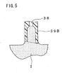
- a lower end surface of the tubular member 39B is inclined with respect to the ink surface by a certain degree, so that the balance of the surface tension of the meniscus is easily disrupted, making it easy to break the meniscus.
- the degree by which the lower end surface of the tubular member 39B is inclined with respect to the ink surface is preferably about 10° to about 20°.
- the top plate 31 and the tubular members 37, 39 may be separately formed from one another.
- the ink inlet hollow needle 36 and the air outlet hollow needle 38 respectively extend through the top plate 31.
- an ink inlet and air outlet hollow needles 36, 38 respectively extend merely upward from, and not below, a top plate 31 of a buffer tank 4C, and are in communication with tubular members 37C, 39C, respectively. In this case, the distance between the lower end of the air outlet hollow needle 38 and the ink surface can be further increased.
- the resistance of the ink inlet passage 34 to the flow of the ink I when flowing into the buffer tank 4C can be further reduced, since the ink I flows only through the tubular member 37C of the relatively large diameter in the buffer tank 4C.
- the tubular member 39 in which the air outlet hollow needle 38 is inserted has, at least at its lower end, a diameter larger than that of the air outlet hollow needle 38. Therefore, the tubular member 39 may be formed in a shape having a diameter which increases toward its lower end, in other words, a trumpet-like shape.
- the tubular members 37, 39 are formed in a cylindrical shape, the tubular members 37, 39 may have other shapes, for instance, a prism which is polygonal in cross section.
- the shape of the cross section of the tubular member 37 may be arbitrarily changed to reduce the resistance of the ink inlet passage 34 to the flow of the ink I drawn into the buffer tank 4, as compared to the conventional arrangement.
- the shape of the cross section of the tubular member 39 may be arbitrarily changed to make it easier to break the meniscus in comparison to the conventional arrangement.
Landscapes
- Ink Jet (AREA)
Applications Claiming Priority (4)
| Application Number | Priority Date | Filing Date | Title |
|---|---|---|---|
| JP2003336045 | 2003-09-26 | ||
| JP2003336044 | 2003-09-26 | ||
| JP2003336044A JP2005103758A (ja) | 2003-09-26 | 2003-09-26 | インクジェットプリンタ及びそのバッファタンク |
| JP2003336045A JP4501389B2 (ja) | 2003-09-26 | 2003-09-26 | インクジェットプリンタ及びそのバッファタンク |
Publications (2)
| Publication Number | Publication Date |
|---|---|
| EP1518691A1 true EP1518691A1 (de) | 2005-03-30 |
| EP1518691B1 EP1518691B1 (de) | 2010-06-23 |
Family
ID=34197266
Family Applications (1)
| Application Number | Title | Priority Date | Filing Date |
|---|---|---|---|
| EP04022507A Active EP1518691B1 (de) | 2003-09-26 | 2004-09-22 | Pufferbehälter für Tintenstrahldrucker |
Country Status (4)
| Country | Link |
|---|---|
| US (1) | US7178908B2 (de) |
| EP (1) | EP1518691B1 (de) |
| AT (1) | ATE471816T1 (de) |
| DE (1) | DE602004027779D1 (de) |
Cited By (1)
| Publication number | Priority date | Publication date | Assignee | Title |
|---|---|---|---|---|
| US5904678A (en) * | 1995-06-19 | 1999-05-18 | Lasersight Technologies, Inc. | Multizone, multipass photorefractive keratectomy |
Families Citing this family (8)
| Publication number | Priority date | Publication date | Assignee | Title |
|---|---|---|---|---|
| US20040086020A1 (en) * | 2002-10-28 | 2004-05-06 | Jordahl Marlow C. | Method and device for detecting altered physical and chemical properties in a liquid environment |
| US20080259137A1 (en) * | 2004-05-13 | 2008-10-23 | Paul Geldenhuys | Ink Supply System for a Printer |
| JP4569507B2 (ja) * | 2006-03-31 | 2010-10-27 | ブラザー工業株式会社 | インクジェット記録装置 |
| JP4817954B2 (ja) * | 2006-05-02 | 2011-11-16 | キヤノン株式会社 | インクジェット記録装置 |
| JP4877213B2 (ja) * | 2007-11-30 | 2012-02-15 | ブラザー工業株式会社 | 液滴噴射装置 |
| US8931887B2 (en) * | 2012-01-13 | 2015-01-13 | Seiko Epson Corporation | Liquid consumption apparatus, liquid supply member, and liquid supply system |
| EP2907665B1 (de) | 2012-01-13 | 2017-11-29 | Seiko Epson Corporation | Kartusche mit Endgeräteanschlussstruktur |
| JP7183777B2 (ja) * | 2018-12-25 | 2022-12-06 | ブラザー工業株式会社 | 液体供給システム |
Citations (3)
| Publication number | Priority date | Publication date | Assignee | Title |
|---|---|---|---|---|
| EP1232871A1 (de) * | 2001-02-09 | 2002-08-21 | Canon Kabushiki Kaisha | Flüssigkeitsbehälter und Aufzeichnungsgerät |
| EP1273451A2 (de) * | 2001-07-03 | 2003-01-08 | Eastman Kodak Company | Grossvolumen-Tintenversorgungssystem |
| US6561637B2 (en) * | 2001-07-06 | 2003-05-13 | Brother Kogyo Kabushiki Kaisha | Ink jet head having buffer tank in fluid communication with ink circulation pathway |
Family Cites Families (8)
| Publication number | Priority date | Publication date | Assignee | Title |
|---|---|---|---|---|
| JPS5656877A (en) * | 1979-10-17 | 1981-05-19 | Canon Inc | Ink jet recording apparatus |
| JP3450643B2 (ja) * | 1996-04-25 | 2003-09-29 | キヤノン株式会社 | 液体収容容器への液体補充方法、該補充方法を用いる液体吐出記録装置、液体補充容器、液体収容容器およびヘッドカートリッジ |
| US5905518A (en) * | 1998-04-29 | 1999-05-18 | Hewlett-Packard Company | One shot air purge for replaceable ink supply |
| JP3437491B2 (ja) * | 1998-06-30 | 2003-08-18 | キヤノン株式会社 | インク注入方法、それが用いられるインク注入装置、および、それを備えるインクジェット記録装置 |
| JP2001187459A (ja) * | 1999-12-28 | 2001-07-10 | Fuji Xerox Co Ltd | インクジェット記録装置 |
| JP3667284B2 (ja) | 2001-02-09 | 2005-07-06 | キヤノン株式会社 | 液体収納容器および記録装置 |
| JP2002234180A (ja) * | 2001-02-09 | 2002-08-20 | Canon Inc | インク供給装置、インク供給機構およびインクジェット記録装置 |
| JP4193435B2 (ja) * | 2002-07-23 | 2008-12-10 | ブラザー工業株式会社 | インクカートリッジ、および、そのインク充填方法 |
-
2004
- 2004-08-26 US US10/926,867 patent/US7178908B2/en active Active
- 2004-09-22 AT AT04022507T patent/ATE471816T1/de not_active IP Right Cessation
- 2004-09-22 DE DE602004027779T patent/DE602004027779D1/de active Active
- 2004-09-22 EP EP04022507A patent/EP1518691B1/de active Active
Patent Citations (4)
| Publication number | Priority date | Publication date | Assignee | Title |
|---|---|---|---|---|
| EP1232871A1 (de) * | 2001-02-09 | 2002-08-21 | Canon Kabushiki Kaisha | Flüssigkeitsbehälter und Aufzeichnungsgerät |
| US6702427B2 (en) | 2001-02-09 | 2004-03-09 | Canon Kabushiki Kaisha | Liquid container and recording apparatus |
| EP1273451A2 (de) * | 2001-07-03 | 2003-01-08 | Eastman Kodak Company | Grossvolumen-Tintenversorgungssystem |
| US6561637B2 (en) * | 2001-07-06 | 2003-05-13 | Brother Kogyo Kabushiki Kaisha | Ink jet head having buffer tank in fluid communication with ink circulation pathway |
Cited By (1)
| Publication number | Priority date | Publication date | Assignee | Title |
|---|---|---|---|---|
| US5904678A (en) * | 1995-06-19 | 1999-05-18 | Lasersight Technologies, Inc. | Multizone, multipass photorefractive keratectomy |
Also Published As
| Publication number | Publication date |
|---|---|
| DE602004027779D1 (de) | 2010-08-05 |
| ATE471816T1 (de) | 2010-07-15 |
| US7178908B2 (en) | 2007-02-20 |
| EP1518691B1 (de) | 2010-06-23 |
| US20050068388A1 (en) | 2005-03-31 |
Similar Documents
| Publication | Publication Date | Title |
|---|---|---|
| TWI429542B (zh) | 具有回收墨水及壓力等化上游與下游墨水線的印表機 | |
| US7360876B2 (en) | Liquid supply system, fluid communicating structure, ink supply system, and inkjet recording head utilizing the fluid communicating structure | |
| US7699452B2 (en) | Ink cartridge and method of ink injection thereinto | |
| CA2386730C (en) | Ink cartridge and method of ink injection thereinto | |
| JP4882461B2 (ja) | フィルター装置及び液滴吐出装置 | |
| EP3263343B1 (de) | Flüssigkeitsabgabevorrichtung und zwischenhalterungskörper | |
| KR100447849B1 (ko) | 공기유입 시점이 일정한 잉크 카트리지 | |
| EP1518691B1 (de) | Pufferbehälter für Tintenstrahldrucker | |
| US11833829B2 (en) | Inkjet printing apparatus and ink tank | |
| CN110549743A (zh) | 墨盒结构、注墨方法及其打印机 | |
| JP4018577B2 (ja) | インクジェット記録ヘッドカートリッジ | |
| JP2011178013A (ja) | 液体噴射装置 | |
| JP2013111967A (ja) | 液体タンクおよび液体噴射装置 | |
| JP5332431B2 (ja) | 液体供給装置、印刷装置及び液体供給装置の制御方法 | |
| JP2002086748A (ja) | サブタンクとインク供給装置及びインクジェット記録装置 | |
| JP3973822B2 (ja) | インク供給装置及びそれを使用した画像形成装置 | |
| CN211280255U (zh) | 墨盒结构及其打印机 | |
| JP2012096502A (ja) | 液体噴射装置 | |
| JP4501389B2 (ja) | インクジェットプリンタ及びそのバッファタンク | |
| JP2005103758A (ja) | インクジェットプリンタ及びそのバッファタンク | |
| US11833833B2 (en) | Liquid container and liquid ejection apparatus | |
| JP2004142463A (ja) | インクカートリッジ | |
| JP2006168224A (ja) | バルブユニット及び同バルブユニットを備えた液体噴射装置 | |
| JPH1191130A (ja) | インクジェットプリンタ | |
| JP2012101460A (ja) | 液体噴射装置 |
Legal Events
| Date | Code | Title | Description |
|---|---|---|---|
| PUAI | Public reference made under article 153(3) epc to a published international application that has entered the european phase |
Free format text: ORIGINAL CODE: 0009012 |
|
| AK | Designated contracting states |
Kind code of ref document: A1 Designated state(s): AT BE BG CH CY CZ DE DK EE ES FI FR GB GR HU IE IT LI LU MC NL PL PT RO SE SI SK TR |
|
| AX | Request for extension of the european patent |
Extension state: AL HR LT LV MK |
|
| 17P | Request for examination filed |
Effective date: 20050728 |
|
| AKX | Designation fees paid |
Designated state(s): AT BE BG CH CY CZ DE DK EE ES FI FR GB GR HU IE IT LI LU MC NL PL PT RO SE SI SK TR |
|
| 17Q | First examination report despatched |
Effective date: 20070724 |
|
| GRAP | Despatch of communication of intention to grant a patent |
Free format text: ORIGINAL CODE: EPIDOSNIGR1 |
|
| GRAS | Grant fee paid |
Free format text: ORIGINAL CODE: EPIDOSNIGR3 |
|
| GRAA | (expected) grant |
Free format text: ORIGINAL CODE: 0009210 |
|
| AK | Designated contracting states |
Kind code of ref document: B1 Designated state(s): AT BE BG CH CY CZ DE DK EE ES FI FR GB GR HU IE IT LI LU MC NL PL PT RO SE SI SK TR |
|
| REG | Reference to a national code |
Ref country code: CH Ref legal event code: EP |
|
| REG | Reference to a national code |
Ref country code: IE Ref legal event code: FG4D |
|
| REF | Corresponds to: |
Ref document number: 602004027779 Country of ref document: DE Date of ref document: 20100805 Kind code of ref document: P |
|
| REG | Reference to a national code |
Ref country code: NL Ref legal event code: VDEP Effective date: 20100623 |
|
| PG25 | Lapsed in a contracting state [announced via postgrant information from national office to epo] |
Ref country code: SE Free format text: LAPSE BECAUSE OF FAILURE TO SUBMIT A TRANSLATION OF THE DESCRIPTION OR TO PAY THE FEE WITHIN THE PRESCRIBED TIME-LIMIT Effective date: 20100623 |
|
| PG25 | Lapsed in a contracting state [announced via postgrant information from national office to epo] |
Ref country code: FI Free format text: LAPSE BECAUSE OF FAILURE TO SUBMIT A TRANSLATION OF THE DESCRIPTION OR TO PAY THE FEE WITHIN THE PRESCRIBED TIME-LIMIT Effective date: 20100623 Ref country code: AT Free format text: LAPSE BECAUSE OF FAILURE TO SUBMIT A TRANSLATION OF THE DESCRIPTION OR TO PAY THE FEE WITHIN THE PRESCRIBED TIME-LIMIT Effective date: 20100623 Ref country code: SI Free format text: LAPSE BECAUSE OF FAILURE TO SUBMIT A TRANSLATION OF THE DESCRIPTION OR TO PAY THE FEE WITHIN THE PRESCRIBED TIME-LIMIT Effective date: 20100623 |
|
| PG25 | Lapsed in a contracting state [announced via postgrant information from national office to epo] |
Ref country code: PL Free format text: LAPSE BECAUSE OF FAILURE TO SUBMIT A TRANSLATION OF THE DESCRIPTION OR TO PAY THE FEE WITHIN THE PRESCRIBED TIME-LIMIT Effective date: 20100623 Ref country code: GR Free format text: LAPSE BECAUSE OF FAILURE TO SUBMIT A TRANSLATION OF THE DESCRIPTION OR TO PAY THE FEE WITHIN THE PRESCRIBED TIME-LIMIT Effective date: 20100924 |
|
| PG25 | Lapsed in a contracting state [announced via postgrant information from national office to epo] |
Ref country code: EE Free format text: LAPSE BECAUSE OF FAILURE TO SUBMIT A TRANSLATION OF THE DESCRIPTION OR TO PAY THE FEE WITHIN THE PRESCRIBED TIME-LIMIT Effective date: 20100623 Ref country code: NL Free format text: LAPSE BECAUSE OF FAILURE TO SUBMIT A TRANSLATION OF THE DESCRIPTION OR TO PAY THE FEE WITHIN THE PRESCRIBED TIME-LIMIT Effective date: 20100623 |
|
| PG25 | Lapsed in a contracting state [announced via postgrant information from national office to epo] |
Ref country code: CY Free format text: LAPSE BECAUSE OF FAILURE TO SUBMIT A TRANSLATION OF THE DESCRIPTION OR TO PAY THE FEE WITHIN THE PRESCRIBED TIME-LIMIT Effective date: 20100623 Ref country code: CZ Free format text: LAPSE BECAUSE OF FAILURE TO SUBMIT A TRANSLATION OF THE DESCRIPTION OR TO PAY THE FEE WITHIN THE PRESCRIBED TIME-LIMIT Effective date: 20100623 Ref country code: PT Free format text: LAPSE BECAUSE OF FAILURE TO SUBMIT A TRANSLATION OF THE DESCRIPTION OR TO PAY THE FEE WITHIN THE PRESCRIBED TIME-LIMIT Effective date: 20101025 Ref country code: RO Free format text: LAPSE BECAUSE OF FAILURE TO SUBMIT A TRANSLATION OF THE DESCRIPTION OR TO PAY THE FEE WITHIN THE PRESCRIBED TIME-LIMIT Effective date: 20100623 Ref country code: SK Free format text: LAPSE BECAUSE OF FAILURE TO SUBMIT A TRANSLATION OF THE DESCRIPTION OR TO PAY THE FEE WITHIN THE PRESCRIBED TIME-LIMIT Effective date: 20100623 Ref country code: BE Free format text: LAPSE BECAUSE OF FAILURE TO SUBMIT A TRANSLATION OF THE DESCRIPTION OR TO PAY THE FEE WITHIN THE PRESCRIBED TIME-LIMIT Effective date: 20100623 |
|
| PG25 | Lapsed in a contracting state [announced via postgrant information from national office to epo] |
Ref country code: IT Free format text: LAPSE BECAUSE OF FAILURE TO SUBMIT A TRANSLATION OF THE DESCRIPTION OR TO PAY THE FEE WITHIN THE PRESCRIBED TIME-LIMIT Effective date: 20100623 |
|
| PG25 | Lapsed in a contracting state [announced via postgrant information from national office to epo] |
Ref country code: DK Free format text: LAPSE BECAUSE OF FAILURE TO SUBMIT A TRANSLATION OF THE DESCRIPTION OR TO PAY THE FEE WITHIN THE PRESCRIBED TIME-LIMIT Effective date: 20100623 Ref country code: MC Free format text: LAPSE BECAUSE OF NON-PAYMENT OF DUE FEES Effective date: 20100930 |
|
| PLBE | No opposition filed within time limit |
Free format text: ORIGINAL CODE: 0009261 |
|
| REG | Reference to a national code |
Ref country code: CH Ref legal event code: PL |
|
| STAA | Information on the status of an ep patent application or granted ep patent |
Free format text: STATUS: NO OPPOSITION FILED WITHIN TIME LIMIT |
|
| 26N | No opposition filed |
Effective date: 20110324 |
|
| REG | Reference to a national code |
Ref country code: DE Ref legal event code: R097 Ref document number: 602004027779 Country of ref document: DE Effective date: 20110323 |
|
| PG25 | Lapsed in a contracting state [announced via postgrant information from national office to epo] |
Ref country code: LI Free format text: LAPSE BECAUSE OF NON-PAYMENT OF DUE FEES Effective date: 20100930 Ref country code: IE Free format text: LAPSE BECAUSE OF NON-PAYMENT OF DUE FEES Effective date: 20100922 Ref country code: CH Free format text: LAPSE BECAUSE OF NON-PAYMENT OF DUE FEES Effective date: 20100930 |
|
| PG25 | Lapsed in a contracting state [announced via postgrant information from national office to epo] |
Ref country code: BG Free format text: LAPSE BECAUSE OF FAILURE TO SUBMIT A TRANSLATION OF THE DESCRIPTION OR TO PAY THE FEE WITHIN THE PRESCRIBED TIME-LIMIT Effective date: 20100623 Ref country code: LU Free format text: LAPSE BECAUSE OF NON-PAYMENT OF DUE FEES Effective date: 20100922 Ref country code: HU Free format text: LAPSE BECAUSE OF FAILURE TO SUBMIT A TRANSLATION OF THE DESCRIPTION OR TO PAY THE FEE WITHIN THE PRESCRIBED TIME-LIMIT Effective date: 20101224 |
|
| PG25 | Lapsed in a contracting state [announced via postgrant information from national office to epo] |
Ref country code: TR Free format text: LAPSE BECAUSE OF FAILURE TO SUBMIT A TRANSLATION OF THE DESCRIPTION OR TO PAY THE FEE WITHIN THE PRESCRIBED TIME-LIMIT Effective date: 20100623 |
|
| PG25 | Lapsed in a contracting state [announced via postgrant information from national office to epo] |
Ref country code: BG Free format text: LAPSE BECAUSE OF FAILURE TO SUBMIT A TRANSLATION OF THE DESCRIPTION OR TO PAY THE FEE WITHIN THE PRESCRIBED TIME-LIMIT Effective date: 20100923 |
|
| PG25 | Lapsed in a contracting state [announced via postgrant information from national office to epo] |
Ref country code: ES Free format text: LAPSE BECAUSE OF FAILURE TO SUBMIT A TRANSLATION OF THE DESCRIPTION OR TO PAY THE FEE WITHIN THE PRESCRIBED TIME-LIMIT Effective date: 20101004 |
|
| REG | Reference to a national code |
Ref country code: FR Ref legal event code: PLFP Year of fee payment: 13 |
|
| REG | Reference to a national code |
Ref country code: FR Ref legal event code: PLFP Year of fee payment: 14 |
|
| REG | Reference to a national code |
Ref country code: FR Ref legal event code: PLFP Year of fee payment: 15 |
|
| PGFP | Annual fee paid to national office [announced via postgrant information from national office to epo] |
Ref country code: FR Payment date: 20200814 Year of fee payment: 17 Ref country code: GB Payment date: 20200828 Year of fee payment: 17 |
|
| GBPC | Gb: european patent ceased through non-payment of renewal fee |
Effective date: 20210922 |
|
| PG25 | Lapsed in a contracting state [announced via postgrant information from national office to epo] |
Ref country code: GB Free format text: LAPSE BECAUSE OF NON-PAYMENT OF DUE FEES Effective date: 20210922 Ref country code: FR Free format text: LAPSE BECAUSE OF NON-PAYMENT OF DUE FEES Effective date: 20210930 |
|
| PGFP | Annual fee paid to national office [announced via postgrant information from national office to epo] |
Ref country code: DE Payment date: 20230808 Year of fee payment: 20 |