EP1518642A2 - Vorrichtung zum Randformen von Kacheln oder Platten - Google Patents
Vorrichtung zum Randformen von Kacheln oder Platten Download PDFInfo
- Publication number
- EP1518642A2 EP1518642A2 EP04077146A EP04077146A EP1518642A2 EP 1518642 A2 EP1518642 A2 EP 1518642A2 EP 04077146 A EP04077146 A EP 04077146A EP 04077146 A EP04077146 A EP 04077146A EP 1518642 A2 EP1518642 A2 EP 1518642A2
- Authority
- EP
- European Patent Office
- Prior art keywords
- slide
- motor
- machine
- workpiece
- frame
- Prior art date
- Legal status (The legal status is an assumption and is not a legal conclusion. Google has not performed a legal analysis and makes no representation as to the accuracy of the status listed.)
- Withdrawn
Links
Images
Classifications
-
- B—PERFORMING OPERATIONS; TRANSPORTING
- B24—GRINDING; POLISHING
- B24B—MACHINES, DEVICES, OR PROCESSES FOR GRINDING OR POLISHING; DRESSING OR CONDITIONING OF ABRADING SURFACES; FEEDING OF GRINDING, POLISHING, OR LAPPING AGENTS
- B24B41/00—Component parts such as frames, beds, carriages, headstocks
- B24B41/06—Work supports, e.g. adjustable steadies
- B24B41/068—Table-like supports for panels, sheets or the like
-
- B—PERFORMING OPERATIONS; TRANSPORTING
- B24—GRINDING; POLISHING
- B24B—MACHINES, DEVICES, OR PROCESSES FOR GRINDING OR POLISHING; DRESSING OR CONDITIONING OF ABRADING SURFACES; FEEDING OF GRINDING, POLISHING, OR LAPPING AGENTS
- B24B7/00—Machines or devices designed for grinding plane surfaces on work, including polishing plane glass surfaces; Accessories therefor
- B24B7/20—Machines or devices designed for grinding plane surfaces on work, including polishing plane glass surfaces; Accessories therefor characterised by a special design with respect to properties of the material of non-metallic articles to be ground
- B24B7/22—Machines or devices designed for grinding plane surfaces on work, including polishing plane glass surfaces; Accessories therefor characterised by a special design with respect to properties of the material of non-metallic articles to be ground for grinding inorganic material, e.g. stone, ceramics, porcelain
-
- B—PERFORMING OPERATIONS; TRANSPORTING
- B24—GRINDING; POLISHING
- B24B—MACHINES, DEVICES, OR PROCESSES FOR GRINDING OR POLISHING; DRESSING OR CONDITIONING OF ABRADING SURFACES; FEEDING OF GRINDING, POLISHING, OR LAPPING AGENTS
- B24B9/00—Machines or devices designed for grinding edges or bevels on work or for removing burrs; Accessories therefor
- B24B9/02—Machines or devices designed for grinding edges or bevels on work or for removing burrs; Accessories therefor characterised by a special design with respect to properties of materials specific to articles to be ground
- B24B9/06—Machines or devices designed for grinding edges or bevels on work or for removing burrs; Accessories therefor characterised by a special design with respect to properties of materials specific to articles to be ground of non-metallic inorganic material, e.g. stone, ceramics, porcelain
Definitions
- the invention is usefully applicable in edging pieces of tiles or slabs, previously cut from ceramic tiles or slabs destined, for example, to be used as skirting board.
- the edging is usually a rounded bevelling.
- the main aim of the present invention is to obviate the limitations and drawbacks in the prior art by making available, directly in the work-site or the laying site, a machine for shaping edges of tiles or slabs and/or special elements made from the former.
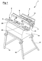
- 1 denotes in its entirety a frame having legs 10 for resting on the ground.
- a work plane 2 is supported on the frame 1, which work plane 2 is inclined with respect to the vertical, along which a workpiece slide 3 moves; the workpiece slide 3 feeds the workpiece to the machine.
- the frame 1 and the legs 10 are predisposed so that when the legs 10 rest on a horizontal surface, the angle of inclination P of the work plane 2 with respect to the vertical is of about 60° and the direction of motion of the workpiece slide 3 is horizontal.
- the workpiece slide 3 is provided with a handle 13 for translating in a horizontal direction and is provided with a blocking organ i.e. a lever 23 which blocks the workpiece 11 to the slide or the table; in the embodiment the workpiece 11 is a special element, previously cut away from a tile or slab.
- a blocking organ i.e. a lever 23 which blocks the workpiece 11 to the slide or the table; in the embodiment the workpiece 11 is a special element, previously cut away from a tile or slab.
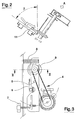
- a motor head 4 is constrained on a portion of the frame 1 arranged at 90° to the work plane 2.
- the motor head 4 bears a tool-bearing chuck as well as the motor itself, and the transmission for the motor.
- the motor head 4 is supported on a motor slide 5, to which it is hinged by a pivot 6 having an axis which is perpendicular to the work plane 2.
- the motor slide 5 is coupled to the frame 1 and can be translated and adjusted regarding its position with the frame 1 in a perpendicular direction to the work plane 2.
- the adjustment of the position of the motor slide 5 is made possible by the predisposing of a screw device 12 of known type, which is easily manoeuvrable from outside and enables achievement of a precise positioning along the direction of the tool-bearing chuck on the motor head 4, and therefore a precise positioning also of the tool in the chuck.
- the tool-bearing chuck is made to bear a cutting tool which in the preferred embodiment is a grinder 9.
- the whole motor head 4 is mobile in rotation about the pivot 6, so that an angular position thereof can be adjusted.
- the position is determined by a screw 7, operating between the frame 1 and the motor head 4, which screw 7 acts against elastic means 8, also operating between the frame 1 and the motor head 4.
- the screw 7 is used to adjust the position of the grinder 9 in a perpendicular direction to the workpiece slide 3 motion direction, and a parallel direction to the work plane 2. Adjustment of the position of the grinder 9 in a parallel direction to the rotation axis of the grinder 9 and perpendicular to the workpiece slide 3 and the work plane 2 is done by adjusting the motor slide 5.
- the grinder 9 is powered in the cutting direction, while the in-feeding of the workpiece 11 is done manually using the handle 13, with the workpiece 11 blocked on the workpiece slide 3.
- the inclination to the vertical of the work plane 2 means that the work can be done very simply, as the force of gravity is used to achieve a correct reference orientation of the workpiece 11 with respect to the grinder 9.
- the inclination further enables the cutting liquid (water) to be easily collected, as it falls by gravity into the underlying tray 14 fixed to the frame 1.
Landscapes
- Engineering & Computer Science (AREA)
- Mechanical Engineering (AREA)
- Chemical & Material Sciences (AREA)
- Ceramic Engineering (AREA)
- Inorganic Chemistry (AREA)
- Finish Polishing, Edge Sharpening, And Grinding By Specific Grinding Devices (AREA)
- Devices For Post-Treatments, Processing, Supply, Discharge, And Other Processes (AREA)
- Jigs For Machine Tools (AREA)
- Processing Of Stones Or Stones Resemblance Materials (AREA)
Applications Claiming Priority (2)
| Application Number | Priority Date | Filing Date | Title |
|---|---|---|---|
| ITMI20030261 | 2003-09-25 | ||
| ITMO20030261 ITMO20030261A1 (it) | 2003-09-25 | 2003-09-25 | Macchina per la sagomatura di bordi di piastrelle o lastre. |
Publications (2)
| Publication Number | Publication Date |
|---|---|
| EP1518642A2 true EP1518642A2 (de) | 2005-03-30 |
| EP1518642A3 EP1518642A3 (de) | 2006-01-18 |
Family
ID=34179338
Family Applications (1)
| Application Number | Title | Priority Date | Filing Date |
|---|---|---|---|
| EP04077146A Withdrawn EP1518642A3 (de) | 2003-09-25 | 2004-08-02 | Vorrichtung zum Randformen von Kacheln oder Platten |
Country Status (2)
| Country | Link |
|---|---|
| EP (1) | EP1518642A3 (de) |
| IT (1) | ITMO20030261A1 (de) |
Cited By (2)
| Publication number | Priority date | Publication date | Assignee | Title |
|---|---|---|---|---|
| US8597080B2 (en) | 2003-09-24 | 2013-12-03 | Inland Diamond Products Company | Ophthalmic roughing wheel |
| USD697117S1 (en) | 2004-04-22 | 2014-01-07 | Inland Diamond Products Company | Ophthalmic roughing wheel |
Family Cites Families (5)
| Publication number | Priority date | Publication date | Assignee | Title |
|---|---|---|---|---|
| BE506447A (de) * | 1950-10-18 | |||
| FR2703286B1 (fr) * | 1993-04-02 | 1995-06-30 | Rocamat Saone Rhone | Procede d'usinage des chants de dalles de pierre et appareil le mettant en oeuvre. |
| US5947103A (en) * | 1998-01-05 | 1999-09-07 | Saccon; Lorenzo | Stone tile finishing system |
| FR2794397B1 (fr) * | 1999-06-02 | 2001-09-28 | Rocamat Pierre Naturelle | Banc de faconnage et procede de vieillissement simule d'une dalle de pierre |
| DE20006752U1 (de) * | 2000-04-12 | 2000-06-15 | Schindler Steinbearbeitungsmaschinen-Anlagentechnik Gmbh, 93057 Regensburg | Fasenbearbeitungsmaschine für Steinplatten |
-
2003
- 2003-09-25 IT ITMO20030261 patent/ITMO20030261A1/it unknown
-
2004
- 2004-08-02 EP EP04077146A patent/EP1518642A3/de not_active Withdrawn
Cited By (2)
| Publication number | Priority date | Publication date | Assignee | Title |
|---|---|---|---|---|
| US8597080B2 (en) | 2003-09-24 | 2013-12-03 | Inland Diamond Products Company | Ophthalmic roughing wheel |
| USD697117S1 (en) | 2004-04-22 | 2014-01-07 | Inland Diamond Products Company | Ophthalmic roughing wheel |
Also Published As
| Publication number | Publication date |
|---|---|
| EP1518642A3 (de) | 2006-01-18 |
| ITMO20030261A1 (it) | 2005-03-26 |
Similar Documents
| Publication | Publication Date | Title |
|---|---|---|
| CN202462654U (zh) | 一种多功能瓷砖切割机 | |
| US20080110311A1 (en) | Multiple-tool machine for combined cutting of slabs of hard material | |
| US10246837B2 (en) | Method and apparatus for cutting linear trenches in concrete | |
| CN101318354A (zh) | 具有可松开工具的瓷砖锯 | |
| US7037182B2 (en) | Template device for the control of the movements of diamond milling cutters or the like, to be mounted on marble or stone slab border polishing machines | |
| US7198042B2 (en) | Apparatus for cutting a mitered edge in stone | |
| US8910552B2 (en) | Movable saw apparatus and method | |
| US5853036A (en) | Contoured molding cutting apparatus | |
| US20120227726A1 (en) | Corner jig for masonry saw | |
| WO2005056259A3 (en) | Portable apparatus for working, shaping and polishing stone and other hard materials | |
| EP1518642A2 (de) | Vorrichtung zum Randformen von Kacheln oder Platten | |
| CN201009372Y (zh) | 切割机的切割装置 | |
| EP3117957B1 (de) | Vorrichtung zur kantennachbearbeitung von fliessen | |
| CN214925847U (zh) | 切割机移动装置及切割机组件 | |
| CN209207430U (zh) | 一种切割机用支撑云台 | |
| US20240342957A1 (en) | Saw systems and methods of cutting a workpiece | |
| JP3110023U (ja) | 手持ち回転工具の根切り用補助具 | |
| WO2019240951A1 (en) | Method and apparatus for cutting linear trenches in concrete | |
| CN210909252U (zh) | 一种自动开刃铣刀研磨机 | |
| US12318852B2 (en) | Flattening and resurfacing mill | |
| CN214920995U (zh) | 切割机调节装置及切割机组件 | |
| CN214867653U (zh) | 切割机导向装置及切割机组件 | |
| CN211691342U (zh) | 一种具有指示装置的清缝机 | |
| CN217454476U (zh) | 一种大理石便携式切割设备 | |
| JPH11342506A (ja) | 軽量瓦切断機 |
Legal Events
| Date | Code | Title | Description |
|---|---|---|---|
| PUAI | Public reference made under article 153(3) epc to a published international application that has entered the european phase |
Free format text: ORIGINAL CODE: 0009012 |
|
| AK | Designated contracting states |
Kind code of ref document: A2 Designated state(s): AT BE BG CH CY CZ DE DK EE ES FI FR GB GR HU IE IT LI LU MC NL PL PT RO SE SI SK TR |
|
| AX | Request for extension of the european patent |
Extension state: AL HR LT LV MK |
|
| PUAL | Search report despatched |
Free format text: ORIGINAL CODE: 0009013 |
|
| AK | Designated contracting states |
Kind code of ref document: A3 Designated state(s): AT BE BG CH CY CZ DE DK EE ES FI FR GB GR HU IE IT LI LU MC NL PL PT RO SE SI SK TR |
|
| AX | Request for extension of the european patent |
Extension state: AL HR LT LV MK |
|
| RIC1 | Information provided on ipc code assigned before grant |
Ipc: B24B 7/22 20060101ALI20051201BHEP Ipc: B24B 41/06 20060101ALI20051201BHEP Ipc: B24B 9/06 20060101AFI20041207BHEP |
|
| 17P | Request for examination filed |
Effective date: 20060524 |
|
| AKX | Designation fees paid |
Designated state(s): AT BE BG CH CY CZ DE DK EE ES FI FR GB GR HU IE IT LI LU MC NL PL PT RO SE SI SK TR |
|
| 17Q | First examination report despatched |
Effective date: 20081209 |
|
| STAA | Information on the status of an ep patent application or granted ep patent |
Free format text: STATUS: THE APPLICATION IS DEEMED TO BE WITHDRAWN |
|
| 18D | Application deemed to be withdrawn |
Effective date: 20090421 |